EP0703658A1 - Verfahren und Vorrichtung zum Ausbalanzieren von Rotorwicklungen während des Wicklungsvorganges - Google Patents
Verfahren und Vorrichtung zum Ausbalanzieren von Rotorwicklungen während des Wicklungsvorganges Download PDFInfo
- Publication number
- EP0703658A1 EP0703658A1 EP95114813A EP95114813A EP0703658A1 EP 0703658 A1 EP0703658 A1 EP 0703658A1 EP 95114813 A EP95114813 A EP 95114813A EP 95114813 A EP95114813 A EP 95114813A EP 0703658 A1 EP0703658 A1 EP 0703658A1
- Authority
- EP
- European Patent Office
- Prior art keywords
- wire
- wires
- monitoring
- rates
- rotatable members
- Prior art date
- Legal status (The legal status is an assumption and is not a legal conclusion. Google has not performed a legal analysis and makes no representation as to the accuracy of the status listed.)
- Granted
Links
- 238000004804 winding Methods 0.000 title claims abstract description 71
- 238000000034 method Methods 0.000 title claims description 28
- 230000008859 change Effects 0.000 claims abstract description 8
- 238000012544 monitoring process Methods 0.000 claims abstract 20
- 230000000979 retarding effect Effects 0.000 claims description 14
- 230000000694 effects Effects 0.000 claims description 9
- 238000012545 processing Methods 0.000 claims description 5
- 238000011144 upstream manufacturing Methods 0.000 claims description 4
- 238000005259 measurement Methods 0.000 abstract description 4
- 230000026676 system process Effects 0.000 abstract 1
- 230000008569 process Effects 0.000 description 16
- 230000002829 reductive effect Effects 0.000 description 9
- 230000006870 function Effects 0.000 description 6
- 230000033001 locomotion Effects 0.000 description 5
- 238000013459 approach Methods 0.000 description 4
- 230000008901 benefit Effects 0.000 description 4
- 230000015572 biosynthetic process Effects 0.000 description 4
- 230000002441 reversible effect Effects 0.000 description 4
- 230000003247 decreasing effect Effects 0.000 description 3
- 230000014509 gene expression Effects 0.000 description 3
- 238000004519 manufacturing process Methods 0.000 description 3
- 238000013461 design Methods 0.000 description 2
- 238000010586 diagram Methods 0.000 description 2
- 230000009467 reduction Effects 0.000 description 2
- 230000002411 adverse Effects 0.000 description 1
- 238000004873 anchoring Methods 0.000 description 1
- 238000005452 bending Methods 0.000 description 1
- 238000010276 construction Methods 0.000 description 1
- 238000005286 illumination Methods 0.000 description 1
- 238000003475 lamination Methods 0.000 description 1
- 238000003801 milling Methods 0.000 description 1
- 238000012986 modification Methods 0.000 description 1
- 230000004048 modification Effects 0.000 description 1
- 230000000737 periodic effect Effects 0.000 description 1
- 230000000750 progressive effect Effects 0.000 description 1
- 230000004044 response Effects 0.000 description 1
- 238000000926 separation method Methods 0.000 description 1
Images





Classifications
-
- H—ELECTRICITY
- H02—GENERATION; CONVERSION OR DISTRIBUTION OF ELECTRIC POWER
- H02K—DYNAMO-ELECTRIC MACHINES
- H02K15/00—Processes or apparatus specially adapted for manufacturing, assembling, maintaining or repairing of dynamo-electric machines
- H02K15/08—Forming windings by laying conductors into or around core parts
- H02K15/09—Forming windings by laying conductors into or around core parts by laying conductors into slotted rotors
-
- H—ELECTRICITY
- H02—GENERATION; CONVERSION OR DISTRIBUTION OF ELECTRIC POWER
- H02K—DYNAMO-ELECTRIC MACHINES
- H02K15/00—Processes or apparatus specially adapted for manufacturing, assembling, maintaining or repairing of dynamo-electric machines
- H02K15/16—Centring rotors within the stators
- H02K15/165—Balancing the rotors
-
- Y—GENERAL TAGGING OF NEW TECHNOLOGICAL DEVELOPMENTS; GENERAL TAGGING OF CROSS-SECTIONAL TECHNOLOGIES SPANNING OVER SEVERAL SECTIONS OF THE IPC; TECHNICAL SUBJECTS COVERED BY FORMER USPC CROSS-REFERENCE ART COLLECTIONS [XRACs] AND DIGESTS
- Y10—TECHNICAL SUBJECTS COVERED BY FORMER USPC
- Y10T—TECHNICAL SUBJECTS COVERED BY FORMER US CLASSIFICATION
- Y10T29/00—Metal working
- Y10T29/49—Method of mechanical manufacture
- Y10T29/49002—Electrical device making
- Y10T29/49009—Dynamoelectric machine
Definitions
- This invention relates to making armatures for dynamo-electric machines such as motors and generators.
- the invention will be described primarily in the context of its application to electric motor armatures, it will be appreciated that it is equally applicable to rotating rotors in general which are wound with wire for conducting electric current. For convenience, all such rotors are referred to herein as armatures.
- the invention will be described primarily in the context of flyer type armature coil winders, it will be understood that the invention is equally applicable to winders that employ other types of coil wire dispensing members such as the apparatus shown in commonly assigned, co-pending applications Serial Nos. 08/139,641 and 08/231,992.
- finished armatures 10 wound with wire 12 in coil receiving slots 14 of a lamination stack 16 need to be precisely balanced prior to their final operational use. This avoids mechanical malfunctioning, and also guarantees the integrity of the armature, together with that of other components which are assembled in the environment where the final operational use occurs.
- An unbalanced armature (requiring balancing as described above) may be the result of an unbalanced stack 16, shaft 18, or commutator 19, and also may be the result of the overall disposition of the masses of these components as a result of the operations required to assemble them to form the armature.
- An unbalanced armature can also result from the operational steps required to wind the coils of wire 12 in the slots 14 of stack 16. Although the disposition of the coils (and their number of turns) around the armature is theoretically correct for avoiding an unbalanced condition, practice has shown that the winding process can unbalance the armature.
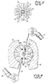
- Formation of armature coils requires simultaneous winding of two wires in two pairs of slots which are symmetrically opposite one another as shown in accompanying FIG. 2.
- coil 20 is wound in slot pair 22, 23 symmetrically opposite to coil 21 which is simultaneously wound in slot pair 24, 25.
- the typical flyer type winder includes two opposite flyers 30, 31 which can rotate around respective axes 32, 33 so that each of them dispenses an associated wire 34, 35 coming from a wire spool 36, 37 into a respective pair of coil receiving slots 38, 39 and 40, 41 aligned with prepositioned winding forms 42, 43.
- the winding forms are required to guide each wire into the coil receiving slots as the wire leaves the associated flyer.
- the two flyers 30 and 31 rotate at the same time so that each of them forms a coil in respective pairs of slots which are symmetrically disposed on opposite sides of a central transverse axis 80 of the armature.
- Flyers 30 and 31 are driven by independent motors 44, 45, which are controlled to rotate in unison so that both flyers reach, as precisely as possible, similar predetermined angular positions in time. In particular, the two flyers start and terminate rotation at the same time so that both coils are wound simultaneously with the same number of turns.
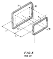
- FIG. 5 The wires relating to a few coil turns for respective opposite coils 20, 21 are shown.
- the turns of coil 21 are wound with higher tension, which subjects the wire to a greater amount of elongation for the same number of turns. This causes coil 21 to have less wire mass and to be more compact toward the central longitudinal axis 82 of the armature than coil 20.
- the formation of the overall coils of the armature requires a progressive build-up of wire turns and also of different coils. Later-wound turns and coils surmount earlier-wound turns and coils so that the later-wound material is farther away from central axis 82.
- one way in which to balance an armature involves measuring the amount of wire leaving each of the two wire spools during winding using encoders to determine the velocity or length of the wire. This measurement reveals approximately how much wire is being wound onto the armature by each of the two flyers. If it is determined that more wire is being wound onto the armature by one of the flyers than the other, than the rate at which wire is delivered to each of the flyers can be adjusted.
- the wire that is fed to the flyers is tensioned using wire tensioners such as hysteresis brakes.
- the brakes are adjusted to balance the amount of wire that is being fed to each of the flyers by varying the tension each brake applies to the wire. For example, the retarding force on the wire being wound onto one coil could be increased, so that subsequently, less wire is wound onto that coil.
- rotating encoders 60 for measuring wire consumption are typically placed immediately adjacent to the spool 36, as shown in FIG. 6, which is a reproduction of FIG. 6 of the above-mentioned application Serial No. 08/042,607.
- tensioning device 46 is typically placed downstream of encoder 60. After tensioning device 46, wire 34 runs over a pulley wheel 68 of a spring biased dancer arm 69 prior to reaching flyer 30.
- the dancer arm 69 is primarily required during operations in which the flyer undergoes abrupt changes in rotation direction and speed. In these situations the dancer arm accommodates any abrupt tightening or loosening of the wire that may occur by resiliently pivoting about axle 70 in the appropriate direction 71. Although the arrangement shown in FIG. 6 is satisfactory for balancing armatures in many situations, such an arrangement does not account for the changes in the length of the wire between tensioning device 46 and flyer 30 due to motions of the dancer arm 69 that might occur under extreme tensioning conditions. As a result, at any given time, the wire consumption measured by encoder 60 may not represent the amount of wire that has actually been wound onto the armature as accurately as might be desired.
- FIG. 7 is a reproduction of FIG. 11 of the above-mentioned application Serial No. 08/042,607.
- wire tension sensors 120 and 121 are provided to measure the tension of the wire being wound onto the armature by flyers 30 and 31.
- FIG. 7 can be used to balance armatures by maintaining the wire tensions measured by sensors 120 and 121 at the same level, tension sensors may not always be as precise as desired when operating at extremely high speeds.
- One of the components of conventional winding machines is the wire tensioner.
- two hysteresis brakes are used to tension the wires as they are fed to respective flyers.
- Conventional hysteresis brakes contain a stationary stator.
- a rotor is mounted within the stator for rotational motion.
- Current is supplied to the field coils of the stator to produce a retarding torque between the stator and the rotating rotor.
- a pulley attached to the rotor axis applies this retarding torque to the wire.
- the magnitude of the retarding torque is controlled by varying the current to the stator.
- the winding machine uses wire sensors adjacent to the flyers to determine the respective lengths of wire that are wound onto the armature by each of the two flyers during a predetermined period of time. Based on the relative lengths of the two wires wound onto the armature, the tensions applied by wire tensioning units are adjusted to equalize the lengths of the wires wound onto the armature during subsequent time periods. In most circumstances the mass of each wire length is essentially proportional to the wire's length, so that equalizing the lengths equalizes the masses, thereby balancing the armature.
- the predetermined period of time is the amount of time necessary to wind a pair of coils.
- Another embodiment of the winding machine of the present invention involves the use of multiple wire and position sensors to even more accurately determine the relative masses of the wires wound onto the armature.
- One pair of wire sensors is provided adjacent to the flyers and another pair is provided adjacent to the wire supplies. These sensors are used to determine the rate at which wire is being fed towards the flyers at these locations as a function of time.
- a third pair of sensors is connected to the pivoting axes of the dancer arms, to allow the determination of the rate of change of the lengths of wire supported by the respective dancer arms as a function of time.
- Optional wire thickness monitors are used to measure the diameters of the wires as they exit the wire supplies.
- a wire winding machine control system preferably microprocessor based -- is used to process the signals from the various sensors to determine the respective masses of the two wire lengths that are wound onto the armature during a predetermined period of time. By comparing the relative masses, the wire tension applied to each of the wires can be adjusted to equalized these masses during subsequent winding operations.
- An improved hysteresis brake unit uses a rotatable stator, rather than the conventional stationary stator design. Because the stator is rotatable relative to the housing and the rotor, after the torque control current supplied to the stator has been reduced, a motor can be used to rotate the stator relative to the rotor by a predetermined amount, thereby overcoming the effects of cogging.
- FIG. 1 is a perspective view of a conventional armature which can be wound in accordance with this invention.
- FIG. 2 is a simplified axial end view of the armature of FIG. 1 showing the dispositions of the core slots and the related coils.
- FIG. 3 is a simplified elevational view of a conventional two flyer winding machine.
- FIG. 4 is an enlarged view, partly in section, of the central portion of FIG. 3.
- FIG. 5 is a simplified perspective view, with certain features somewhat exaggerated, showing coil turns relating to opposite receiving slots of the armature which may be produced simultaneously by conventional armature winding apparatus.
- FIG. 6 is a simplified perspective view of an illustrative armature winding apparatus as shown in FIG. 6 of United States patent application serial No. 08/042,607.
- FIG. 7 is a simplified axial view of an illustrative armature winding apparatus as shown in FIG. 11 of United States patent application Serial No. 08/042,607.
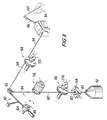
- FIG. 8 is a simplified perspective view of one side of an illustrative armature winding apparatus constructed in accordance with the present invention.
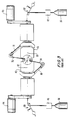
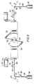
- FIG. 9 is a simplified axial view of both sides of the illustrative armature winding apparatus of FIG. 8.
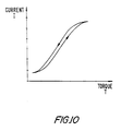
- FIG. 10 is a typical current-torque relationship for a hysteresis brake.
- FIG. 11 is a simplified perspective view of one side of a further illustrative armature winding apparatus constructed in accordance with the present invention.
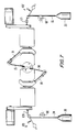
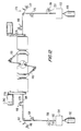
- FIG. 12 is a simplified axial view of both sides of the illustrative armature winding apparatus of FIG. 11.
- FIG. 13 is a schematic block diagram of an illustrative control system constructed in accordance with the present invention.
- FIG. 14 is a simplified sectional side view of a hysteresis brake unit constructed in accordance with the present invention.
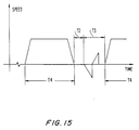
- FIG. 15 is an illustrative timing diagram of the speed of rotation of a winding machine flyer versus time.
- FIGS. 8 and 9 Equipment used with a first embodiment of the invention for a two flyer armature winding machine is shown in FIGS. 8 and 9.
- the equipment shown in FIG. 8 is that required for the flyer 100, which is also shown on the left side of FIG. 9. Similar equipment is provided for flyer 102 on the right side of FIG. 9.
- wires 104 and 106 are supplied to flyers 100 and 102 from left and right spools 108 and 110, respectively. From spool 108, the wire leads to a wire tensioner 112.
- Wire tensioner 112 includes a pulley wheel 114 about which wire 104 is preferably wound for more than 360°.
- Pulley wheel 114 has a central shaft mounted on supports of the machine frame (not shown) for rotation about axis 116.
- the central shaft of pulley wheel 114 is rigidly connected to the input shaft of a hysteresis brake 118, which is capable of supplying variable drag torque on pulley wheel 114 when the pulley wheel is turned in direction 119 to supply wire to flyer 100.
- the drag torque provided by brake 118 can be varied by adjusting the electric current that is applied to the coils of the brake.
- FIG. 10 shows a typical performance curve for the hysteresis brake where current I is plotted against braking torque T. Brakes of this type are commercially available from Magtrol, Inc. of Buffalo, N.Y. Alternatively, wire tensioners of the type shown in commonly assigned U.S. Patent 5,310,124 (incorporated by reference herein) can be employed if desired. As shown at the right side of FIG. 9, wire 106 passes through a wire tensioner 122, similar to that of wire tensioner 112.
- wires 104 and 106 run over pulley wheels 124 and 126 of spring biased dancer arms 128 and 130, respectively, prior to reaching flyers 100 and 102.
- the wire tensioners 112 and 122 are used to ensure that wires 104 and 106 have sufficient tension to guarantee that the coils wound onto armature 132 are sufficiently compact.
- the wire tensioners also maintain control of the wires as they are drawn from the spools by rotation of the flyers.
- the dancer arms are used to dampen the wire tension transients that accompany certain flyer operations, such as the operations required to connect wire leads to the commutator of armature 132. During these operations the flyers undergo abrupt changes in rotational direction and speed.
- the dancer arms pivot to accommodate any sudden tightening or loosening of the wire.
- dancer arm 128 pivots about axle 134, shown in FIG. 8.
- wires 104 and 106 pass through pulley wheels 136 and 138 of wire sensors 140 and 142, respectively.
- Wire sensors 140 and 142 are used to monitor the amount of wire that is wound onto the armature by flyers 100 and 102. Using a suitable control system, the amount of wire that is wound onto the armature by the respective flyers can be equalized to balance the armature.
- pulley wheel 136 is mounted to rotate about axis 144 by mounting its central shaft to the winding machine frame (not shown).
- the central shaft of pulley 136 is linked by means of a mechanical joint to the rotatable input of a suitable transducer, such as an encoder 146.
- Encoder 146 can supply output signals representing the rotations of pulley 136 about axis 144.
- encoder 146 may produce an output pulse each time pulley 136 rotates by a predetermined amount.
- Wire 104 is preferably looped for more than 360° around pulley wheel 136 and a pressure wheel (not shown) may press on the wire to ensure that it does not slip as it runs on the pulley wheel.
- Wire sensor 140 is preferably located along the associated wire 104 downstream from the wire tensioner 112 and the dancer arm 128.
- Wire sensor 142 is preferably of similar construction to that of wire sensor 140.
- Wire sensors 140 and 142 measure the amount of wire that has been wound onto the coils of armature 132.
- the amount of wire that has been wound onto the armature can be determined by using wire sensors 140 and 142 to measure rates of travel of the wires toward their respective flyers, or by measuring the length of wire consumed since some predetermined starting time, such as the beginning of winding of the pair of coils currently being wound.
- the wire sensors are used to determine the lengths of the wires that are wound onto each respective coil in a pair of coils.
- the lengths of the wires wound onto the coils are compared to determine to what degree the wire tensioners 112 and 122 should be adjusted. For example, if it is determined that the second coil has a longer length of wire wound onto it than the first coil, then the tension applied to the wire leading to the second coil can be increased by increasing the retarding force applied to the wire with wire tensioner 122. When the next pair of coils is wound, the higher tension for the second coil will cause less wire to be wound onto the second coil than was previously wound, thereby tending to balance the armature.
- the tension applied by wire tensioner 122 can be adjusted as appropriate, while the tension applied by wire tensioner 112 remains at a nominal value selected prior to winding.
- This type of arrangement is sometimes referred to as a "master-slave" configuration, where wire tensioner 112 acts as the master and wire tensioner 122 acts as the slave.
- wire tensioner 122 could be the master and wire tensioner 112 the slave, if desired. It is also possible to simultaneously adjust the tension applied by both wire tensioners 112 and 122.
- any suitable algorithm for adjusting the tensions applied by these devices can be employed.
- the tension applied by one of the wire tensioners (the slave) can be increased or decreased in a linear fashion, based on the measured difference in wound coil lengths, as shown in Equation 1.
- New.Tension Old. Tension + c * (X L - X R )
- New.Tension is the tension to be applied by the slave wire tensioner when the next pair of coils is wound.
- Old.Tension is the tension that was previously applied.
- X L and X R are the values of wire length measured by the wire sensors 140 and 142, respectively. The constant c is determined empirically.
- Equation 1 is one suitable expression for determining the tension to be applied by the slave wire tensioner. It is also possible to use an expression that has a quadratic, cubic, or higher order dependency on the measured difference in wire lengths. A set of two expressions similar to Equation 1 (or its quadratic or higher order variants) can also be used if the tensions applied by both wire tensioners 112 and 122 are to be adjusted.
- the algorithm used to adjust the wire tensioners can be implemented by the control system of the winding machine using an equation such as Equation 1 stored either as a set of instructions to be executed by, e.g., a microprocessor, or as a look-up table stored in a suitable memory device.
- Equation 1 stored either as a set of instructions to be executed by, e.g., a microprocessor, or as a look-up table stored in a suitable memory device.
- the purpose of making the periodic adjustments to the wire tensioners 112 and 122 is to is to reduce and ultimately substantially eliminate the difference between the lengths of the wires that are wound onto the armature to form the coils. This also typically has the effect of at least eventually reducing tension differences between the two wires. Equalizing the lengths (and therefore tensions) of the two wires wound onto the armature reduces differences which would exist in the two coil masses being wound, and also produces a similar compactness in the two coils. As has been described above, this balances opposing coils and thus the entire armature.
- the winding machine arrangement shown in FIGS. 8 and 9 and described above is superior to previously-known winding machines because the wire sensors 140 and 142 are placed directly adjacent to the flyers, with no intervening tensioning equipment.
- the measured wire length more accurately reflects the mass of the wire that has been wound onto the armature, because when dancer arms 128 and 130 pivot a different amount of wire may be wound onto the armature than would be detected by measuring the wire consumption in the vicinity of the spool. Because wire sensors 140 and 142 are directly adjacent to the flyers 100 and 102, the actual length of wire wound onto the armature is measured.
- FIGS. 11 and 12 further wire sensors can be provided to allow both the amount of wire wound onto the armature and the linear mass of the wound wire to be determined.
- two similar sets of equipment are used, one for each of the flyers 148 and 150.
- the equipment in FIG. 11 is used for flyer 148.
- Spool 152 supplies wire, whose diameter can be measured using an optional wire thickness gauge 154.
- Wire thickness gauges are well known.
- a typical gauge contains a source of illumination, such as a laser, which produces a beam of light perpendicular to the wire. The wire passing through the gauge intersects the beam allowing the diameter of the wire to be determined.
- a wire sensor 156 measures the amount of wire that is supplied from the spool.
- Wire sensor 156 operates similarly to wire sensor 140 (FIG. 8).
- Wire sensor 156 is used to periodically measure the rate of travel of the wire toward the flyer. After wire sensor 156, the wire passes though wire tensioner 158, which can be constructed similarly to that of wire tensioner 112 (FIG. 8).
- the wire passes through pulley wheel 160 of dancer arm 162, which is of the same type as dancer arm 128 (FIG. 8).
- Dancer arm 162 pivots about the axis of shaft 164 to accommodate abrupt changes in the tension of the wire.
- a position sensor having an encoder 166 can be used to determine the rotational position of dancer arm 128.
- the wire passes to flyer 148 via wire sensor 168, which is preferably constructed similarly to wire sensor 156.
- the winding machine parts shown on the right side of FIG. 12 --spool 170, wire gauge 172, wire sensor 174, wire tensioner 176, encoder 177, dancer arm 178, and wire sensor 180 -- are used with flyer 150.
- wire sensor 156 and encoder 166 allow the mass of the wires wound onto the armature to be accurately determined, even if extreme wire tensions and large movements of the dancer arms 162 and 178 are encountered.
- the mass of any segment of wire wound onto the coil is equal to the linear mass (mass per unit length) of the wire integrated over the length of the wire segment. Because the wire elongates under tension, the linear mass of wire that has been tensioned is less than the wire emerging from the spool.
- wire segment 182 which extends from spool 152 to wire tensioner 158, is relatively untensioned. Between the wire tensioner 158 and the armature 186, wire segment 184 is tensioned by the actions wire tensioner 158, dancer arm 162 and flyer 148.
- G1 is the linear mass of wire segment 182
- G2 is the linear mass of wire segment 184
- V1 and V2 are the velocities of the wire at the wire sensors 156 and 168, respectively.
- the variable VD is the rate of change in the length of the portion of wire segment 184 that is between wire tensioner 158 and wire sensor 168 (i.e. the change in the length of the wire supported by the dancer arm 16 per unit time).
- Equation 3 The total mass of a wire segment that is wound onto the armature, M, is given by Equation 3, where T is the period of time taken to wind the wire segment onto the armature.
- T is the period of time taken to wind the wire segment onto the armature.
- G1, V1, V2, and VD are known, so that the value of G2 can be obtained from Equation 2.
- the total mass of the wire segment wound onto the armature can then be obtained from Equation 3.
- the wire tensioners 158 and 176 can be adjusted appropriately to balance the armature.
- G1, V1, V1, and VD can be determined using the various sensors shown in FIG. 11. As the flyer draws wire from spool 152, the linear mass of wire segment 184 may vary slowly due to variations in the diameter of the wire. These variations can be sensed by the wire thickness gauge 154 to determine the value of G1 as a function of time. Alternatively, because the nominal wire diameter does not vary substantially, G1 can be assumed to be a constant.
- V1 can be obtained from the wire sensor 156.
- V2 can be obtained from the wire sensor 168.
- the rate of change in the length of the wire segment supported by the dancer arm, VD can be determined based on the known length of that wire segment as a function of the position of dancer arm 162 and the measured value of that position, which is provided by encoder 166.
- flyer 148 The equipment shown in FIG. 11 and on the left of FIG. 12 is used with flyer 148 to wind the wire onto the armature and to determine the total mass of any given segment of wire that is wound.
- the components on the right side of FIG. 12 are used to perform the same functions with flyer 150.
- flyer 150 By periodically comparing the total masses of the respective wire segments that have been wound onto the armature, the wire tensioners can be periodically adjusted to equalize the masses delivered to opposing armature coils, thereby balancing the armature.
- any suitable algorithm can be used to adjust the wire tensions provided by wire tensioners 158 and 176.
- a linear algorithm such as that defined by Equation 1, or a quadratic or higher order algorithm can be used.
- the coefficients for the various terms in the algorithm can be determined empirically for various wire and armature types.
- One suitable algorithm for determining to what extent the wire tensioners 158 and 176 should be adjusted is given by Equations 4 and 5.
- TR T0 + k * (MR - ML) / (MR + ML)
- TL T0 - k * (MR - ML) / (MR + ML)
- MR and ML are the respective masses of two opposing wire segments that have been wound onto the armature.
- the measurements necessary to determine MR and ML are made using the sensors shown on the right and left of FIG. 12, respectively.
- the winding machine control system determines MR and ML based on these measurements using Equation 3.
- TR and TL are the tensions to be applied by wire tensioners 158 and 176 in response to the values obtained for MR and ML.
- T0 is the nominal tension value, one which has been shown to generally produce satisfactory results.
- the constant k can be determined empirically for various combinations of wire type and armatures.
- a suitable winding machine arrangement such as the machine shown in FIGS. 8 and 9 can also use a torque adjustment algorithm based on Equations 4 and 5, if desired.
- sensors 140 and 142 can be used to monitor the wire lengths that are wound onto successive coils. After winding each pair of coils, the measured lengths can be compared. The respective tensions to be applied to the wires when winding the next set of coils can then be adjusted with wire tensioners 112 and 122 using Equations 4 and 5.
- Any suitable control system may be used to perform the processing necessary to determine the masses of respective wire segments from the sensor readings and to control the operation of the winding machine.
- dedicated circuitry could be used.
- Another suitable control system design is based on a microprocessor. An illustrative microprocessor-based control system is shown in FIG. 13.
- Control system 188 uses microprocessor 190 to execute instructions loaded into memory 192. By executing the appropriate instructions, microprocessor 190 processes the signals from the various winding machine sensors and implements the control routines necessary to balance the armature during winding.
- wire sensors used to measure the amount of wire being wound onto the armature are of the type that produce a certain number of digital pulses per revolution of a pulley wheel, these pulses must be processed.
- One suitable approach for processing these sensor signals is to count the signals from the wire sensor encoders per unit time, thereby allowing the control system 188 to determine the necessary wire velocities.
- the pulses from encoders 194, 196, 198, 200, 202, and 204 can be counted by counters 206, 208, 210, 212, 214, and 216, respectively. If a sensor arrangement such as that shown in FIGS. 11 and 12 is used, six counters can be used to count the various signal pulses from the six encoders 218, 166, 220, 222, 177, and 224. Data from the counters is provided to the microprocessor 190 via bus 226. The microprocessor 190 can process the counter data to determine the velocities V1, V2, and VD.
- two counters can be used to count the signal pulses from encoders 140 and 142.
- the microprocessor 190 can then process the counter data to determine the length of wire that has been drawn past each wire sensor.
- the output of the wire gauges 154 and 172 can be provided to microprocessor 190 via a suitable interface device 228.
- Interface device 228 can be, for example, a multi-channel analog-to-digital converter that receives the outputs from wire gauges 154 and 172 at inputs 230 and 232, respectively.
- interface device 228 can be a digital interface capable of receiving digital signals from the wire gauges that are indicative of the measured wire thicknesses.
- flyer drive 234 (FIG. 9) can provide a position signal at output 236 or flyer drive 238 can provide a position signal at output 240.
- the position signal from the flyer drive which is indicative of flyer rotation or angular position, can be provided to microprocessor 190 via a suitable interface device 242.
- the control system 188 processes the signals from the various sensors and determines the magnitude of any adjustments to be made to the tensions that are applied by the wire tensioners using any suitable algorithm, as described above.
- The-control system 188 generates corresponding digital control signals, which are provided to digital-to-analog converters 244 and 246.
- Digital-to-analog converters 244 and 246 convert the digital control output signals to the analog form typically required by wire tensioners such as hysteresis brakes 248 and 250, to modify the torque they apply and thereby adjust the tension of the wires. Prior to being supplied to the brakes, these signals can be amplified by amplifiers 252 and 254.
- Line 256 can be used for entering ideal wire tensions, e.g., using potentiometers to supply analog signals that are transformed to digital signals for microprocessor 190.
- Lines 258 can make up a serial link coming from a host or remote controller which can be the winder's ultimate controller, so that when setting the winder for a particular type of armature, the ideal tension is automatically transferred to microprocessor 190 without requiring any further local input.
- Keyboard and monitor 260 are alternative input devices which an operator can use to supply the required tension conditions.
- any suitable sensor arrangement for sensing the amount of wire consumed or the position of the dancer arm can be used.
- sensors can be provided that contain counters and processing circuitry. If the sensors contain such additional circuitry, the signals transmitted from the sensors to the control system 188 are more directly indicative of the parameter being measured.
- a wire sensor output might be an analog or digital signal having a value equal to the length of wire consumed or the velocity of the wire.
- a position sensor for determining the position of the dancer arm could provide an analog or digital output signal that indicates the position and velocity of the dancer arm.
- the counters in FIG. 13 are shown connected to microprocessor 190 via bus 226, the analog or digital output signals from the various sensors could alternatively be supplied to microprocessor 190 via suitable interface circuitry 262.
- wire gauge sensors the flyer drivers, the circuitry for entering the wire tension, the host, and the keyboard and monitor are shown connected directly to the microprocessor 190, the outputs of some or all of these can be provided to microprocessor 190 via suitable interface circuitry 264 connected to bus 226, if desired.
- Another aspect of the present invention relates to improvements to the wire tensioning arrangement used to tension the wire as it is wound onto a wound electric motor component (e.g., a rotor or stator) for a dynamo-electric machine.
- a wound electric motor component e.g., a rotor or stator
- one suitable type of wire tensioner is based on a hysteresis brake.
- hysteresis brakes have an axle connected to a rotor that rotates within a stationary stator. By varying the current supplied to the field coils of the stator, a variable torque is applied to the axle.
- the hysteresis brakes used with the wire winding machines described above have pulley wheels about which wire to be tensioned is wound. As the flyer draws wire past the hysteresis brake, the pulley wheel rotates. When a current is supplied to the field coils of the stator, a retarding torque is generated by the brake. The torque applied by the brake is a function of the current supplied to the brake, generally following the relationship shown in FIG. 10.
- a wire tensioner 266 is provided having a hysteresis clutch 268, as shown in FIG. 14.
- hysteresis clutch 268 is a clutch such as a clutch in the HCS series of clutch models available from Magtrol Inc. of Buffalo, New York.
- Hysteresis clutch 268 has a rotor 270 that is connected to an axle 272, which is rotatably mounted in stationary housing 274.
- a pulley 276 or similar member for engaging wire 278 is connected to axle 272.
- Clutch 268 receives a controlling current via input 282.
- Rotating stator 280 is rotated relative to the stationary housing 274 by motor 284 using axle 281.
- the actual speed of rotation of the rotating stator 280 is preferably reduced from the speed of rotation of the motor 284 by reduction gear 283.
- motor 284 is a fixed speed AC motor that receives a drive voltage via input 290.
- Pulley 276 typically rotates so as to feed wire toward the electric motor component to be wound.
- Rotating stator 280 rotates in the opposite direction.
- the hysteresis clutch 268 provides a retarding torque to the pulley wheel 276.
- the magnitude of the retarding torque is primarily determined by the value of the current applied to the hysteresis clutch 268 via input 282. By varying the current supplied to input 282, the wire 278 can be tensioned as desired.
- the speed of rotation of a typical winding machine flyer during the process of winding an armature is shown in FIG. 15.
- the flyer winds wire onto a first armature coil.
- the flyer is stationary while the winding machine moves the appropriate lead connection point into position.
- the torque applied to the wire during the process of forming lead connections be relatively low. Accordingly, during period T2, the current supplied to the wire tensioner 266 via input 282 is reduced.
- the rotation of motor 284 causes the rotating stator 280 to rotate relative to rotor 270, which eliminates the effects of cogging.
- the torque applied by the wire tensioner 266 during period T2 therefore quickly drops to a relatively low level.
- the winding machine performs various lead connection operations. (As shown in FIG. 15, during time period T3 the direction of rotation of the flyer may reverse.) Because the torque applied by wire tensioner 266 was lowered during period T2, the lead connections during period T3 can be formed without deforming the lead connections (e.g., without bending the tangs of a commutator).
- An advantage of this approach is that rotation of the rotating stator 280 by motor 284 can be accomplished during period T2 prior to the lead connection step. No additional time is required to complete the winding cycle.
- hysteresis clutch 268 in wire tensioner 266 a significant advantage of using hysteresis clutch 268 in wire tensioner 266 is that the motor 284 can be used to rotate the rotating stator 280 relative to the rotor 270 to overcome the effects of cogging.
- Another significant advantage of using hysteresis clutch 268 in wire tensioner 266 is that the direction of rotation of the pulley wheel 276 can be reversed to pick up slack that may develop at certain stages in the winding process.
- the pulley wheel is rotated in a forward direction by the force of the wire being drawn past it towards the electric motor part being wound (e.g, the armature or stator), while the motor 284 rotates the rotating stator in the opposite direction.
- the direction of the pulley wheel may reverse, in order to pick up slack that has developed in the wire and to maintain an appropriate tension on the wire.
- the motion of the flyer may create slack in the wire between the pulley wheel and the armature.
- the retarding torque applied to the pulley wheel 276 by the hysteresis clutch 268 causes the pulley wheel to reverse its direction of rotation, while the motor 284 continues to rotate the rotating stator 280, so that instead of allowing slack to develope in the wire, the pulley wheel draws wire back from the armature.
- the torque applied to the pulley wheel 276 by hysteresis clutch 268 can be increased or decreased by increasing or decreasing the current applied to the clutch 268, if desired.
- dancer arms are provided upstream from the pulley wheel to recover any wire that is drawn back from the direction of the wound motor component.
- Robotic wire manipulation devices are typically used to position the ends of the coil leads as they are connected to terminals on stators or anchoring points on workpiece holders. These robotic manipulators position wires in a way that makes it desirable to be able to draw wire back towards the pulley wheel.
- the retarding torque applied to the pulley wheel 276 causes the direction of rotation of the pulley wheel to reverse whenever wire slack develops, while motor 284 continues to rotate the rotating stator 280.
- the hysteresis clutch 268 is preferably controlled by control system 188 (FIG. 13).
- Microprocessor 190 executes instructions stored in memory 192 that direct the microprocessor to generate appropriate digital motor control signals, which are provided to digital-to-analog converter 286.
- the analog output of digital-to-analog converter 286 can be amplified by an amplifier 288, if desired.
- the output of amplifier 288 is preferably an analog control signal that can be used to control the torque applied to pulley wheel 276 by hysteresis clutch 268, by supplying a suitable input control current at input 282, as shown in FIG. 14.
- a similar digital-to-analog converter and amplifier may be provided to generate the control voltage applied to input 290 of motor 284 (FIG. 14).
Landscapes
- Engineering & Computer Science (AREA)
- Manufacturing & Machinery (AREA)
- Power Engineering (AREA)
- Manufacture Of Motors, Generators (AREA)
- Coil Winding Methods And Apparatuses (AREA)
- Tension Adjustment In Filamentary Materials (AREA)
Applications Claiming Priority (2)
| Application Number | Priority Date | Filing Date | Title |
|---|---|---|---|
| US08/311,637 US5628472A (en) | 1993-04-02 | 1994-09-23 | Methods and apparatus for balancing armatures during coil winding |
| US311637 | 1994-09-23 |
Publications (2)
| Publication Number | Publication Date |
|---|---|
| EP0703658A1 true EP0703658A1 (de) | 1996-03-27 |
| EP0703658B1 EP0703658B1 (de) | 2001-01-03 |
Family
ID=23207795
Family Applications (1)
| Application Number | Title | Priority Date | Filing Date |
|---|---|---|---|
| EP95114813A Expired - Lifetime EP0703658B1 (de) | 1994-09-23 | 1995-09-20 | Verfahren und Vorrichtung zum Ausbalanzieren von Rotorwicklungen während des Wicklungsvorganges |
Country Status (4)
| Country | Link |
|---|---|
| US (2) | US5628472A (de) |
| EP (1) | EP0703658B1 (de) |
| CA (1) | CA2156352A1 (de) |
| DE (1) | DE69519780T2 (de) |
Cited By (6)
| Publication number | Priority date | Publication date | Assignee | Title |
|---|---|---|---|---|
| EP0810718A1 (de) * | 1996-05-30 | 1997-12-03 | AXIS S.p.A. | Drahttensor einer Maschine zum Wickeln der Spule einer dynamoelektrischen Maschine |
| WO1999012249A1 (en) * | 1997-08-29 | 1999-03-11 | General Electric Company | Systems, methods and apparatus for winding conductive wires for a stator of an electric motor |
| US6036135A (en) * | 1997-05-16 | 2000-03-14 | Ats Automation Tooling System Inc. | Winding of coils into axial slots in rotationally symmetric bodies of electrical devices |
| US6145772A (en) * | 1998-01-21 | 2000-11-14 | Ats Automation Tooling Systems Inc. | Device for winding coils in axial grooves of rotationally symmetrical bodies of electric equipment |
| DE19851272B4 (de) * | 1997-11-25 | 2008-03-06 | Asmo Co., Ltd., Kosai | Elektromotor und Verfahren zu dessen Herstellung |
| ITPI20120010A1 (it) * | 2012-01-24 | 2013-07-25 | Atop Spa | Apparecchiatura e metodo per avvolgere e terminare nuclei per macchine dinamo elettriche |
Families Citing this family (8)
| Publication number | Priority date | Publication date | Assignee | Title |
|---|---|---|---|---|
| JP3708288B2 (ja) * | 1997-05-23 | 2005-10-19 | 松下電器産業株式会社 | 電機子コイルの巻線機とその巻線機による巻線方法 |
| DE10029885A1 (de) * | 2000-06-16 | 2001-12-20 | Zahnradfabrik Friedrichshafen | Fernbedienbare Hysteresebremse |
| JP4435739B2 (ja) * | 2004-01-28 | 2010-03-24 | 三菱電機株式会社 | 回転電機の巻線組立の製造方法およびその巻線組立の製造装置 |
| GB0517659D0 (en) * | 2005-08-31 | 2005-10-05 | Watkins Penelope A | Tensile tester |
| KR100775986B1 (ko) | 2006-10-19 | 2007-11-15 | 한국전기연구원 | 초전도 선재 권선장치 및 권선방법 |
| JP4285559B2 (ja) * | 2007-04-26 | 2009-06-24 | 株式会社デンソー | 回転子の巻線装置及び回転子の製造方法 |
| KR101721326B1 (ko) * | 2015-08-11 | 2017-03-29 | 두산중공업 주식회사 | 초전도 선재의 가이드 장치 |
| JP6589933B2 (ja) * | 2017-05-12 | 2019-10-16 | 株式会社村田製作所 | 巻線装置 |
Citations (4)
| Publication number | Priority date | Publication date | Assignee | Title |
|---|---|---|---|---|
| US4260793A (en) | 1979-04-02 | 1981-04-07 | The Upjohn Company | 9-Deoxy-9-methylene-inter-phenylene-19-oxo-PGF1 compounds |
| US4381852A (en) * | 1980-10-20 | 1983-05-03 | Westinghouse Electric Corp. | Automatic tensioning control for winding stator coils |
| EP0536981A2 (de) * | 1991-10-07 | 1993-04-14 | Globe Products Inc. | Verfahren und Vorrichtung für die Überwachung und Steuerung einer Ankerwickelmaschine mit einer Detektion vermisster Haken |
| US5310124A (en) | 1992-04-29 | 1994-05-10 | Axis Usa, Inc. | Wire tensioner with program controlled bidirectional pulley wheel |
Family Cites Families (9)
| Publication number | Priority date | Publication date | Assignee | Title |
|---|---|---|---|---|
| US4062502A (en) * | 1976-10-21 | 1977-12-13 | The Globe Tool And Engineering Company | Wire tension control apparatus especially for coil winding machines |
| JPS62196050A (ja) * | 1986-02-24 | 1987-08-29 | Toshiba Corp | コイル巻回装置 |
| US4880173A (en) * | 1987-06-09 | 1989-11-14 | Globe Products Inc. | Wire supply method and apparatus |
| JP2604029B2 (ja) * | 1989-02-17 | 1997-04-23 | 株式会社ミツバ | 巻線用張力発生装置 |
| JP2716786B2 (ja) * | 1989-03-22 | 1998-02-18 | 株式会社ミツバ | モータ回転子の巻線状態検出装置 |
| US5219124A (en) * | 1989-12-04 | 1993-06-15 | Industrial Technology Research Institute | Multi-phase synchronous automatic winding method and apparatus for motor stators |
| JPH0734630B2 (ja) * | 1990-11-08 | 1995-04-12 | アスモ株式会社 | 回転電機子の巻線方法 |
| US5413289A (en) * | 1991-07-30 | 1995-05-09 | Axis Usa, Inc. | Programmably controlled armature winding apparatus |
| US5383619A (en) * | 1993-04-02 | 1995-01-24 | Axis Usa, Inc. | Methods and apparatus for winding armatures with improved balance |
-
1994
- 1994-09-23 US US08/311,637 patent/US5628472A/en not_active Expired - Fee Related
-
1995
- 1995-08-16 CA CA002156352A patent/CA2156352A1/en not_active Abandoned
- 1995-09-20 EP EP95114813A patent/EP0703658B1/de not_active Expired - Lifetime
- 1995-09-20 DE DE69519780T patent/DE69519780T2/de not_active Expired - Fee Related
-
1996
- 1996-09-12 US US08/713,241 patent/US5664735A/en not_active Expired - Fee Related
Patent Citations (4)
| Publication number | Priority date | Publication date | Assignee | Title |
|---|---|---|---|---|
| US4260793A (en) | 1979-04-02 | 1981-04-07 | The Upjohn Company | 9-Deoxy-9-methylene-inter-phenylene-19-oxo-PGF1 compounds |
| US4381852A (en) * | 1980-10-20 | 1983-05-03 | Westinghouse Electric Corp. | Automatic tensioning control for winding stator coils |
| EP0536981A2 (de) * | 1991-10-07 | 1993-04-14 | Globe Products Inc. | Verfahren und Vorrichtung für die Überwachung und Steuerung einer Ankerwickelmaschine mit einer Detektion vermisster Haken |
| US5310124A (en) | 1992-04-29 | 1994-05-10 | Axis Usa, Inc. | Wire tensioner with program controlled bidirectional pulley wheel |
Non-Patent Citations (1)
| Title |
|---|
| PATENT ABSTRACTS OF JAPAN * |
Cited By (7)
| Publication number | Priority date | Publication date | Assignee | Title |
|---|---|---|---|---|
| EP0810718A1 (de) * | 1996-05-30 | 1997-12-03 | AXIS S.p.A. | Drahttensor einer Maschine zum Wickeln der Spule einer dynamoelektrischen Maschine |
| US5826774A (en) * | 1996-05-30 | 1998-10-27 | Axis Usa, Inc. | Wire tensioner for dynamo-electric machine coil winder |
| US6036135A (en) * | 1997-05-16 | 2000-03-14 | Ats Automation Tooling System Inc. | Winding of coils into axial slots in rotationally symmetric bodies of electrical devices |
| WO1999012249A1 (en) * | 1997-08-29 | 1999-03-11 | General Electric Company | Systems, methods and apparatus for winding conductive wires for a stator of an electric motor |
| DE19851272B4 (de) * | 1997-11-25 | 2008-03-06 | Asmo Co., Ltd., Kosai | Elektromotor und Verfahren zu dessen Herstellung |
| US6145772A (en) * | 1998-01-21 | 2000-11-14 | Ats Automation Tooling Systems Inc. | Device for winding coils in axial grooves of rotationally symmetrical bodies of electric equipment |
| ITPI20120010A1 (it) * | 2012-01-24 | 2013-07-25 | Atop Spa | Apparecchiatura e metodo per avvolgere e terminare nuclei per macchine dinamo elettriche |
Also Published As
| Publication number | Publication date |
|---|---|
| US5664735A (en) | 1997-09-09 |
| US5628472A (en) | 1997-05-13 |
| CA2156352A1 (en) | 1996-03-24 |
| DE69519780T2 (de) | 2001-08-02 |
| EP0703658B1 (de) | 2001-01-03 |
| DE69519780D1 (de) | 2001-02-08 |
Similar Documents
| Publication | Publication Date | Title |
|---|---|---|
| EP0703658B1 (de) | Verfahren und Vorrichtung zum Ausbalanzieren von Rotorwicklungen während des Wicklungsvorganges | |
| US5310124A (en) | Wire tensioner with program controlled bidirectional pulley wheel | |
| CN101486421B (zh) | 一种用来控制馈送纱线或丝线到机器的系统和相关方法 | |
| EP0078979B1 (de) | Spulvorrichtung | |
| JP2007519935A (ja) | 移動ウェブの弾性係数を決定する方法 | |
| EP0618661B1 (de) | Verfahren und Vorrichtungen zum Wickeln eines Ankers mit verbesserter Auswuchtung | |
| JPS61197356A (ja) | 張力制御装置 | |
| EP0233295B1 (de) | Zufuhrmechanismus eines drahtes bei schneiddrahtfunkerosionsvorrichtung | |
| CN106774142A (zh) | 绕线机电子凸轮控制系统及控制方法 | |
| KR20070116148A (ko) | 권취 시스템을 위해 설계된 크릴을 작동시키는 방법과 장치그리고 대응 크릴 | |
| KR100220295B1 (ko) | 논슬립형 직선 신선기 | |
| JP2002020038A (ja) | 糸の張力及び長さの制御装置 | |
| KR0132386B1 (ko) | 권선장력조절형권선기 | |
| JP2001328766A (ja) | 張力制御装置 | |
| JPH0442310B2 (de) | ||
| JP2921583B2 (ja) | 撚り線若しくはロープの製造方法及びその装置 | |
| JP3292687B2 (ja) | 張力制御装置 | |
| JP2008018466A (ja) | 伸線機における巻き出しトルク調整装置 | |
| JPH05278943A (ja) | 巻線のテンション制御装置 | |
| JP2805562B2 (ja) | プラントのモータ制御システム | |
| JPH11186085A (ja) | コイルの巻線方法および巻線装置 | |
| CN119683410A (zh) | 一种恒张力放线器 | |
| JP2863912B2 (ja) | Szスロットスペーサへの心線落とし込み方法 | |
| JPS5834125Y2 (ja) | 張力調整装置を有する巻き付け機 | |
| CN120413192A (zh) | 多芯线绞线绕包机 |
Legal Events
| Date | Code | Title | Description |
|---|---|---|---|
| PUAI | Public reference made under article 153(3) epc to a published international application that has entered the european phase |
Free format text: ORIGINAL CODE: 0009012 |
|
| AK | Designated contracting states |
Kind code of ref document: A1 Designated state(s): CH DE ES FR GB IT LI NL SE |
|
| 17P | Request for examination filed |
Effective date: 19960920 |
|
| 17Q | First examination report despatched |
Effective date: 19970120 |
|
| GRAG | Despatch of communication of intention to grant |
Free format text: ORIGINAL CODE: EPIDOS AGRA |
|
| GRAG | Despatch of communication of intention to grant |
Free format text: ORIGINAL CODE: EPIDOS AGRA |
|
| GRAH | Despatch of communication of intention to grant a patent |
Free format text: ORIGINAL CODE: EPIDOS IGRA |
|
| GRAH | Despatch of communication of intention to grant a patent |
Free format text: ORIGINAL CODE: EPIDOS IGRA |
|
| GRAA | (expected) grant |
Free format text: ORIGINAL CODE: 0009210 |
|
| AK | Designated contracting states |
Kind code of ref document: B1 Designated state(s): CH DE ES FR GB IT LI NL SE |
|
| PG25 | Lapsed in a contracting state [announced via postgrant information from national office to epo] |
Ref country code: SE Free format text: THE PATENT HAS BEEN ANNULLED BY A DECISION OF A NATIONAL AUTHORITY Effective date: 20010103 Ref country code: NL Free format text: LAPSE BECAUSE OF FAILURE TO SUBMIT A TRANSLATION OF THE DESCRIPTION OR TO PAY THE FEE WITHIN THE PRESCRIBED TIME-LIMIT Effective date: 20010103 Ref country code: ES Free format text: THE PATENT HAS BEEN ANNULLED BY A DECISION OF A NATIONAL AUTHORITY Effective date: 20010103 |
|
| REG | Reference to a national code |
Ref country code: CH Ref legal event code: EP |
|
| REF | Corresponds to: |
Ref document number: 69519780 Country of ref document: DE Date of ref document: 20010208 |
|
| ITF | It: translation for a ep patent filed | ||
| ET | Fr: translation filed | ||
| REG | Reference to a national code |
Ref country code: CH Ref legal event code: NV Representative=s name: HEPP, WENGER & RYFFEL AG |
|
| NLV1 | Nl: lapsed or annulled due to failure to fulfill the requirements of art. 29p and 29m of the patents act | ||
| PLBE | No opposition filed within time limit |
Free format text: ORIGINAL CODE: 0009261 |
|
| STAA | Information on the status of an ep patent application or granted ep patent |
Free format text: STATUS: NO OPPOSITION FILED WITHIN TIME LIMIT |
|
| REG | Reference to a national code |
Ref country code: GB Ref legal event code: IF02 |
|
| 26N | No opposition filed | ||
| PGFP | Annual fee paid to national office [announced via postgrant information from national office to epo] |
Ref country code: GB Payment date: 20020904 Year of fee payment: 8 |
|
| PG25 | Lapsed in a contracting state [announced via postgrant information from national office to epo] |
Ref country code: GB Free format text: LAPSE BECAUSE OF NON-PAYMENT OF DUE FEES Effective date: 20030920 |
|
| GBPC | Gb: european patent ceased through non-payment of renewal fee |
Effective date: 20030920 |
|
| PGFP | Annual fee paid to national office [announced via postgrant information from national office to epo] |
Ref country code: CH Payment date: 20080923 Year of fee payment: 14 |
|
| PGFP | Annual fee paid to national office [announced via postgrant information from national office to epo] |
Ref country code: FR Payment date: 20080917 Year of fee payment: 14 |
|
| PGFP | Annual fee paid to national office [announced via postgrant information from national office to epo] |
Ref country code: DE Payment date: 20081125 Year of fee payment: 14 |
|
| REG | Reference to a national code |
Ref country code: CH Ref legal event code: PL |
|
| REG | Reference to a national code |
Ref country code: FR Ref legal event code: ST Effective date: 20100531 |
|
| PG25 | Lapsed in a contracting state [announced via postgrant information from national office to epo] |
Ref country code: FR Free format text: LAPSE BECAUSE OF NON-PAYMENT OF DUE FEES Effective date: 20090930 Ref country code: DE Free format text: LAPSE BECAUSE OF NON-PAYMENT OF DUE FEES Effective date: 20100401 |
|
| PG25 | Lapsed in a contracting state [announced via postgrant information from national office to epo] |
Ref country code: LI Free format text: LAPSE BECAUSE OF NON-PAYMENT OF DUE FEES Effective date: 20090930 Ref country code: CH Free format text: LAPSE BECAUSE OF NON-PAYMENT OF DUE FEES Effective date: 20090930 |
|
| PG25 | Lapsed in a contracting state [announced via postgrant information from national office to epo] |
Ref country code: IT Free format text: LAPSE BECAUSE OF NON-PAYMENT OF DUE FEES Effective date: 20090920 |
|
| PGFP | Annual fee paid to national office [announced via postgrant information from national office to epo] |
Ref country code: IT Payment date: 20100907 Year of fee payment: 16 |
|
| PGRI | Patent reinstated in contracting state [announced from national office to epo] |
Ref country code: IT Effective date: 20110616 |
|
| PG25 | Lapsed in a contracting state [announced via postgrant information from national office to epo] |
Ref country code: IT Free format text: LAPSE BECAUSE OF NON-PAYMENT OF DUE FEES Effective date: 20110920 |