EP0703677B1 - Codeur perceptuel en sous-bandes - Google Patents
Codeur perceptuel en sous-bandes Download PDFInfo
- Publication number
- EP0703677B1 EP0703677B1 EP95306733A EP95306733A EP0703677B1 EP 0703677 B1 EP0703677 B1 EP 0703677B1 EP 95306733 A EP95306733 A EP 95306733A EP 95306733 A EP95306733 A EP 95306733A EP 0703677 B1 EP0703677 B1 EP 0703677B1
- Authority
- EP
- European Patent Office
- Prior art keywords
- bit
- signal
- frequency
- bits
- frequency subbands
- Prior art date
- Legal status (The legal status is an assumption and is not a legal conclusion. Google has not performed a legal analysis and makes no representation as to the accuracy of the status listed.)
- Expired - Lifetime
Links
- 230000005236 sound signal Effects 0.000 claims description 10
- 238000013139 quantization Methods 0.000 claims description 8
- 238000005070 sampling Methods 0.000 claims description 7
- 238000000034 method Methods 0.000 description 6
- 238000010586 diagram Methods 0.000 description 3
- 230000003247 decreasing effect Effects 0.000 description 2
- 238000004364 calculation method Methods 0.000 description 1
- 125000004122 cyclic group Chemical group 0.000 description 1
- 238000010606 normalization Methods 0.000 description 1
- 230000003252 repetitive effect Effects 0.000 description 1
Images


Classifications
-
- H—ELECTRICITY
- H04—ELECTRIC COMMUNICATION TECHNIQUE
- H04B—TRANSMISSION
- H04B1/00—Details of transmission systems, not covered by a single one of groups H04B3/00 - H04B13/00; Details of transmission systems not characterised by the medium used for transmission
- H04B1/66—Details of transmission systems, not covered by a single one of groups H04B3/00 - H04B13/00; Details of transmission systems not characterised by the medium used for transmission for reducing bandwidth of signals; for improving efficiency of transmission
- H04B1/665—Details of transmission systems, not covered by a single one of groups H04B3/00 - H04B13/00; Details of transmission systems not characterised by the medium used for transmission for reducing bandwidth of signals; for improving efficiency of transmission using psychoacoustic properties of the ear, e.g. masking effect
Definitions
- This invention relates to a frequency subband encoding apparatus, and more particularly to a frequency subband encoding apparatus wherein mask levels for individual frequency subbands are calculated from a digital audio signal based on a psychoacoustic model and signal levels of the individual frequency subbands are detected from samples of the individual frequency subbands, and then signal to mask level ratios which are ratios of the signal levels and the mask levels are calculated for the individual frequency subbands and bit allocation amounts for the individual frequency subbands are determined from the signal to mask level ratios, whereafter samples of the individual frequency subbands are quantized with quantization step numbers determined from the bit allocation amounts.
- a frequency subband encoding apparatus is described in the ISO/IEC 11172-3 standards (hereinafter referred to as "MPEG/Audio system"), Layer 1.
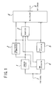
- FIG. 5 shows in block diagram the conventional frequency subband encoding apparatus.
- the frequency subband encoding apparatus includes a subband filter 1, a scale factor determinator 2, a quantizer 3, an SMR calculator 4 for outputting, for each of frequency subbands, a signal to mask level ratio (hereinafter referred to as SMR) which is a ratio between a signal level of the frequency subband and a mask level for the frequency subband based on a psychoacoustic model, a bit allocator 15 for determining a bit allocation amount, and a multiplexer 6.
- SMR signal to mask level ratio
- the subband filter 1 outputs values of a PCM (Pulse Code Modulation) signal 7 divided into 32 frequency subbands.
- the sampling frequency of the output signal of the PCM signal 7 is equal to 1/32 the sampling frequency of the PCM signal 7.
- the scale factor determinator 2 determines, from an output value of each of the frequency subbands of the subband filter 1, and outputs a scale factor for use to perform normalization for each 12 samples of the frequency subband.
- the SMR calculator 4 calculates a mask level for each of the individual frequency subbands from the PCM signal 7 based on a psychoacoustic model, calculates a signal level from samples of each of the frequency subbands and the corresponding scale factor, and calculates and outputs, for each frequency subband, a ratio (SMR) between the signal level and the mask level, which is a ratio between the two levels.
- the bit allocator 15 determines a bit allocation amount for each of the frequency subband from the SMR of the frequency subband.
- the quantizer 3 quantizes, with the bit allocation amount and the scale factor for each of the frequency subbands, samples of the frequency subband and outputs the thus quantized samples.
- the multiplexer 6 multiplexes the bit allocation information from the bit allocator 15, the scale factors from the scale factor determinator 2 and the quantized values from the quantizer 3 and outputs a bit stream 8.
- the number of bits included in one frame of the "MPEG/Audio Layer 1" system depends upon the values of the bit rate and the sampling frequency. As an example, when the bit rate is 192 kbps and the sampling frequency is 48 kHz, the number of bits of one frame is 1,536 bits in accordance with the standards mentioned above.
- the structure of one frame of the "MPEG/Audio Layer 1" system includes, for example, as shown in FIG. 6, factors of a header, a CRC (Cyclic Redundancy Code), a bit allocation, a scale factor, a sample and an ancillary bit.
- a CRC Cyclic Redundancy Code
- the header normally includes 32 bits, and the bit allocation requires 4 bits for each frequency subband and totally requires 128 (4 x 32) bits/ch. The other factors vary depending upon conditions.
- the header includes a bit representing whether or not a CRC is present. When a CRC is present, 16 bits are required for the CRC.
- the scale factor requires, when the bit allocation to each frequency subband is not equal to 0, 6 bits for each frequency subband.
- the sample requires, when the bit allocation to each frequency subband is not equal to 0, 12 bits for each one bit of the bit allocation.
- the ancillary bit includes bits provided by a number equal to the remaining number when a total number of bits mentioned above is subtracted from a total bit number of one frame.
- a maximum bit number allocated by bit allocation processing exhibits a maximum value when the ancillary bit is not allocated intentionally without a CRC.
- the total bit number of the scale factor and the sample which is an allocatable bit number of one frame in the aforementioned case wherein the bit rate is 192 kbps and the sampling frequency is 48 kHz is 1,376 (1,536 - (32 + 128)) bits.
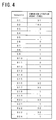
- the relationship between the allocated bit number for each of the frequency subbands and the signal to noise ratio (S/N ratio) which depends upon the allocated bit number is illustrated in FIG. 7.
- the bit numbers allocated to the frequency subband range from 0 to 15 bits except one bit (not shown in FIG. 7).
- FIG. 8 is a flow chart illustrating bit allocation processing of the conventional frequency subband encoding apparatus shown in FIG. 5. While the MPEG/Audio system allows encoding of up to 2 channels, description is given here of bit allocation processing for one channel.
- step P1 a frequency subband which exhibits a maximum SMR among SMR values of the 32 frequency subbands is detected, and the allocated bit number of the frequency subband is increased by one step (FIG. 7) and a new SMR is detected in accordance with the thus increased bit number.
- bits are allocated to the frequency subband at first (when 2 bits are allocated to the frequency subband to which 0 bit has been allocated in FIG.
- step P2 it is discriminated whether or not the allocatable bit number is equal to or greater than 30, and if the allocatable bit number is equal to or greater than 30, then the control sequence returns to step P1. On the contrary if the allocatable bit number is smaller than 30, the control sequence advances to step P3. At step P3, it is discriminated whether or not the allocatable bit number is smaller than 12. If the allocatable bit number is smaller than 12, then the processing is ended. However, if the allocatable bit number is equal to or greater than 12, then the control sequence advances to step P4. At step P4, frequency subbands to which bits have not been allocated are removed from the object of comparison processing of the SMR so that allocation processing may not occur later with the frequency subbands.
- step P5 a frequency subband which exhibits a maximum SMR among the SMR values of the 32 frequency subbands is detected, and the allocated bit number of the frequency subband is increased by one step.
- the allocated bit number becomes equal to 15 which is the limit value, then the frequency subband is removed from the object of comparison processing of the SMR so that allocation processing may not thereafter occur with the frequency subband. Further, the allocated bit number is subtracted from the allocatable bit number.
- step P6 it is discriminated whether or not the allocatable bit number is equal to or greater than 12. If the allocatable bit number is equal to or greater than 12, then the control sequence returns to step P5. However, if the allocatable bit number is smaller than 12, then the processing is ended.
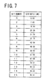
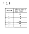
- Comparison processing for repeating a fixed number of processing operations is included in each of the processing operations at steps P1, P4 and P5. Such processing can be reduced by describing a same process in series by a necessary number of times. Therefore, the numbers of times of comparison processing operations at the individual processing operations except repetitive processing operations of the fixed numbers are such as illustrated in FIG. 9.
- the condition wherein the bit allocation processing amount described above exhibits a maximum value is the case wherein the number of repetitions from step P1 to step P2 exhibits a maximum value. This because, since the bit allocation is one-sided to a certain frequency subband, the bit number of the scale factor is reduced while the bit number of the sample is increased and consequently the processing number of times from step P1 to step P2 exhibits a maximum value.
- the bit rate is 192 kbps and the sampling frequency is 48 kHz
- the repetition number exhibits a maximum value when 14 bits are allocated to the frequency subbands 0 to 5, 13 bits are allocated to the frequency subbands 6 to 7 and 0 bits are allocated to the other frequency subbands.
- the processing operations from step P1 to step P2 are repetitively executed by 101 times, and the processing operations from step P5 to step P6 are executed once.
- comparison processing occurs by a total number of 3,501 times.
- the bit allocator 15 which performs such bit allocation processing as described above in the conventional frequency subband encoding apparatus of FIG. 5 is realized, for example, using a microprocessor.
- the processing of the bit allocator includes a large number of comparison processing operations. Therefore, the conventional frequency subband encoding apparatus is disadvantageous in that, in order to encode an audio signal on the predetermined real time basis, a microprocessor and other hardware elements having a high processing capacity are required and a very high cost is required for the apparatus.
- EP-A-0578063 (NEC Corporation)discloses a method and apparatus for allocating quantization bit numbers to a plurality of frequency band signals into which an input signal is divided.
- the method comprises selecting, as a selected subband signal, one of the frequency band signals that has a maximum of a ratio of a maximal signal level to a mask level; allocating to the selected subband signal, as a primary provisional bit number, a maximal quantization bit number allocatable to the selected subband signal; calculating a primary mask to noise ratio of the selected subband signal; incrementing one by one from zero each of temporary bit numbers allocated temporarily to other subband signals of the frequency band signals, meanwhile calculating secondary mask to noise ratios of the other subband signals each time when the temporary bit numbers are incremented by one; allocating the temporary bit numbers to the other subband signals as secondary provisional bit numbers when the secondary mask to noise ratios individually exceed the primary mask to noise ratio; summing up the primary and the secondary provisional bit numbers into a sum; comparing the sum with a
- a frequency subband encoding apparatus comprising a subband filter for dividing a digital audio signal into a plurality of frequency subbands, a signal to mask level ratio calculator for calculating mask levels for the individual frequency subbands from the digital audio signal based on a psychoacoustic model, detecting signal levels of the individual frequency subbands from samples of the frequency subbands and outputting signal to mask level ratios which are ratios between the signal levels and the mask levels for the individual frequency subbands, characterised in that the apparatus further comprises a bit allocator for determining a reference noise to mask level ratio NMR which is a value obtained by subtracting, from a signal to mask level ratio of the entire frequency band, a signal to noise ratio calculated from a reference bit number to be allocated to the frequency subband which exhibits a maximum signal to mask level ratio and adjusting the reference NMR to perform bit allocation, and a quantizer for quantizing samples of the individual frequency subbands with quantization step numbers calculated from bit allocation amounts to the individual
- the bit allocator temporarily allocates, to those of the frequency subbands which have higher signal to mask level ratios than the reference NMR, bit numbers corresponding to differences between the signal to mask level ratios and the reference NMR and then adjusts the reference NMR to perform bit allocation repetitively until a remaining bit number after the temporary bit allocation exhibits a minimum value.
- a reference NMR is calculated from a maximum SMR and a reference bit number, and temporary bit allocation is performed based on the reference NMR. Then, by adjusting the reference NMR, temporary bit allocation is performed until an allowable bit number is reduced to a minimum value. Thereafter, allocation processing of a remaining bit number or releasing processing of an insufficient bit number is performed.
- the number of comparison processing operations in bit allocation processing can be reduced comparing with that required with the conventional frequency subband encoding apparatus. According to a preferred form, the number of comparison processing operations can be reduced from 3,501 with the conventional frequency subband encoding apparatus to 272 with the frequency subband encoding apparatus of the present invention.
- the frequency subband encoding apparatus includes, similarly to the conventional frequency subband encoding apparatus described hereinabove with reference to FIG. 5, a subband filter 1, a scale factor determinator 2, a quantizer 3, an SMR calculator 4 for outputting, for each of frequency subbands, a signal to mask level ratio (SMR) which is a ratio between a signal level of the frequency subband and a mask level for the frequency subband based a psychoacoustic model, a bit allocator 5 for determining a bit allocation amount, and a multiplexer 6.
- SMR signal to mask level ratio
- the present frequency subband encoding apparatus is different from the conventional frequency subband encoding apparatus of FIG. 5 only in that the bit allocator 5 operates in a manner different from that of the bit allocator 15. Therefore, only operation of the bit allocator 5 will be described in detail below.
- FIGS. 2(a), 2(b) and 3 A procedure of bit allocation processing of the bit allocator 5 is illustrated in FIGS. 2(a), 2(b) and 3.
- step S1 a frequency subband which exhibits a maximum signal to mask level ratio (SMR) among 32 frequency subbands is detected.
- SMR signal to mask level ratio
- a value obtained by subtracting, from the maximum SMR, an S/N ratio which corresponds to a number of bits (reference bit number) to be allocated to the frequency subband which has the maximum SMR is determined as reference NMR.
- bit numbers corresponding to the differences of the SMR values from the reference NMR are temporarily allocated.
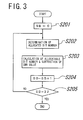
- FIG. 3 Details of the temporary allocation processing are illustrated in FIG. 3.
- step S201 "0" is substituted into a variable SB, and then at step S202, a temporary allocation bit number is determined from the difference of an SMR corresponding to the variable SB from the reference NMR.
- the allocation bit number one of 16 different bit allocation levels is selected based on the relationship between the S/N ratio and the bit number illustrated in FIG. 7. Consequently, by employing the present searching technique, an allocated bit number can be determined by five comparison processing operations.
- step S203 a used bit number determined from the thus determined bit number is subtracted from an allocatable bit number, and an SMR determined from the allocated bit number is subtracted from the SMR of the frequency subband.
- step S204 the variable SB is incremented by one, and then at step S205, it is discriminated whether or not the variable SB is equal to 32. If the variable SB is not equal to 32, then the control sequence returns to step S202, but if the variable SB is equal to 32, then the temporary allocation processing of FIG. 3 is ended and the control sequence returns to the original routine.
- step S4 it is discriminated whether or not the allocatable bit number after such bit allocation as described above is smaller than 0.
- the control sequence advances to step S5, but when the allocatable bit number is smaller than 0, the control sequence advances to step S9.
- step S5 it is discriminated whether or not the reference bit number is equal to 14 which is smaller by one than a maximum allocatable bit number.
- the reference bit number is 14, the temporary allocation processing is ended and the control sequence advances to step S15 illustrated in FIG. 2(b).
- step S5 the control sequence advances to step S6, at which the reference bit number is increased by one step and the reference NMR is calculated again, and then temporary bit allocation is performed. Then at step S7, the variable NEW is substituted into another variable OLD and the allocatable bit number is substituted into the variable NEW. At step S8, it is discriminated whether or not the allocatable bit number is greater than 0. If the allocatable bit number is greater than 0, the control sequence returns to step S5, but otherwise, the control sequence advances to step S13.
- step S9 it is discriminated whether or not the reference bit number is equal to 2 prior by one step to the non-allocated condition. If the reference bit number is equal to 2, then the temporary allocation processing is ended and the control sequence advances to step S15 of FIG. 2(b). If the reference bit number is not equal to 2 at step S9, then the control sequence advances to step S10, at which the reference bit number is decreased by one step and the reference NMR is calculated again, and then bit releasing is performed. Then at step S11, the released bit number is added to the allocatable bit number, and at step S12, it is discriminated whether or not the allocatable bit number is equal to or greater than 0.
- step S13 the variable OLD and an absolute value of the variable NEW are compared with each other, and if the absolute value of the variable NEW is greater, then the variable OLD is substituted into the remaining bit number and also the bit allocation information is returned to the value of the variable OLD. Thereafter, the control sequence advances to step S15 of FIG. 2(b).
- step S15 the remaining bit number is checked. If the remaining bit number is smaller than 0, then the control sequence advances to step S16, but if the remaining bit number is equal to or greater than 0, the control sequence advances to step S19.
- step S16 those frequency subbands to which bits have not been allocated yet are removed from the object of comparison processing of the SMR. Then at step S17, a frequency subband which exhibits a minimum SMR is detected, and the allocated bit number of the frequency subband is decreased by one step.
- step S18 it is discriminated whether or not the allocable bit number is smaller than 0. If the allocatable bit number is smaller than 0, then the control sequence returns to step S17, but if the allocatable bit number is equal to or greater than 0, then the control sequence advances to step S21.
- step 19 it is discriminated whether or not the allocable bit number is smaller than 30.
- the control sequence advances to step S21, but when the allocatable bit number is equal to or greater than 30, the control sequence advances to step S20.
- step S20 a frequency subband which exhibits a maximum SMR is detected, and the allocated bit number of the frequency subband is increased by one step, whereafter the control sequence returns to step S19.
- step S21 it is discriminated whether or not the allocatable bit number is smaller than 12. If the allocatable bit number is smaller than 12, then the processing is ended. On the contrary if the allocatable bit number is equal to or greater than 12, then the control sequence advances to step S22, at which those frequency subbands to which bits have not been allocated yet are removed from the object of the comparison processing of the SMR. Then at step S23, a frequency subband which exhibits a maximum SMR is detected, and the allocated bit number of the frequency subband is increased by one step. Subsequently at step S24, it is discriminated whether or not the remaining bit number is smaller than 12. If the remaining bit number is smaller than 12, then the processing is ended, but on the contrary if the remaining bit number is equal to or greater than 12, then the control sequence returns to step S23.
- FIG. 4 illustrates comparison operation numbers which are comparison processing amounts of the various processing operations in the present embodiment.
- the comparison operation numbers in the present embodiment are calculated in the condition in which the comparison calculation amount by the conventional frequency subband encoding apparatus exhibits a maximum value.
- the reference bit number is selected to be 9 bits.
- step S4 the control sequence advances to step S5, and the processing operations at steps S5 to S8 are repeated by five times.
- step S15 the control sequence advances to step S19, and from step S19, the control sequence advances to step S20.
- the control sequence advances from step S19 to step S21, from which the control sequence comes to an end. Consequently, the total number of comparison operations is 272. Meanwhile, the result of the bit allocation processing is the same as that obtained by the conventional frequency subband encoding apparatus.
Landscapes
- Engineering & Computer Science (AREA)
- Computer Networks & Wireless Communication (AREA)
- Signal Processing (AREA)
- Compression, Expansion, Code Conversion, And Decoders (AREA)
Claims (4)
- Dispositif de codage en sous-bandes de fréquences comprenant :caractérisé en ce que le dispositif comprend en outre :un filtre de sous-bandes (1) pour diviser un signal audio numérique (7) en une pluralité de sous-bandes de fréquences ;un calculateur de rapport niveau de signal/niveau de masquage (4) pour calculer des niveaux de masquage pour les sous-bandes de fréquences individuelles à partir du signal audio numérique (7) en se basant sur un modèle psychoacoustique, détecter les niveaux de signal des sous-bandes de fréquences individuelles à partir d'échantillons des sous-bandes de fréquences et délivrer les rapports niveau de signal/niveau de masquage qui sont les rapports entre les niveaux de signal et les niveaux de masquage pour les sous-bandes de fréquences individuelles ;un système d'allocation de bits (5) pour déterminer un rapport de référence niveau de bruit/niveau de masquage RMN qui est une valeur obtenue par soustraction à partir d'un rapport niveau de signal/niveau de masquage de toute la bande de fréquences, d'un rapport signal/bruit calculé à partir d'un nombre de bits de référence devant être alloué à la sous-bande de fréquences qui présente un rapport niveau de signal/niveau de masquage maximal et en ajustant la RMN de référence pour effectuer l'allocation de bits ; etun quantificateur (3) pour quantifier des échantillons des sous-bandes de fréquences individuelles avec des nombres d'étapes de quantification calculés à partir de quantités d'allocation de bits pour les sous-bandes de fréquences individuelles.
- Dispositif de codage de sous-bandes de fréquences selon la revendication 1, caractérisé en ce que ledit système d'allocation de bits (5) alloue temporairement, à celles des sous-bandes de fréquences qui ont un rapport niveau de signal/niveau de masquage supérieur à la RMN de référence, des nombres de bits correspondant aux différences entre les rapports niveau de signal/niveau de masquage et la RMN de référence puis ajuste la RMN de référence pour effectuer une allocation de bits de manière répétée jusqu'à ce qu'un nombre de bits restant après l'allocation de bits temporaire présente une valeur minimale.
- Dispositif de codage de sous-bandes de fréquences selon la revendication 1 ou 2, caractérisé en ce qu'une limite à un nombre de bits pouvant être alloué à une trame du signal audio numérique (7) et une limite à des nombres de bits maximaux pouvant être alloués aux sous-bandes de fréquences individuelles sont déterminées à l'avance.
- Dispositif de codage de sous-bandes de fréquences selon la revendication 4, caractérisé en ce que le signal audio numérique (7) présente un débit binaire de 192 kbps et en ce qu'une fréquence d'échantillonnage pour le signal audio numérique est de 48 kHz, la limite au nombre de bits pouvant être alloué à une trame est de 1536 bits et la limite aux nombres maximaux de bits pouvant être alloués aux sous-bandes de fréquences individuelles est de 15 bits.
Applications Claiming Priority (3)
| Application Number | Priority Date | Filing Date | Title |
|---|---|---|---|
| JP22988994 | 1994-09-26 | ||
| JP6229889A JP2778482B2 (ja) | 1994-09-26 | 1994-09-26 | 帯域分割符号化装置 |
| JP229889/94 | 1994-09-26 |
Publications (3)
| Publication Number | Publication Date |
|---|---|
| EP0703677A2 EP0703677A2 (fr) | 1996-03-27 |
| EP0703677A3 EP0703677A3 (fr) | 1997-06-18 |
| EP0703677B1 true EP0703677B1 (fr) | 1999-06-09 |
Family
ID=16899310
Family Applications (1)
| Application Number | Title | Priority Date | Filing Date |
|---|---|---|---|
| EP95306733A Expired - Lifetime EP0703677B1 (fr) | 1994-09-26 | 1995-09-25 | Codeur perceptuel en sous-bandes |
Country Status (4)
| Country | Link |
|---|---|
| US (1) | US5588024A (fr) |
| EP (1) | EP0703677B1 (fr) |
| JP (1) | JP2778482B2 (fr) |
| DE (1) | DE69510147T2 (fr) |
Families Citing this family (20)
| Publication number | Priority date | Publication date | Assignee | Title |
|---|---|---|---|---|
| KR970011727B1 (en) * | 1994-11-09 | 1997-07-14 | Daewoo Electronics Co Ltd | Apparatus for encoding of the audio signal |
| AU5663296A (en) | 1995-04-10 | 1996-10-30 | Corporate Computer Systems, Inc. | System for compression and decompression of audio signals fo r digital transmission |
| US6700958B2 (en) * | 1995-04-10 | 2004-03-02 | Starguide Digital Networks, Inc. | Method and apparatus for transmitting coded audio signals through a transmission channel with limited bandwidth |
| JP2776300B2 (ja) * | 1995-05-31 | 1998-07-16 | 日本電気株式会社 | 音声信号処理回路 |
| WO1997007606A1 (fr) * | 1995-08-16 | 1997-02-27 | Starguide Digital Networks, Inc. | Affectation dynamique des bandes de frequences pour la transmission de signaux audio et d'un signal video |
| JP2000514929A (ja) * | 1995-09-01 | 2000-11-07 | スターガイド デジタル ネットワークス,インコーポレイティド | オーディオファイル配信および生成システム |
| JPH09101799A (ja) * | 1995-10-04 | 1997-04-15 | Sony Corp | 信号符号化方法及び装置 |
| US5956674A (en) * | 1995-12-01 | 1999-09-21 | Digital Theater Systems, Inc. | Multi-channel predictive subband audio coder using psychoacoustic adaptive bit allocation in frequency, time and over the multiple channels |
| US7194757B1 (en) | 1998-03-06 | 2007-03-20 | Starguide Digital Network, Inc. | Method and apparatus for push and pull distribution of multimedia |
| US6160797A (en) | 1998-04-03 | 2000-12-12 | Starguide Digital Networks, Inc. | Satellite receiver/router, system, and method of use |
| US8284774B2 (en) | 1998-04-03 | 2012-10-09 | Megawave Audio Llc | Ethernet digital storage (EDS) card and satellite transmission system |
| DE69932861T2 (de) * | 1999-10-30 | 2007-03-15 | Stmicroelectronics Asia Pacific Pte Ltd. | Verfahren zur kodierung eines audiosignals mit einem qualitätswert für bit-zuordnung |
| US7075506B2 (en) * | 2000-02-25 | 2006-07-11 | Texas Instruments Incorporated | Spatial-temporal multiplexing |
| US6745162B1 (en) * | 2000-06-22 | 2004-06-01 | Sony Corporation | System and method for bit allocation in an audio encoder |
| WO2002069073A2 (fr) * | 2000-11-13 | 2002-09-06 | Starguide Digital Networks, Inc. | Carte ethernet de stockage numerique (eds) et systeme de transmission par satellite comprenant une possibilite de telecopie |
| JP2002196792A (ja) * | 2000-12-25 | 2002-07-12 | Matsushita Electric Ind Co Ltd | 音声符号化方式、音声符号化方法およびそれを用いる音声符号化装置、記録媒体、ならびに音楽配信システム |
| WO2004107318A1 (fr) * | 2003-05-27 | 2004-12-09 | Koninklijke Philips Electronics N.V. | Codage audio |
| JP4573670B2 (ja) * | 2005-02-25 | 2010-11-04 | ティーオーエー株式会社 | 符号化装置、符号化方法、復号化装置及び復号化方法 |
| US8774308B2 (en) * | 2011-11-01 | 2014-07-08 | At&T Intellectual Property I, L.P. | Method and apparatus for improving transmission of data on a bandwidth mismatched channel |
| US8781023B2 (en) * | 2011-11-01 | 2014-07-15 | At&T Intellectual Property I, L.P. | Method and apparatus for improving transmission of data on a bandwidth expanded channel |
Family Cites Families (5)
| Publication number | Priority date | Publication date | Assignee | Title |
|---|---|---|---|---|
| US5367608A (en) * | 1990-05-14 | 1994-11-22 | U.S. Philips Corporation | Transmitter, encoding system and method employing use of a bit allocation unit for subband coding a digital signal |
| JP2906646B2 (ja) * | 1990-11-09 | 1999-06-21 | 松下電器産業株式会社 | 音声帯域分割符号化装置 |
| US5365553A (en) * | 1990-11-30 | 1994-11-15 | U.S. Philips Corporation | Transmitter, encoding system and method employing use of a bit need determiner for subband coding a digital signal |
| TW235392B (fr) * | 1992-06-02 | 1994-12-01 | Philips Electronics Nv | |
| JP2976701B2 (ja) * | 1992-06-24 | 1999-11-10 | 日本電気株式会社 | 量子化ビット数割当方法 |
-
1994
- 1994-09-26 JP JP6229889A patent/JP2778482B2/ja not_active Expired - Fee Related
-
1995
- 1995-09-25 EP EP95306733A patent/EP0703677B1/fr not_active Expired - Lifetime
- 1995-09-25 US US08/533,100 patent/US5588024A/en not_active Expired - Lifetime
- 1995-09-25 DE DE69510147T patent/DE69510147T2/de not_active Expired - Fee Related
Also Published As
| Publication number | Publication date |
|---|---|
| US5588024A (en) | 1996-12-24 |
| EP0703677A2 (fr) | 1996-03-27 |
| JP2778482B2 (ja) | 1998-07-23 |
| JPH0895598A (ja) | 1996-04-12 |
| DE69510147T2 (de) | 2000-03-02 |
| DE69510147D1 (de) | 1999-07-15 |
| EP0703677A3 (fr) | 1997-06-18 |
Similar Documents
| Publication | Publication Date | Title |
|---|---|---|
| EP0703677B1 (fr) | Codeur perceptuel en sous-bandes | |
| US5732391A (en) | Method and apparatus of reducing processing steps in an audio compression system using psychoacoustic parameters | |
| EP0267344B1 (fr) | Procédé de codage multivitesse de signaux et dispositif de mise en oeuvre dudit procédé | |
| EP0578063B1 (fr) | Allocation du nombre de bits de quantification par sélection préalable d'une sous-bande ayant un rapport signal/masquage maximum | |
| CA2164964C (fr) | Affectation hybride adaptative pour codeur et decodeur audio | |
| US8407043B2 (en) | Computationally efficient audio coder | |
| EP0455738B2 (fr) | Codeur, decodeur et codeur/decodeur par transformees a faible debit binaire pour applications audio de haute qualite | |
| EP0663740A2 (fr) | Appareil pour codifier de façon adaptative les signaux audio-numériques provenant d'une pluralité de canaux | |
| EP0217017B1 (fr) | Procédé de codage d'un signal et système de réalisation de ce procédé | |
| EP0721257A1 (fr) | Allocation de bits pour un codeur audio basée sur l'entropie perceptuelle | |
| EP0772925B1 (fr) | Quantification non lineaire d'un signal d'information | |
| US6466912B1 (en) | Perceptual coding of audio signals employing envelope uncertainty | |
| US5761636A (en) | Bit allocation method for improved audio quality perception using psychoacoustic parameters | |
| EP1175670B2 (fr) | Mise en oeuvre d'une quantification a gain adaptatif et de longueurs de symboles non uniformes pour codage audio | |
| US20040225495A1 (en) | Encoding apparatus, method and program | |
| JP2000151413A (ja) | オーディオ符号化における適応ダイナミック可変ビット割り当て方法 | |
| EP0746115A2 (fr) | Circuit de traitement de signal audio pour codage à sous-bandes | |
| EP0589140B1 (fr) | Procédé d'attribution des bits en codage par sous-bandes | |
| JPH08307281A (ja) | 非線形量子化方法及び非線形逆量子化方法 | |
| JP3465341B2 (ja) | オーディオ信号符号化方法 | |
| JPH0750589A (ja) | サブバンド符号化装置 | |
| EP1176743B1 (fr) | Procédé de quantification et déquantification non linéaire d'un signal d'information | |
| KR100287861B1 (ko) | 디지탈 오디오 스테레오 모드에서의 각 채널 비균등 비트할당 장치 및 방법 | |
| JPH07154268A (ja) | 帯域分割符号化装置 | |
| HK1013897A1 (en) | Encoding and decoding of a wideband digital information signal |
Legal Events
| Date | Code | Title | Description |
|---|---|---|---|
| PUAI | Public reference made under article 153(3) epc to a published international application that has entered the european phase |
Free format text: ORIGINAL CODE: 0009012 |
|
| AK | Designated contracting states |
Kind code of ref document: A2 Designated state(s): DE FR GB |
|
| PUAL | Search report despatched |
Free format text: ORIGINAL CODE: 0009013 |
|
| AK | Designated contracting states |
Kind code of ref document: A3 Designated state(s): DE FR GB |
|
| 17P | Request for examination filed |
Effective date: 19970507 |
|
| 17Q | First examination report despatched |
Effective date: 19970725 |
|
| GRAG | Despatch of communication of intention to grant |
Free format text: ORIGINAL CODE: EPIDOS AGRA |
|
| GRAG | Despatch of communication of intention to grant |
Free format text: ORIGINAL CODE: EPIDOS AGRA |
|
| GRAH | Despatch of communication of intention to grant a patent |
Free format text: ORIGINAL CODE: EPIDOS IGRA |
|
| GRAH | Despatch of communication of intention to grant a patent |
Free format text: ORIGINAL CODE: EPIDOS IGRA |
|
| GRAA | (expected) grant |
Free format text: ORIGINAL CODE: 0009210 |
|
| AK | Designated contracting states |
Kind code of ref document: B1 Designated state(s): DE FR GB |
|
| REF | Corresponds to: |
Ref document number: 69510147 Country of ref document: DE Date of ref document: 19990715 |
|
| ET | Fr: translation filed | ||
| PLBE | No opposition filed within time limit |
Free format text: ORIGINAL CODE: 0009261 |
|
| STAA | Information on the status of an ep patent application or granted ep patent |
Free format text: STATUS: NO OPPOSITION FILED WITHIN TIME LIMIT |
|
| 26N | No opposition filed | ||
| REG | Reference to a national code |
Ref country code: GB Ref legal event code: IF02 |
|
| REG | Reference to a national code |
Ref country code: GB Ref legal event code: 732E |
|
| REG | Reference to a national code |
Ref country code: FR Ref legal event code: TP |
|
| PGFP | Annual fee paid to national office [announced via postgrant information from national office to epo] |
Ref country code: FR Payment date: 20080915 Year of fee payment: 14 |
|
| PGFP | Annual fee paid to national office [announced via postgrant information from national office to epo] |
Ref country code: DE Payment date: 20081002 Year of fee payment: 14 |
|
| PGFP | Annual fee paid to national office [announced via postgrant information from national office to epo] |
Ref country code: GB Payment date: 20081001 Year of fee payment: 14 |
|
| GBPC | Gb: european patent ceased through non-payment of renewal fee |
Effective date: 20090925 |
|
| REG | Reference to a national code |
Ref country code: FR Ref legal event code: ST Effective date: 20100531 |
|
| PG25 | Lapsed in a contracting state [announced via postgrant information from national office to epo] |
Ref country code: FR Free format text: LAPSE BECAUSE OF NON-PAYMENT OF DUE FEES Effective date: 20090930 Ref country code: DE Free format text: LAPSE BECAUSE OF NON-PAYMENT OF DUE FEES Effective date: 20100401 |
|
| PG25 | Lapsed in a contracting state [announced via postgrant information from national office to epo] |
Ref country code: GB Free format text: LAPSE BECAUSE OF NON-PAYMENT OF DUE FEES Effective date: 20090925 |