EP0703684B1 - Réseau de transmission point à multipoint à accès multiples par répartition temporelle - Google Patents
Réseau de transmission point à multipoint à accès multiples par répartition temporelle Download PDFInfo
- Publication number
- EP0703684B1 EP0703684B1 EP95402110A EP95402110A EP0703684B1 EP 0703684 B1 EP0703684 B1 EP 0703684B1 EP 95402110 A EP95402110 A EP 95402110A EP 95402110 A EP95402110 A EP 95402110A EP 0703684 B1 EP0703684 B1 EP 0703684B1
- Authority
- EP
- European Patent Office
- Prior art keywords
- frames
- station
- local
- une
- central station
- Prior art date
- Legal status (The legal status is an assumption and is not a legal conclusion. Google has not performed a legal analysis and makes no representation as to the accuracy of the status listed.)
- Expired - Lifetime
Links
- 230000005540 biological transmission Effects 0.000 title claims description 25
- 238000005259 measurement Methods 0.000 claims description 17
- 238000005070 sampling Methods 0.000 claims description 5
- 235000021183 entrée Nutrition 0.000 description 27
- 238000012360 testing method Methods 0.000 description 17
- 230000033764 rhythmic process Effects 0.000 description 13
- 238000000034 method Methods 0.000 description 10
- 230000001934 delay Effects 0.000 description 8
- 238000002310 reflectometry Methods 0.000 description 8
- 238000006243 chemical reaction Methods 0.000 description 6
- 238000010586 diagram Methods 0.000 description 5
- 230000000630 rising effect Effects 0.000 description 4
- 230000006835 compression Effects 0.000 description 2
- 238000007906 compression Methods 0.000 description 2
- 238000012546 transfer Methods 0.000 description 2
- 238000004891 communication Methods 0.000 description 1
- 238000010276 construction Methods 0.000 description 1
- 230000003247 decreasing effect Effects 0.000 description 1
- 230000009977 dual effect Effects 0.000 description 1
- 238000000691 measurement method Methods 0.000 description 1
- 230000003287 optical effect Effects 0.000 description 1
- 230000000737 periodic effect Effects 0.000 description 1
- 230000001360 synchronised effect Effects 0.000 description 1
- 230000002123 temporal effect Effects 0.000 description 1
- 238000011144 upstream manufacturing Methods 0.000 description 1
Images


Classifications
-
- H—ELECTRICITY
- H04—ELECTRIC COMMUNICATION TECHNIQUE
- H04J—MULTIPLEX COMMUNICATION
- H04J3/00—Time-division multiplex systems
- H04J3/02—Details
- H04J3/06—Synchronising arrangements
- H04J3/0635—Clock or time synchronisation in a network
- H04J3/0682—Clock or time synchronisation in a network by delay compensation, e.g. by compensation of propagation delay or variations thereof, by ranging
Definitions
- the invention relates to a point-to-point transmission network.
- multipoint with multiple access by distribution time ion comprising a central station and a plurality of stations local.
- the central station transmits so-called descending frames containing data intended at local stations, each downlink frame having a fixed duration and including data intended for all local stations, or separate data respectively for the different local stations.
- Each local station transmits so-called uplink subframes, each rising sub-frame having a fixed duration and comprising data transmitted by this single local station and which are intended for the central station.
- Subframes are sent by local stations so as to be distributed in the time without overlapping, to constitute a so-called frame uplink.
- the propagation time between a local station and the central station is not uniform for all stations.
- Measuring means of transmission times determine the times of transmission from each local station, so that the subframes transmitted by all local stations are received by the central station without overlapping.
- Each local station has means for measuring propagation delays which determine the delay of propagation between this local station and the station central, and deduce the times when the local station can transmit a subframe, so that the station control unit receives a frame consisting of s subframes that do not overlap.
- the stations local are connected to a private telephone exchange and are distributed within the boundaries of a building.
- the deadline for round trip propagation is therefore of the order of 10 microseconds.
- the frames have a duration fixed at 125 microseconds, which corresponds to the sampling period of a conventional telephone channel in a network digital telephone. It is possible to leave free a interval of the order of 10 microseconds, in a frame of 125 microseconds, without significantly decreasing network transmission efficiency. Such a duration of the free interval is quite sufficient for a network limited to one building.
- this process cannot be implemented in an extended network over longer distances, such as than a public telecommunications network. Indeed, such network is connected to local stations located at much greater distances, up to 10 km. The round trip delay then reaches values on the order of 100 microseconds. He is not possible to sacrifice most of the duration of frames to leave a free interval with a duration of around 100 microseconds.
- Document EP 0229 684 describes a network of point-to-multipoint transmission with multiple access by time distribution, in which data is transmitted from a central station to local stations in multi-frames comprising a plurality of frames intended respectively for local stations.
- Each multiframe has a single free interval allowing transmission delay measures and reflectometry.
- Data is transmitted from stations to a central station in the form of multiframes having a plurality of frames and a single interval free allowing measurements of transmission times and reflectometry measurements, each frame comprising sub-frames transmitted respectively by the local stations, each local station transmitting one or more of the subframes contained in a frame.
- the free interval in each multiframe can be double the maximum delay round trip propagation, without causing reduction important to the network transmission efficiency, since this free interval is much less frequent than if it existed in each frame.
- this document describes means for form multi-frames leaving a single free interval in each multi-frame. These means operate a compression of the data to be transmitted.
- the object of the invention is to propose a network of point-to-multi-point transmission in which the station central and local stations include means for transmit multiframes comprising a single free interval, by operating according to a process different from the temporal compression.
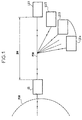
- Figure 1 shows the block diagram of a example of a network according to the invention.
- the central station transmits data intended for all stations.
- the central station can transmit separate data for different stations local, by assigning each frame of a multiframe to a given local station.
- the central station CS communicates on the one hand with a PSN public telecommunications network and secondly with s stations called local LS1, LS2, LS3, ..., LSs, via a passive PON optical network carrying signals in both ways.
- CS central station transmits data intended for all local stations LS1, ..., LSs, and each transmits data to the central station CS.
- the central station CS exchanges signals with the public telecommunications network PSN in the form of asynchronous transfer mode cells at average rate of a cell every 125 microseconds, or a multiple of this rhythm, this rhythm corresponding to the standard period for channel sampling telephone in digital telephone networks.
- each local station LS1, ..., LSs exchanges data with a terminal, not shown, which can be a multimedia microcomputer, for example, at medium speed of a cell every 125 microseconds for example.
- Local stations LS1, ..., LSs are located at various distances from the central station CS.
- the farthest local station, LS1 is located one distance DM of the order of 10 km, which implies a delay of round trip propagation of around 100 microseconds.
- DM the order of 10 km, which implies a delay of round trip propagation of around 100 microseconds.
- FIG. 2 represents the structure of a downlink multiframe MF transmitted by the central station CS, according to the invention.
- Each MF multiframe has a TMF duration which is equal to a multiple of the sampling period of a telephone channel, to simplify the construction of the network.
- the number N can be equal to the number s of local stations, but it is not essential.
- the frames F1, ..., FN are followed by a free interval DMW having a fixed duration TW.
- each frame depends on the application in question. If the central station transmits different data for different local stations, each frame, such as the frame Fj, is subdivided into sub-frames, not shown, intended for different stations local LS1, ..., LSs. If the central station CS transmits common data for all local stations, these data can be distributed in any way in the frames F1, ..., FN. In the latter case, the frame F1 has a multiframe header, MFH, and a payload PL1, while all the other frames F2, ..., FN only have a chargeable charge. The MFH header allows you to manage the data transmitted in the paying charge of all frames F1, ..., FN composing the MF multiframe.
- each frame comprises 2356 bytes, the first F1 frame comprising a 16-byte MFH header and a 2340 PL1 payload bytes.
- FIG. 3 represents the structure of a rising multiframe MF ′.
- the duration of this free interval being much greater than 100 microseconds, it allows measurements of transmission delays for a maximum distance DM greater than 10 km.
- Each local station LS1, ...., LSs transmits one or more subframes depending on the quantity information that it must transmit, the allocation of these subframes being fixed for the entire duration of a communication.
- the instant when a station transmits its subframe or its subframes is determined by means of measuring propagation delays, so that when arriving at the central station CS, the subframes SF1, ..., SF43 are spread over time without overlapping and constituting a continuous packet of data.
- each subframe for example the SFi subframe, consists of a length preamble set equal to one byte, including a guard interval, and of a payload Ci1 made up of 53 bytes which can be samples from multiple phone channels classics or the 53 bytes BY1, ..., BY53 of a cell with asynchronous transfer mode.
- a local station LSi receives a suite of data sources of cells Ci1, ..., CiN ', ..., successive, at the average rate of a cell every 125 ⁇ s, these cells are transported respectively in the frames F'1, ..., F'N 'of the multiframe MF '.
- This transmission network provides good efficiency transmission, despite the existence of free intervals allowing measurements of transmission times including durations are around 100 ⁇ s, because these intervals free are repeated with a period which is a multiple of the duration of a frame, which reduces the importance relative free intervals to data transmitted. For example, if each multiframe is made up 32 frames each having a duration of 125 microseconds, and if the duration of the free interval is 100 microseconds, free intervals occupy only 2.4% of the total duration.
- the process used to form the multiframes downlink MF and to form the upstream multiframe MF ' is to underuse the capacity of each source of data, that is, ask it to provide only one fewer data packets than it could provide for the duration of a multiframe.
- FIG. 4 represents a chronogram illustrating the process of underutilizing the capacity of a source of data.
- This data source has a capacity providing a continuous sequence of bytes with a fixed binary rhythm H. In fact, it is used to provide frames F1c, F2c, F3c, ..., FNc including n-m bytes, two successive frames being separated by a free interval corresponding to m bytes.
- a multiframe is formed by concatenating N frames F1c, ..., FNc for constitute a continuous sequence of frames F1d, ..., FNd having the same binary rhythm H but which are shifted in the time with respect to frames F1c, ..., FNc, so that gather in a single free interval the N intervals each corresponding to m bytes.
- FIG. 5 represents the block diagram of a exemplary embodiment of means for transmitting multi-frames by under-using the capacity of a source of data and keeping the same bit rate.
- This device can be used either to emit multi-frames from a central station to the stations local, or from a local station to a station Central.
- This exemplary embodiment comprises: a device 31 which is a classic weft forming device, having an input terminal 16 connected to a data source, and an output providing F1c, ..., FNc, each comprising n-m bytes, with a binary rhythm H, two successive frames being separated by an interval free corresponding to m bytes; and a device 30 of time offset, to form multi-frames.
- a device 31 which is a classic weft forming device, having an input terminal 16 connected to a data source, and an output providing F1c, ..., FNc, each comprising n-m bytes, with a binary rhythm H, two successive frames being separated by an interval free corresponding to m bytes; and a device 30 of time offset, to form multi-frames.
- the memory 27 has a capacity corresponding to at least q bytes, these being stored byte by byte.
- the 26 conversion device allows to store in the form bytes the data bits of the frames F1c, ..., FNc.
- the conversion device 28 makes it possible to restore under the form the data read byte by byte in memory 27.
- the time base 24 commands the writing of n-m bytes, at H / 8 rhythm then does not command no writing during a time interval corresponding to m bytes.
- the base of time 25 does not command any reading during an interval of time corresponding to q bytes, then it commands p-q one-byte reads, at H / 8 rhythm.
- F1d, ..., FNd frames are thus offset respectively with respect to the frames F1c, ..., FNc with offsets such as intervals free m existing between these frames are deleted; and such that the frames F1d, ..., FNd form a continuous sequence of bits and are preceded by a single free interval.
- the invention is applicable to any point-to-point network. multipoint, multiple access by time distribution, and especially to those whose data sources are synchronous or plesiochronous.
Landscapes
- Engineering & Computer Science (AREA)
- Computer Networks & Wireless Communication (AREA)
- Signal Processing (AREA)
- Time-Division Multiplex Systems (AREA)
- Small-Scale Networks (AREA)
- Mobile Radio Communication Systems (AREA)
- Radio Relay Systems (AREA)
- Data Exchanges In Wide-Area Networks (AREA)
- Use Of Switch Circuits For Exchanges And Methods Of Control Of Multiplex Exchanges (AREA)
Description
- une station centrale émet des trames d'une durée de 125 microsecondes comportant une pluralité de sous-trames puis une adresse destinée à l'une des stations locales et lui ordonnant d'émettre un message de test, puis un intervalle libre permettant une mesure de délais de propagation; chaque sous-trame contenant des données destinées à une station locale distincte;
- des stations locales émettent chacune à tour de rôle une sous-trame contenant des données à transmettre de cette station locale à la station centrale.
- émettre de la station centrale vers une station locale une adresse désignant cette station locale et lui ordonnant d'émettre un message de test, cette adresse étant insérée dans une trame descendante, à la suite des sous-trames de données, et précédant l'intervalle libre;
- émettre de cette station locale vers la station centrale un message de test dès que cette station locale a reconnu son adresse, l'intervalle libre dans les trames descendantes et l'intervalle libre dans les trames montantes ayant chacun une durée qui est choisie suffisante pour que le message de test tombe toujours dans ces intervalles quelle que soit la distance à laquelle est située une station locale, afin d'éviter une collision avec des données;
- recevoir le message de test dans la station centrale et le réémettre immédiatement, cette réémission ayant lieu dans l'intervalle libre d'une trame descendante;
- recevoir le message de test dans la station locale qui l'a émise, déterminer la durée de la propagation entre la station locale et la station centrale, et en déduire les instants d'émission des sous-trames de cette station locale.
chaque station locale comportant des moyens pour émettre des multitrames dites montantes comportant une pluralité de trames montantes et un seul intervalle libre ayant une largeur permettant d'effectuer des mesures, chaque trame montante comportant une pluralité de sous-trames dites montantes, chaque sous-trame montante ayant une durée fixée et comportant des données émises par cette seule station locale et destinée à la station centrale, les sous-trames montantes étant émises à des instants prédéterminés par des moyens de mesure de délais de transmission, de telle manière que les sous-trames émises par toutes les stations locales sont reçues par la station centrale en se répartissant dans le temps sans se chevaucher, et en constituant une trame dite montante;
la station centrale comportant des moyens pour émettre des multitrames dites descendantes comportant une pluralité de trames descendantes et un seul intervalle libre ayant une durée permettant d'effectuer des mesures;
caractérisé en ce que, dans la station centrale et/ou au moins une station locale, les moyens pour émettre des multitrames comportent :
- des moyens pour prélever à une source de données une suite de paquets de données, deux paquets consécutifs étant séparés par un intervalle libre; et pour insérer chaque paquet dans une trame, deux trames consécutives étant séparées d'un intervalle libre;
- et des moyens de décalage temporel pour insérer un nombre prédéterminé de trames dans une multitrame, en décalant temporellement ces trames pour supprimer les intervalles libres existant entre ces trames, et constituer ainsi une multitrame comportant une seule suite continue de trames décalées et un seul intervalle libre.
- la figure 1 représente le schéma synoptique d'un exemple de réseau selon l'invention;
- la figure 2 représente schématiquement une multitrame descendante et l'une des trames la composant;
- la figure 3 représente schématiquement une multitrame montante, une des trames la composant, et une sous-trame composant l'une de ces trames;
- la figure 4 représente un chronogramme illustrant le fonctionnement de moyens pour émettre des multitrames, en sous-utilisant la capacité d'une source de données, et en conservant son débit binaire;
- la figure 5 représente le schéma synoptique d'un exemple de réalisation de ces moyens.
- une borne d'entrée 20 recevant un signal d'horloge H au rythme binaire des données des trames F1c, ..., FNc;
- une borne d'entrée 21 revevant un signal de synchronisation S au rythme des multitrames;
- une borne d'entrée 22 recevant les trames de données F1c, ..., FNc, sous forme série;
- une borne de sortie 29 fournissant une multitrame constituées de trames F1d, ..., FNd et d'un intervalle libre correspondant à 9 octets;
- un diviseur de fréquence par huit 23, ayant une entrée d'horloge reliée à la borne d'entrée 20, une entrée de synchronisation reliée à la borne d'entrée 21, et trois sorties;
- un dispositif 26 de conversion série-parallèle ayant une entrée de données reliée à la borne d'entrée 22, une première entrée d'horloge reliée à la borne d'entrée 20, une seconde entrée d'horloge reliée à une première sortie du diviseur 23 fournissant un signal d'horloge au rythme H/8 des octets des trames F1c, ..., FNc, et une sortie;
- une mémoire vive 27 à double accès, ayant une entrée de données reliée à la sortie du dispositif 26, une entrée de commande d'écriture, une entrée de commande de lecture, et une sortie;
- un dispositif 28 de conversion parallèle-série, ayant une entrée de données reliée à la sortie de la mémoire 27, une première entrée d'horloge reliée à la borne d'entrée 20, une seconde entrée d'horloge reliée à une seconde sortie du diviseur 23 fournissant un signal d'horloge au rythme H/8 qui est le rythme des octets des trames F1d, ..., FNd, et une sortie reliée à la borne de sortie 29;
- une base de temps d'écriture, 24, ayant une entrée d'horloge reliée à une troisième sortie du diviseur 23 et fournissant un signal d'horloge au rythme H/8 des octets des trames F1c, ..., FNc, une entrée de synchronisation reliée à la borne d'entrée 21, et une sortie reliée à l'entrée de commande d'écriture de la mémoire 27;
- une base de temps de lecture, 25, ayant une entrée d'horloge reliée à la seconde sortie du diviseur 23 fournissant un signal d'horloge au rythme H/8, une entrée de synchronisation reliée à la borne d'entrée 21, et une sortie reliée à l'entrée de commande de lecture de la mémoire 27.
Claims (1)
- Réseau de transmission point à multipoint à accès multiple par répartition temporelle, comportant une station centrale (CS) et une pluralité de stations locales (LS1, ..., LSs);
chaque station locale (LS1, ..., LSs) comportant des moyens (14;30) pour émettre des multitrames (MF') dites montantes comportant une pluralité de trames montantes (F'1, ..., F'N') et un seul intervalle libre (DMW') ayant une largeur permettant d'effectuer des mesures, chaque trame montante (F1') comportant une pluralité de sous-trames (SFi) dites montantes, chaque sous-trame montante ayant une durée fixée et comportant des données émises par cette seule station locale et destinée à la station centrale, les sous-trames montantes étant émises à des instants prédéterminés par des moyens de mesure de délais de transmission, de telle manière que les sous-trames émises par toutes les stations locales sont reçues par la station centrale en se répartissant dans le temps sans se chevaucher, et en constituant une trame dite montante (TMF');
la station centrale comportant des moyens (14; 30) pour émettre des multitrames dites descendantes (MF) comportant une pluralité de trames descendantes (F1, ..., FN) et un seul intervalle libre (DMW) ayant une durée permettant d'effectuer des mesures;
caractérisé en ce que, dans la station centrale (CS) et/ou au moins une station locale (LS1,...,LSs), les moyens pour émettre des multitrames comportent :des moyens (31) pour prélever à une source de données une suite de paquets de données, deux paquets consécutifs étant séparés par un intervalle libre; et pour insérer chaque paquet dans une trame (F1c,...,FNc), deux trames consécutives étant séparées d'un intervalle libre (m) ;et des moyens (30) de décalage temporel pour insérer un nombre prédéterminé de trames dans une multitrame, en décalant temporellement ces trames pour supprimer les intervalles libres (m) existant entre ces trames, et constituer ainsi une multitrame comportant une seule suite continue de trames décalées (F1d,...,FNd) et un seul intervalle libre (q).
Applications Claiming Priority (2)
| Application Number | Priority Date | Filing Date | Title |
|---|---|---|---|
| FR9411401A FR2725093B1 (fr) | 1994-09-23 | 1994-09-23 | Reseau de transmission point a multipoint a acces multiples par repartition temporelle |
| FR9411401 | 1994-09-23 |
Publications (2)
| Publication Number | Publication Date |
|---|---|
| EP0703684A1 EP0703684A1 (fr) | 1996-03-27 |
| EP0703684B1 true EP0703684B1 (fr) | 2002-04-10 |
Family
ID=9467234
Family Applications (1)
| Application Number | Title | Priority Date | Filing Date |
|---|---|---|---|
| EP95402110A Expired - Lifetime EP0703684B1 (fr) | 1994-09-23 | 1995-09-19 | Réseau de transmission point à multipoint à accès multiples par répartition temporelle |
Country Status (10)
| Country | Link |
|---|---|
| US (1) | US5712982A (fr) |
| EP (1) | EP0703684B1 (fr) |
| JP (1) | JP2690474B2 (fr) |
| AT (1) | ATE216160T1 (fr) |
| AU (1) | AU699642B2 (fr) |
| CA (1) | CA2158895C (fr) |
| DE (1) | DE69526295T2 (fr) |
| ES (1) | ES2173942T3 (fr) |
| FR (1) | FR2725093B1 (fr) |
| NZ (1) | NZ272930A (fr) |
Families Citing this family (14)
| Publication number | Priority date | Publication date | Assignee | Title |
|---|---|---|---|---|
| US6665308B1 (en) | 1995-08-25 | 2003-12-16 | Terayon Communication Systems, Inc. | Apparatus and method for equalization in distributed digital data transmission systems |
| US5805583A (en) * | 1995-08-25 | 1998-09-08 | Terayon Communication Systems | Process for communicating multiple channels of digital data in distributed systems using synchronous code division multiple access |
| US6356555B1 (en) | 1995-08-25 | 2002-03-12 | Terayon Communications Systems, Inc. | Apparatus and method for digital data transmission using orthogonal codes |
| US6307868B1 (en) | 1995-08-25 | 2001-10-23 | Terayon Communication Systems, Inc. | Apparatus and method for SCDMA digital data transmission using orthogonal codes and a head end modem with no tracking loops |
| US5822543A (en) * | 1996-07-08 | 1998-10-13 | International Business Machines Corporation | Gathering data handling statistics in non-synchronous data communication networks |
| JPH1098787A (ja) * | 1996-09-24 | 1998-04-14 | Matsushita Electric Ind Co Ltd | 送受信方式 |
| US6031846A (en) * | 1996-12-06 | 2000-02-29 | Philips Electronics North America Corp. | Method and apparatus for improved time division multiple access (TDMA) communication |
| US6023467A (en) * | 1997-05-08 | 2000-02-08 | Ericsson, Inc. | Operations and maintenance data flows over a point to multipoint broadband access network |
| US6801939B1 (en) | 1999-10-08 | 2004-10-05 | Board Of Trustees Of The Leland Stanford Junior University | Method for evaluating quality of service of a digital network connection |
| JP2003078540A (ja) * | 2001-09-04 | 2003-03-14 | Nec Corp | 多重化伝送システム及びそのデータ転送方法 |
| US20080052281A1 (en) * | 2006-08-23 | 2008-02-28 | Lockheed Martin Corporation | Database insertion and retrieval system and method |
| JP4669366B2 (ja) * | 2005-09-30 | 2011-04-13 | アイホン株式会社 | インターホン装置 |
| JP6455887B2 (ja) * | 2016-03-30 | 2019-01-23 | Necプラットフォームズ株式会社 | 双方向無線通信システムおよび双方向無線通信方法 |
| CN114866883B (zh) * | 2022-07-05 | 2022-11-04 | 杭州峰图信息技术有限责任公司 | 一种用于宽带确定性通信的局端设备 |
Family Cites Families (11)
| Publication number | Priority date | Publication date | Assignee | Title |
|---|---|---|---|---|
| EP0121410B1 (fr) * | 1983-03-31 | 1987-06-10 | Kabushiki Kaisha Toshiba | Réseau local à structure en bus apte à la commutation de données |
| JPS61145995A (ja) | 1984-12-20 | 1986-07-03 | Toshiba Corp | 集線分配装置 |
| JPH0761183B2 (ja) * | 1986-01-09 | 1995-06-28 | 株式会社東芝 | 集線分配装置 |
| JPH01502470A (ja) * | 1987-01-05 | 1989-08-24 | ブリテツシユ・テレコミユニケイシヨンズ・パブリツク・リミテツド・カンパニー | 光通信回路網 |
| GB8926548D0 (en) * | 1989-11-24 | 1990-01-17 | British Telecomm | Passive optical network |
| US5177739A (en) * | 1990-04-20 | 1993-01-05 | Racal Data Communications, Inc. | Multiport - multipoint digital data service |
| GB9112180D0 (en) * | 1991-06-06 | 1991-07-24 | British Telecomm | Communications network and method |
| EP0565739A1 (fr) * | 1992-03-26 | 1993-10-20 | Siemens Aktiengesellschaft | Procédé d'allocation de canaux temporals dans un réseau optique passif |
| FI95187C (fi) * | 1992-11-30 | 1995-12-27 | Nokia Telecommunications Oy | Menetelmä viereisten tukiasemien mittaamiseksi TDMA-radiojärjestelmässä sekä TDMA-radiojärjestelmä |
| EP0616443A3 (fr) * | 1993-03-15 | 1994-10-26 | Koninkl Philips Electronics Nv | Système de télécommunication avec détermination de distance. |
| GB9325697D0 (en) * | 1993-12-15 | 1994-02-16 | British Telecomm | Communications system |
-
1994
- 1994-09-23 FR FR9411401A patent/FR2725093B1/fr not_active Expired - Fee Related
-
1995
- 1995-09-01 AU AU30381/95A patent/AU699642B2/en not_active Ceased
- 1995-09-05 NZ NZ272930A patent/NZ272930A/en unknown
- 1995-09-19 AT AT95402110T patent/ATE216160T1/de not_active IP Right Cessation
- 1995-09-19 ES ES95402110T patent/ES2173942T3/es not_active Expired - Lifetime
- 1995-09-19 DE DE69526295T patent/DE69526295T2/de not_active Expired - Fee Related
- 1995-09-19 EP EP95402110A patent/EP0703684B1/fr not_active Expired - Lifetime
- 1995-09-20 US US08/531,105 patent/US5712982A/en not_active Expired - Fee Related
- 1995-09-21 JP JP24310995A patent/JP2690474B2/ja not_active Expired - Fee Related
- 1995-09-22 CA CA002158895A patent/CA2158895C/fr not_active Expired - Fee Related
Also Published As
| Publication number | Publication date |
|---|---|
| JP2690474B2 (ja) | 1997-12-10 |
| NZ272930A (en) | 1997-02-24 |
| US5712982A (en) | 1998-01-27 |
| JPH08102751A (ja) | 1996-04-16 |
| ATE216160T1 (de) | 2002-04-15 |
| DE69526295D1 (de) | 2002-05-16 |
| DE69526295T2 (de) | 2002-10-31 |
| FR2725093A1 (fr) | 1996-03-29 |
| ES2173942T3 (es) | 2002-11-01 |
| CA2158895C (fr) | 1998-12-29 |
| AU699642B2 (en) | 1998-12-10 |
| EP0703684A1 (fr) | 1996-03-27 |
| FR2725093B1 (fr) | 1996-12-27 |
| CA2158895A1 (fr) | 1996-03-24 |
| AU3038195A (en) | 1996-04-04 |
Similar Documents
| Publication | Publication Date | Title |
|---|---|---|
| EP0493176B1 (fr) | Dispositif pour la transmission par un réseau asynchrone, notamment un réseau de type ATM, de données de signalisation voie par voie regroupées dans une multitrame émise de manière synchrone en mode hors bande | |
| CA2158895C (fr) | Reseau de transmission point a multipoint a acces multiples par repartition temporelle | |
| EP0487428A1 (fr) | Dispositif pour la transmission d'informations synchrones par un réseau asynchrone, notamment un réseau ATM | |
| EP0200275A1 (fr) | Système de transmission d'informations par voie multiplex | |
| FR2472897A1 (fr) | Dispositif de transmission d'information de commande dans un systeme de commutation | |
| EP0094322B1 (fr) | Coupleur à haut débit entre un multiplex de voies MIC et un commutateur de paquets | |
| FR2682243A1 (fr) | Procede d'allocation de ressources par reservation anticipee dans un reseau satellite a integration de services. | |
| FR2798810A1 (fr) | Procede et systeme de telecommunication en mode paquets dans lequel plusieurs communications sont transferables d'un chemin vers un autre | |
| EP0036808A1 (fr) | Concentrateur de système de communication pour relier plusieurs terminaux asynchrones de téléinformatique | |
| CA1219386A (fr) | Systeme de multiplexage numerique temporel asynchrone a bus distribue | |
| EP0383660B1 (fr) | Réservation de débits dans un réseau de paquets asynchrones | |
| EP0277380B1 (fr) | Procédé de réglage du retard entre stations de transmission d'informations par A.M.R.T. et système pour lequel est mis en oeuvre un tel procédé | |
| EP0218499B1 (fr) | Equipements de multiplexage et démultiplexage pour liaison numérique synchrone à débit et rapidité de modulation variables | |
| FR2669168A1 (fr) | Procede de multiplexage-demultiplexage numerique multidebit. | |
| EP0112425B1 (fr) | Réseau de connexion temps-espace-temps utilisant une liaison en boucle fermée | |
| EP0406077B1 (fr) | Système complémentaire de communication en mode sans-connexion pour réseau temporel asynchrone | |
| EP0112426B1 (fr) | Système de synchronisation pour réseau de communication multiplex en boucle fermée | |
| EP0322029B1 (fr) | Dispositif de transformation de paquets de données en un multiplex régulier pour système de transmission utilisant le principe d'A.M.R.T. | |
| EP0643505B1 (fr) | Trames multidébits pour réseau de télécommunications étoilé arborescent | |
| EP0229738B1 (fr) | Procédé et dispositif de régénération de l'intégrité du débit binaire dans un réseau plésiochrone | |
| EP0717575B1 (fr) | Système de radio-communication avec station radio deportée | |
| FR2719428A1 (fr) | Système de transmission formé au moins d'une station de base, d'une station satellite et d'une station nodale et station de base et station satellite convenant à un tel système. | |
| EP1460773A1 (fr) | Procédé et système de communication UWB | |
| FR2771238A1 (fr) | Procede et dispositif de mesure pour des reseaux de communication de donnees | |
| EP1134954B1 (fr) | Système de télécommunication dans lequel chaque terminal comporte plusieurs connexions |
Legal Events
| Date | Code | Title | Description |
|---|---|---|---|
| PUAI | Public reference made under article 153(3) epc to a published international application that has entered the european phase |
Free format text: ORIGINAL CODE: 0009012 |
|
| AK | Designated contracting states |
Kind code of ref document: A1 Designated state(s): AT BE CH DE ES GB IT LI NL SE |
|
| 17P | Request for examination filed |
Effective date: 19960629 |
|
| GRAG | Despatch of communication of intention to grant |
Free format text: ORIGINAL CODE: EPIDOS AGRA |
|
| 17Q | First examination report despatched |
Effective date: 20010531 |
|
| GRAG | Despatch of communication of intention to grant |
Free format text: ORIGINAL CODE: EPIDOS AGRA |
|
| GRAH | Despatch of communication of intention to grant a patent |
Free format text: ORIGINAL CODE: EPIDOS IGRA |
|
| REG | Reference to a national code |
Ref country code: GB Ref legal event code: IF02 |
|
| GRAH | Despatch of communication of intention to grant a patent |
Free format text: ORIGINAL CODE: EPIDOS IGRA |
|
| GRAA | (expected) grant |
Free format text: ORIGINAL CODE: 0009210 |
|
| RAP1 | Party data changed (applicant data changed or rights of an application transferred) |
Owner name: ALCATEL |
|
| AK | Designated contracting states |
Kind code of ref document: B1 Designated state(s): AT BE CH DE ES GB IT LI NL SE |
|
| PG25 | Lapsed in a contracting state [announced via postgrant information from national office to epo] |
Ref country code: NL Free format text: LAPSE BECAUSE OF FAILURE TO SUBMIT A TRANSLATION OF THE DESCRIPTION OR TO PAY THE FEE WITHIN THE PRESCRIBED TIME-LIMIT Effective date: 20020410 Ref country code: AT Free format text: LAPSE BECAUSE OF FAILURE TO SUBMIT A TRANSLATION OF THE DESCRIPTION OR TO PAY THE FEE WITHIN THE PRESCRIBED TIME-LIMIT Effective date: 20020410 |
|
| REF | Corresponds to: |
Ref document number: 216160 Country of ref document: AT Date of ref document: 20020415 Kind code of ref document: T |
|
| REG | Reference to a national code |
Ref country code: CH Ref legal event code: EP |
|
| GBT | Gb: translation of ep patent filed (gb section 77(6)(a)/1977) |
Effective date: 20020412 |
|
| REF | Corresponds to: |
Ref document number: 69526295 Country of ref document: DE Date of ref document: 20020516 |
|
| PG25 | Lapsed in a contracting state [announced via postgrant information from national office to epo] |
Ref country code: SE Free format text: LAPSE BECAUSE OF FAILURE TO SUBMIT A TRANSLATION OF THE DESCRIPTION OR TO PAY THE FEE WITHIN THE PRESCRIBED TIME-LIMIT Effective date: 20020710 |
|
| NLV1 | Nl: lapsed or annulled due to failure to fulfill the requirements of art. 29p and 29m of the patents act | ||
| PG25 | Lapsed in a contracting state [announced via postgrant information from national office to epo] |
Ref country code: LI Free format text: LAPSE BECAUSE OF NON-PAYMENT OF DUE FEES Effective date: 20020930 Ref country code: CH Free format text: LAPSE BECAUSE OF NON-PAYMENT OF DUE FEES Effective date: 20020930 Ref country code: BE Free format text: LAPSE BECAUSE OF NON-PAYMENT OF DUE FEES Effective date: 20020930 |
|
| REG | Reference to a national code |
Ref country code: ES Ref legal event code: FG2A Ref document number: 2173942 Country of ref document: ES Kind code of ref document: T3 |
|
| PLBE | No opposition filed within time limit |
Free format text: ORIGINAL CODE: 0009261 |
|
| STAA | Information on the status of an ep patent application or granted ep patent |
Free format text: STATUS: NO OPPOSITION FILED WITHIN TIME LIMIT |
|
| BERE | Be: lapsed |
Owner name: *ALCATEL Effective date: 20020930 |
|
| 26N | No opposition filed |
Effective date: 20030113 |
|
| REG | Reference to a national code |
Ref country code: CH Ref legal event code: PL |
|
| PGFP | Annual fee paid to national office [announced via postgrant information from national office to epo] |
Ref country code: GB Payment date: 20030827 Year of fee payment: 9 |
|
| PGFP | Annual fee paid to national office [announced via postgrant information from national office to epo] |
Ref country code: DE Payment date: 20030903 Year of fee payment: 9 |
|
| PGFP | Annual fee paid to national office [announced via postgrant information from national office to epo] |
Ref country code: ES Payment date: 20030922 Year of fee payment: 9 |
|
| PG25 | Lapsed in a contracting state [announced via postgrant information from national office to epo] |
Ref country code: GB Free format text: LAPSE BECAUSE OF NON-PAYMENT OF DUE FEES Effective date: 20040919 |
|
| PG25 | Lapsed in a contracting state [announced via postgrant information from national office to epo] |
Ref country code: ES Free format text: LAPSE BECAUSE OF NON-PAYMENT OF DUE FEES Effective date: 20040920 |
|
| PG25 | Lapsed in a contracting state [announced via postgrant information from national office to epo] |
Ref country code: DE Free format text: LAPSE BECAUSE OF NON-PAYMENT OF DUE FEES Effective date: 20050401 |
|
| GBPC | Gb: european patent ceased through non-payment of renewal fee |
Effective date: 20040919 |
|
| PG25 | Lapsed in a contracting state [announced via postgrant information from national office to epo] |
Ref country code: IT Free format text: LAPSE BECAUSE OF NON-PAYMENT OF DUE FEES Effective date: 20050919 |
|
| REG | Reference to a national code |
Ref country code: ES Ref legal event code: FD2A Effective date: 20040920 |