EP0703693A1 - Vorrichtung für Telefoneigenecho - Google Patents
Vorrichtung für Telefoneigenecho Download PDFInfo
- Publication number
- EP0703693A1 EP0703693A1 EP95111419A EP95111419A EP0703693A1 EP 0703693 A1 EP0703693 A1 EP 0703693A1 EP 95111419 A EP95111419 A EP 95111419A EP 95111419 A EP95111419 A EP 95111419A EP 0703693 A1 EP0703693 A1 EP 0703693A1
- Authority
- EP
- European Patent Office
- Prior art keywords
- side tone
- telephone
- network
- tone
- generator
- Prior art date
- Legal status (The legal status is an assumption and is not a legal conclusion. Google has not performed a legal analysis and makes no representation as to the accuracy of the status listed.)
- Granted
Links
- 230000005540 biological transmission Effects 0.000 claims abstract description 5
- 238000000034 method Methods 0.000 claims description 12
- 238000005259 measurement Methods 0.000 claims description 6
- 239000003990 capacitor Substances 0.000 description 4
- 238000010586 diagram Methods 0.000 description 2
- 238000009434 installation Methods 0.000 description 1
- 238000012544 monitoring process Methods 0.000 description 1
- 238000003825 pressing Methods 0.000 description 1
- 238000005303 weighing Methods 0.000 description 1
Images

Classifications
-
- H—ELECTRICITY
- H04—ELECTRIC COMMUNICATION TECHNIQUE
- H04M—TELEPHONIC COMMUNICATION
- H04M1/00—Substation equipment, e.g. for use by subscribers
- H04M1/58—Anti-side-tone circuits
- H04M1/585—Anti-side-tone circuits implemented without inductive element
Definitions
- This invention relates to a method and apparatus for optimizing the side tone in a telephone set connected to a telephone line.
- the side tone in a telephone set is the amount of signal fed back from the transmitter to the earpiece of a handset.
- the side tone needs to be optimized. Too much sidetone may cause background noise to be picked up by the transmitter and fed to the earpiece at a sufficient level to distract the user of the telephone.
- Another problem with excess side tone is that the speaker may hear his own voice at a high level and thus reduce his speech level to compensate, with the result that his speech may not be properly audible at the other end of the line.
- telephones incorporate a side tone network which feeds back a controlled amount of the speech signal from the transmitter to the receiver.
- the amount of signal fed back is affected by the line impedance.
- the side tone network is set for a line impedance of e.g., 600 ⁇
- variations in the line impedance will alter the side tone balance.
- many subscribers are not sufficiently informed to be able to switch the switch to the correct position to optimize the side tone resulting in many cases of unsatisfactory operation. This is expensive for the phone company which must provide staff to deal with complaints of faulty lines, when the fault is in fact due to the wrong setting of the side tone switch, which may not be the responsibility of the phone company.
- the method according to the invention comprises: providing a telephone set with two or more selectable side tone networks; applying test signals in the transmitter path of the telephone with each of the side tone networks individually connected in the telephone network; measuring the side tone produced by each side tone circuit; selecting the sidetone circuit which produces the side tone nearest to a predetermined optimum side tone level.
- the side tone test is performed automatically by the subset.
- the subset may be provided with a side tone test button which the user presses after dialing a test number at the exchange.
- the test button initiates a test routine under the control of the subsets processor.
- the subsets processor selects each side tone network in turn and causes a signal generator e.g., a white noise generator or a tone generator in the subset to transmit the measuring signal.
- a monitoring circuit in the subset measures the side tone level, either amplitude or power, resulting from each side tone network.
- the measured results are stored and compared with a predetermined optimum level and the processor selects the side tone network which most closely approximates the optimum level.
- the optimum level is usually the minimum level of side tone.
- the signal generator is the DFMF generator of the subset, used to generate dialling signals.
- the subsets processor can perform a side tone test automatically each time a number consisting of several digits is dialled. In this case, the processor switches between side tone networks after each digit is transmitted and the side tone level produced by each network while a digit is transmitted is measured and stored for comparison with the optimum.
- the specification also discloses a telephone having two or more selectable side tone networks; a signal generator to apply a signal to the transmission path; control means to individually activate each side tone network while the signal is applied to the transmission path; side tone measuring means to measure the side tone level produced by each side tone network; storage means to store the result of the measurements of the side tone levels; comparison means to compare the results of the measurements to select the side tone network which provides the optimum side tone level, the control means causing the selected side tone network to be applied as the telephone side tone network.
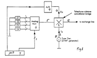
- Figure 1 shows an invention, including elements of a phone circuit used in describing the side tone balance bridge 1 to which the exchange line 2, the phone's transmitter line 3, the phone's receiver line 4, and a side tone network line 5 are connected.
- the multiplexer is controlled by the phone's microprocessor 7 to switch each of the networks Z1 to Z4 in turn to the balance bridge during a sidetone test routine.
- a signal generator 8 is connected to the transmitter line 3 and, under control of the microprocessor 7, transmits test signals for use in measuring the side tone level of each of the networks Z1 to Z4.
- the generator 8 may be a special purpose generator producing a "white noise" signal over a substantial part of frequency range of the phone, or it may produce signals at one or more frequencies.
- the generator 8 is the phone's DTMF generator used to transmit dialled digits to the exchange.
- a measuring circuit 9 is connected to receiver line 4, and measures the side tone level produced by each of the networks Z1 to Z4 during a test.
- the measured results are stored in RAM associated with microprocessor 7 for comparison with a predetermined optimum value which may be stored in ROM.
- the test result may be compared between themselves, the network which produces the lowest level being selected.
- the microprocessor 7 may be programmed to perform the test once only on installation, each time a call is made, or on dialing of a predetermined code.
- the microprocessor's side tone test routine is initiated by a signal from the dialing circuit.
- the microprocessor 7 switches a first of the networks, e.g. Z1, into the circuit by sending a command to the switching circuit 6.
- the dialling circuit instructs the DTMF generator to send a signal comprising a combination of tones representing the digit dialled to the line.
- the measuring circuit measures the level of the resulting side tone signal and this is stored in RAM.
- the microprocessor then switches the second network Z2 into the circuit, having first switched Z1 out of the circuit, the second digit is transmitted, and the side tone level produced by the second network is measured and the result stored.
- This process is repeated for each digit dialled until all networks have been tested.
- the microprocessor compares the test results, either among themselves or with a predetermined level, and selects the network which provides the optimum result.
- test signals may be produced by a noise generator rather than by the DTMF generator.
- the processor 7 may be programmed to perform the test only when a predetermined number is dialled and a connection made at the exchange.
- the processor 7 then causes the signal generator to transmit its test signals while the phone is connected to an established link.
- the phone company may provide several test loads, to one of which the phone would be connected at the exchange when the predetermined number is dialled so that the test could be carried out under simulated call conditions.
- the received signal in this case the side tone RX, is applied to a current generator 21 which produces an output which is a function of RX.
- the current generator 21 produces a DC current via diode D1 to charge capacitor C.
- the current generator 21 may also include a weighing factor to compensate for the difference frequencies of the tone signals used in RX.
- the absolute accuracy of the A/D measurement is not important.
- the relative accuracy of the consecutive measurement is important to the operation of selecting a side tone network.
- the DTMF generator uses signals at specific frequencies for each digit so the line impedance for different digits may differ, possibly giving rise to some inaccuracy in the test.
- the use of a noise generator would avoid this problem.
- the values of the impedances Z1 to Z4 need to be carefully selected to avoid compromises with some line conditions .
- Line conditions include exchange impedance, line type, guage of wire, and length of line. Although there are a discrete set of exchange impedances and line types (600, 1200, 0.4mm, 0.64mm etc.). The length of line is continuously variable. The impedances Z1 to Z4 need to be selected to allow for the range of line conditions.
Landscapes
- Engineering & Computer Science (AREA)
- Signal Processing (AREA)
- Telephone Function (AREA)
- Monitoring And Testing Of Exchanges (AREA)
- Telephonic Communication Services (AREA)
- Cable Transmission Systems, Equalization Of Radio And Reduction Of Echo (AREA)
Applications Claiming Priority (3)
| Application Number | Priority Date | Filing Date | Title |
|---|---|---|---|
| AUPM6938/94 | 1994-07-20 | ||
| AUPM693894 | 1994-07-20 | ||
| AUPM693894 | 1994-07-20 |
Publications (2)
| Publication Number | Publication Date |
|---|---|
| EP0703693A1 true EP0703693A1 (de) | 1996-03-27 |
| EP0703693B1 EP0703693B1 (de) | 2005-03-02 |
Family
ID=3781471
Family Applications (1)
| Application Number | Title | Priority Date | Filing Date |
|---|---|---|---|
| EP95111419A Expired - Lifetime EP0703693B1 (de) | 1994-07-20 | 1995-07-20 | Vorrichtung für Telefoneigenecho |
Country Status (4)
| Country | Link |
|---|---|
| EP (1) | EP0703693B1 (de) |
| CN (1) | CN1071523C (de) |
| AT (1) | ATE290291T1 (de) |
| NZ (1) | NZ272558A (de) |
Family Cites Families (2)
| Publication number | Priority date | Publication date | Assignee | Title |
|---|---|---|---|---|
| JPS58157286A (ja) * | 1982-03-13 | 1983-09-19 | Toshiba Corp | ボタン電話装置における防側音回路 |
| JPH0245865B2 (ja) * | 1983-11-22 | 1990-10-12 | Nippon Denshin Denwa Kk | Bosokuonkairo |
-
1995
- 1995-07-12 NZ NZ272558A patent/NZ272558A/en unknown
- 1995-07-19 CN CN95108993A patent/CN1071523C/zh not_active Expired - Fee Related
- 1995-07-20 EP EP95111419A patent/EP0703693B1/de not_active Expired - Lifetime
- 1995-07-20 AT AT95111419T patent/ATE290291T1/de not_active IP Right Cessation
Non-Patent Citations (1)
| Title |
|---|
| PATENT ABSTRACTS OF JAPAN * |
Also Published As
| Publication number | Publication date |
|---|---|
| EP0703693B1 (de) | 2005-03-02 |
| NZ272558A (en) | 1997-02-24 |
| CN1120770A (zh) | 1996-04-17 |
| ATE290291T1 (de) | 2005-03-15 |
| CN1071523C (zh) | 2001-09-19 |
Similar Documents
| Publication | Publication Date | Title |
|---|---|---|
| HU182505B (en) | Circuit arrangement for setting an interface up between at least one subscriber channel and a digital circuit containing switching matrix | |
| US4864622A (en) | Voice recognizing telephone | |
| US5802169A (en) | System and method for transmission system automatic impedance matching | |
| US4924489A (en) | Customer line tester | |
| US5722087A (en) | Method for interpreting dialled digits of a dialling sequence transmitted by a dialling means to a radio transceiver | |
| US4253155A (en) | Self-compensating measurement system | |
| US5915227A (en) | Cordless telephone | |
| US5398282A (en) | Automatic sidetone selector | |
| EP0703693B1 (de) | Vorrichtung für Telefoneigenecho | |
| AU698549B2 (en) | Telephone side tone arrangement | |
| HK1014411A (en) | Telephone side tone arrangement | |
| CA2226942A1 (en) | Method for providing call-charge information as well as call-charge device, subscriber terminal and service unit | |
| EP0055977A1 (de) | Tragbares Instrument zum Messen der Dämpfung einer Fernsprechteilnehmerleitung | |
| US4839920A (en) | Method for determining telephone dial pulse parameters independently of subscriber line length | |
| CA1321252C (en) | Side-tone adjusting system and method for key telephone system establishing plural kinds of speaking paths | |
| US4035583A (en) | Method to apply and disconnect a 16 KHz signal to a telephone line without producing clicks | |
| JP2758139B2 (ja) | デジタルループ伝送システムの信号損失の自動調整用回路 | |
| CA1130899A (en) | Gain controller for a teleconferencing bridge | |
| JPS63178692A (ja) | ボタン電話装置 | |
| HUT59781A (en) | Low-consumption control circuit for coin-box telephon sets | |
| US4034162A (en) | Telephone receiver-off-hook detector | |
| EP0617534A1 (de) | DTMF oder dezimales Signalisierungsverfahren für ein Telefon | |
| JP2918891B2 (ja) | 帯域内信号装置 | |
| JP2765045B2 (ja) | 帯域内信号装置 | |
| JPS61144137A (ja) | ハイブリツド回路の調整方法および装置 |
Legal Events
| Date | Code | Title | Description |
|---|---|---|---|
| PUAI | Public reference made under article 153(3) epc to a published international application that has entered the european phase |
Free format text: ORIGINAL CODE: 0009012 |
|
| AK | Designated contracting states |
Kind code of ref document: A1 Designated state(s): AT BE GB IT |
|
| 17P | Request for examination filed |
Effective date: 19960611 |
|
| 17Q | First examination report despatched |
Effective date: 20020913 |
|
| GRAP | Despatch of communication of intention to grant a patent |
Free format text: ORIGINAL CODE: EPIDOSNIGR1 |
|
| GRAS | Grant fee paid |
Free format text: ORIGINAL CODE: EPIDOSNIGR3 |
|
| GRAA | (expected) grant |
Free format text: ORIGINAL CODE: 0009210 |
|
| RAP1 | Party data changed (applicant data changed or rights of an application transferred) |
Owner name: ALCATEL Owner name: ALCATEL AUSTRALIA LIMITED |
|
| AK | Designated contracting states |
Kind code of ref document: B1 Designated state(s): AT BE GB IT |
|
| PG25 | Lapsed in a contracting state [announced via postgrant information from national office to epo] |
Ref country code: BE Free format text: LAPSE BECAUSE OF FAILURE TO SUBMIT A TRANSLATION OF THE DESCRIPTION OR TO PAY THE FEE WITHIN THE PRESCRIBED TIME-LIMIT Effective date: 20050302 Ref country code: AT Free format text: LAPSE BECAUSE OF FAILURE TO SUBMIT A TRANSLATION OF THE DESCRIPTION OR TO PAY THE FEE WITHIN THE PRESCRIBED TIME-LIMIT Effective date: 20050302 |
|
| REG | Reference to a national code |
Ref country code: GB Ref legal event code: FG4D |
|
| PLBE | No opposition filed within time limit |
Free format text: ORIGINAL CODE: 0009261 |
|
| STAA | Information on the status of an ep patent application or granted ep patent |
Free format text: STATUS: NO OPPOSITION FILED WITHIN TIME LIMIT |
|
| 26N | No opposition filed |
Effective date: 20051205 |
|
| REG | Reference to a national code |
Ref country code: HK Ref legal event code: WD Ref document number: 1014411 Country of ref document: HK |
|
| PGFP | Annual fee paid to national office [announced via postgrant information from national office to epo] |
Ref country code: GB Payment date: 20080722 Year of fee payment: 14 |
|
| PGFP | Annual fee paid to national office [announced via postgrant information from national office to epo] |
Ref country code: IT Payment date: 20090618 Year of fee payment: 15 |
|
| GBPC | Gb: european patent ceased through non-payment of renewal fee |
Effective date: 20090720 |
|
| PG25 | Lapsed in a contracting state [announced via postgrant information from national office to epo] |
Ref country code: GB Free format text: LAPSE BECAUSE OF NON-PAYMENT OF DUE FEES Effective date: 20090720 |
|
| PG25 | Lapsed in a contracting state [announced via postgrant information from national office to epo] |
Ref country code: IT Free format text: LAPSE BECAUSE OF NON-PAYMENT OF DUE FEES Effective date: 20100720 |