EP0703704A2 - MPEG2-verarbeitendes Steuergerät für halbpixel Bewegungskompensation - Google Patents
MPEG2-verarbeitendes Steuergerät für halbpixel Bewegungskompensation Download PDFInfo
- Publication number
- EP0703704A2 EP0703704A2 EP95306613A EP95306613A EP0703704A2 EP 0703704 A2 EP0703704 A2 EP 0703704A2 EP 95306613 A EP95306613 A EP 95306613A EP 95306613 A EP95306613 A EP 95306613A EP 0703704 A2 EP0703704 A2 EP 0703704A2
- Authority
- EP
- European Patent Office
- Prior art keywords
- output
- luminance
- color
- latch
- pixel
- Prior art date
- Legal status (The legal status is an assumption and is not a legal conclusion. Google has not performed a legal analysis and makes no representation as to the accuracy of the status listed.)
- Granted
Links
Images



Classifications
-
- H—ELECTRICITY
- H04—ELECTRIC COMMUNICATION TECHNIQUE
- H04N—PICTORIAL COMMUNICATION, e.g. TELEVISION
- H04N11/00—Colour television systems
- H04N11/04—Colour television systems using pulse code modulation
- H04N11/042—Codec means
- H04N11/044—Codec means involving transform coding
-
- H—ELECTRICITY
- H04—ELECTRIC COMMUNICATION TECHNIQUE
- H04N—PICTORIAL COMMUNICATION, e.g. TELEVISION
- H04N19/00—Methods or arrangements for coding, decoding, compressing or decompressing digital video signals
- H04N19/50—Methods or arrangements for coding, decoding, compressing or decompressing digital video signals using predictive coding
- H04N19/503—Methods or arrangements for coding, decoding, compressing or decompressing digital video signals using predictive coding involving temporal prediction
- H04N19/51—Motion estimation or motion compensation
-
- H—ELECTRICITY
- H04—ELECTRIC COMMUNICATION TECHNIQUE
- H04N—PICTORIAL COMMUNICATION, e.g. TELEVISION
- H04N19/00—Methods or arrangements for coding, decoding, compressing or decompressing digital video signals
- H04N19/10—Methods or arrangements for coding, decoding, compressing or decompressing digital video signals using adaptive coding
- H04N19/169—Methods or arrangements for coding, decoding, compressing or decompressing digital video signals using adaptive coding characterised by the coding unit, i.e. the structural portion or semantic portion of the video signal being the object or the subject of the adaptive coding
- H04N19/186—Methods or arrangements for coding, decoding, compressing or decompressing digital video signals using adaptive coding characterised by the coding unit, i.e. the structural portion or semantic portion of the video signal being the object or the subject of the adaptive coding the unit being a colour or a chrominance component
-
- H—ELECTRICITY
- H04—ELECTRIC COMMUNICATION TECHNIQUE
- H04N—PICTORIAL COMMUNICATION, e.g. TELEVISION
- H04N19/00—Methods or arrangements for coding, decoding, compressing or decompressing digital video signals
- H04N19/50—Methods or arrangements for coding, decoding, compressing or decompressing digital video signals using predictive coding
- H04N19/503—Methods or arrangements for coding, decoding, compressing or decompressing digital video signals using predictive coding involving temporal prediction
- H04N19/51—Motion estimation or motion compensation
- H04N19/523—Motion estimation or motion compensation with sub-pixel accuracy
-
- H—ELECTRICITY
- H04—ELECTRIC COMMUNICATION TECHNIQUE
- H04N—PICTORIAL COMMUNICATION, e.g. TELEVISION
- H04N5/00—Details of television systems
- H04N5/14—Picture signal circuitry for video frequency region
- H04N5/144—Movement detection
- H04N5/145—Movement estimation
Definitions
- the present invention relates to a half-pixel motion compensation controller accepting MPEG2, which implements half-pixel motion compensation suggested according to the MPEG2 algorithm.
- a half-pixel motion compensation is carried out by interpolating a result of motion compensation in units of pixel.
- the half-pixel motion compensation is performed by obtaining the average of desired pixel values, using an auxiliary memory or delay in order to simultaneously select nearby values of video data.
- Fig. 1A shows horizontal interpolation.
- Fig. 1B illustrates vertical interpolation, and
- Fig. 1C horizontal and vertical interpolation.
- mark x represents an interpolation point.
- auxiliary memory When only the auxiliary memory is used, a memory of at least four times is required. This is unfavorable in cost or volume. For this reason, a half-pixel motion compensation is used using a delay, which must use a clock faster than the system clock.
- the processing block unit of motion compensation varies with a frame/field picture and motion coding type.
- a controller is required.
- Such hardware configuration has not been, however, disclosed.
- a half-pixel motion compensation controller accepting MPEG2, which implements a half-pixel motion compensator using a 4 phase division in units of macroblock and a clock faster than the system clock, and employs a FIFO controller controlling the compensator.
- a half-pixel motion compensation controller accepting MPEG2, comprising: a luminance pixel unit motion compensator for compensating for pixel unit motion of a luminance signal according to an input luminance motion vector; a luminance half-pixel unit motion compensator for compensating for half-pixel unit motion of the luminance signal from the output of the luminance pixel unit motion compensator according to luminance half-pixel information from the luminance motion vector; a color motion vector converter for obtaining the motion vector of a color signal from the luminance motion vector; a color pixel unit motion compensator for compensating for pixel unit motion of the color signal according to the color motion vector output from the color motion vector converter; a color half-pixel unit motion compensator for compensating for half-pixel unit motion of the color signal from the output of the color pixel unit motion compensator according to color half-pixel and luminance half-pixel information from the color motion vector output from the color motion vector converter; a luminance FIFO for buffering the output data of the luminance
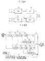
- a half-pixel motion compensation controller receiving MPEG2 embodying the invention comprises a luminance pixel unit motion compensator 10, luminance half-pixel unit motion compensator 20, color motion vector converter 30, color pixel unit motion compensator 40, color half-pixel unit motion compensator 50, luminance FIFO 60, color FIFO 70, luminance FIFO controller 80, and color FIFO controller 90.
- Luminance pixel unit motion compensator 10 compensates for pixel unit motion of a luminance signal according to an input luminance motion vector.
- Luminance half-pixel unit motion compensator 20 compensates for half-pixel unit motion of the luminance signal from the output of luminance pixel unit motion compensator 10 according to luminance half-pixel information from the luminance motion vector.
- Color motion vector converter 30 obtains the motion vector of a color signal from the luminance motion vector.
- Color pixel unit motion compensator 40 compensates for pixel unit motion of the color signal according to the color motion vector output from color motion vector converter 30.
- Color half-pixel unit motion compensator 50 compensates for half-pixel unit motion of the color signal from the output of color pixel unit motion compensator 40 according to color half-pixel and luminance half-pixel information from the color motion vector output from color motion vector converter 30.
- Luminance FIFO 60 buffers the output data of half-pixel unit motion compensator 20.
- Color FIFO 70 buffers the output data of color half-pixel unit motion compensator 50.
- Luminance FIFO controller 80 controls the input and output of luminance FIFO 60 according to sync signals and a frame/field picture and motion coding type selection signal output from the MPEG2 system.
- Color FIFO controller 90 controls the input and output of color FIFO 70 according to sync signals and a frame/field picture and motion coding type selection signal output from the MPEG2 system.
- Input video data is output as luminance video data displaced as much as a luminance motion vector LMV according to the vector input through luminance pixel unit motion compensator 10.
- the luminance video data output from luminance pixel unit motion compensator 10 is input to luminance half-pixel unit motion compensator 20 so that luminance half-pixel unit motion compensation is performed according to the luminance half-pixel information from luminance motion vector LMV.
- Color motion vector converter 30 obtains color motion vector CMV, that is, color pixel information, from luminance motion vector LMV. The thus obtained information is input to color pixel unit motion compensator 40.
- color pixel unit motion compensator 40 compensates for the pixel unit motion of the color data according to color motion vector CMV, and inputs the compensation result to color half-pixel unit motion compensator 50. Then, color half-pixel unit motion compensator 50 compensates for the color half-pixel unit motion according to the color half-pixel information from color motion vector CMV.
- the outputs of luminance and color half-pixel unit motion compensators 20 and 50 are input to luminance and color FIFOs 60 and 70, respectively, according to the control of luminance and color FIFO controllers 80 and 90.
- unnecessary data is inserted periodically into the output data of luminance half-pixel unit motion compensator 20.
- the unnecessarily inserted data is deleted by controlling a FIFO write enable signal produced from luminance FIFO controller 80.
- the output data of luminance half-pixel unit motion compensator 20 is written in luminance FIFO 60.
- fast-clock data is used starting from the pixel unit motion compensation. Therefore, fast clocks are also used in writing data in luminance FIFO 60.
- the write input of the half-pixel compensated luminance data must be interrupted to luminance FIFO 60 during the processing time for pixel unit motion compensation from the respective sync signals such as frame sync signal fsync, that is, the sync signal of motion compensation, as well as must unnecessary data be extracted.
- Color FIFO 70 is controlled by color FIFO controller 90, which operates similar to luminance FIFO controller 80. The detailed operation of luminance and color FIFOs 80 and 90 will be explained later.
- a generally processed macroblock if 16x16 pixels, can be formed in a single phase.
- parallel processing must be carried out.
- the method of forming a macroblock in a single phase can be employed in plurality as many as the division number.
- a macroblock to process is divided into four phases. In this state, the pixel unit motion and in turn half-pixel unit motion are compensated for. This method, no matter how a macroblock is divided, can be easily employed to the half-pixel motion compensation in case of using a delay.
- luminance half-pixel unit motion compensator 20 obtains half-pixel compensation data by interpolating nearby values according to luminance half-pixel information.
- the luminance half-pixel unit motion compensator is constructed as shown in Fig. 3, in which the luminance half-pixel unit motion compensator 20 is divided into four phases, that is, 0-3 phases of a macroblock.
- luminance half-pixel unit motion compensator 20 comprises a luminance half-pixel processing direction and delay controller 21 for outputting a luminance half-pixel processing direction control signal S1 and output delay control signal S2a and S2b for controlling the luminance half-pixel processing direction and output delay from luminance half-pixel information, 0-3 phase luminance half-pixel unit motion compensators 20a, 20b, 20c and 20d for making luminance half-pixel motion compensation data of the respective phases from their input data, and outputting luminance half-pixel motion compensation data of the respective phases according to luminance half-pixel processing direction control signal S1 and output delay control signals S2a and S2b from luminance half-pixel processing direction and delay controller 21, and a latch portion for latching the input data of the respective phases in parallel, and outputting them to the 0-3 phase luminance half-pixel unit motion compensators.
- the latch portion comprises a latch LA1 for latching the input data of phase 0 and outputting it to 0 phase luminance half-pixel unit motion compensator 20a, a latch LA2 for latching the input data of phase 1 and outputting it to 0 phase luminance half-pixel unit motion compensator 20a, a latch LA3 for latching the input data of phase 1 and outputting it to 3 phase luminance half-pixel unit motion compensator 20b, a latch LA4 for latching the input data of phase 2 and outputting it to 1 phase luminance half-pixel unit motion compensator 20b, a latch LA5 for latching the input data of phase 2 and outputting it to 2 phase luminance half-pixel unit motion compensator 20c, a latch LA6 for latching the input data of phase 3 and outputting it to 2 phase luminance half-pixel unit motion compensator 20c, a latch LA7 for latching the input data of phase 3 and outputting it to 3 phase luminance half-pixel unit motion compensator 20d, and a latch LA8 for latching the input data of phase 0
- O phase luminance half-pixel unit motion compensator 20a comprises a 5 delay portion 200 for delaying the input data of phase 0 by five pixels, a 4 delay portion 201 for delaying the output of 5 delay portion 200 by four pixels to obtain pixel unit luminance interpolation data, an adding portion 202 for arithmetically averaging the input data of phase 0 and the output of 5 delay portion 200 to obtain luminance interpolation data, 2 delay portion 203 for delaying the output of adding portion 202 by two pixels to output luminance vertical interpolation data, an adding portion 206 for arithmetically averaging the input data of phase 0 and phase 1 to obtain luminance interpolation data, 5 delay portion 207 for sequentially delaying the output of adding portion 206 by five pixels, 2 delay portion 209 for delaying the output of 5 delay portion 207 by two pixels to output luminance horizontal interpolation data, an adding portion 208 for arithmetically averaging the output of adding portion 206 and the output of 5 delay portion 207 to obtain luminance horizontal and vertical interpol
- adding portion 202 comprises an adder 220 for dividing the input data of phase 0 and the output of 5 delay portion 200 into the upper and lower bits, and summing the lower bits, a latch 222 for latching the output of adder 220, a latch 221 for dividing the input data of phase 0 and the output of 5 delay portion 200 into the upper and lower bits, and latching the upper bits, and an adder 223 for adding and outputting the outputs of adder 220 and latch 221.
- adding portion 206 comprises an adder 220 for dividing the input data of phase 0 and phase 1 into the upper and lower bits, and summing the lower bits, a latch 222 for latching the output of adder 220, a latch 221 for dividing the input data of phase 0 and phase 1 into the upper and lower bits, and latching the upper bits, and an adder 223 for adding and outputting the outputs of adder 220 and latch 221.
- adding portion 208 comprises an adder 220 for dividing the output of adding portion 206 and the output of 5 delay portion 207 into the upper and lower bits, and summing the lower bits, a latch 222 for latching the output of adder 220, a latch 221 for dividing the output of adding portion 206 and the output of 5 delay portion 207 into the upper and lower bits, and latching the upper bits, and an adder 223 for adding and outputting the outputs of adder 220 and latch 221.
- phase luminance half-pixel unit motion compensators 20b, 20c and 20d are constructed in the same manner as 0 phase luminance half-pixel unit motion compensator 20a.
- phase luminance half-pixel unit motion compensator 20b comprises a 5 delay portion 200 for delaying the input data of phase 1 by five pixels, a 4 delay portion 201 for delaying the output of 5 delay portion 200 by four pixels to obtain pixel unit luminance interpolation data, an adding portion 202 for arithmetically averaging the input data of phase 1 and the output of 5 delay portion 200 to obtain luminance interpolation data, 2 delay portion 203 for delaying the output of adding portion 202 by two pixels to output luminance vertical interpolation data, an adding portion 206 for arithmetically averaging the input data of phase 1 and phase 2 to obtain luminance interpolation data, 5 delay portion 207 for sequentially delaying the output of adding portion 206 by five pixels, 2 delay portion 209 for delaying the output of 5 delay portion 207 by two pixels to output luminance horizontal interpolation data, an adding portion 208 for arithmetically averaging the output of adding portion 206 and the output of 5 delay portion 207 to obtain luminance horizontal and vertical interpolation data,
- Adding portion 202 comprises an adder 220 for dividing the input data of phase 1 and the output of 5 delay portion 200 into the upper and lower bits, and summing the lower bits, a latch 222 for latching the output of adder 220, a latch 221 for dividing the input data of phase 1 and the output of 5 delay portion 200 into the upper and lower bits, and latching the upper bits, and an adder 223 for adding and outputting the outputs of adder 220 and latch 221.
- Adding portion 206 comprises an adder 220 for dividing the input data of phase 1 and phase 2 into the upper and lower bits, and summing the lower bits, a latch 222 for latching the output of adder 220, a latch 221 for dividing the input data of phase 1 and phase 2 into the upper and lower bits, and latching the upper bits, and an adder 223 for adding and outputting the outputs of adder 220 and latch 221.
- Adding portion 208 comprises an adder 220 for dividing the output of adding portion 206 and the output of 5 delay portion 207 into the upper and lower bits, and summing the lower bits, a latch 222 for latching the output of adder 220, a latch 221 for dividing the output of adding portion 206 and the output of 5 delay portion 207 into the upper and lower bits, and latching the upper bits, and an adder 223 for adding and outputting the outputs of adder 220 and latch 221.
- 2 phase luminance half-pixel unit motion compensator 20c is constructed in the same manner as 0-1 phase luminance half-pixel unit motion compensators 20a and 20b.
- 2 phase luminance half-pixel unit motion compensator 20c comprises a 5 delay portion 200 for delaying the input data of phase 2 by five pixels, a 4 delay portion 201 for delaying the output of 5 delay portion 200 by four pixels to obtain pixel unit luminance interpolation data, an adding portion 202 for arithmetically averaging the input data of phase 2 and the output of 5 delay portion 200 to obtain luminance interpolation data, 2 delay portion 203 for delaying the output of adding portion 202 by two pixels to output luminance vertical interpolation data, an adding portion 206 for arithmetically averaging the input data of phase 2 and phase 3 to obtain luminance interpolation data, 5 delay portion 207 for sequentially delaying the output of adding portion 206 by five pixels, 2 delay portion 209 for delaying the output of 5 delay portion 207 by two pixels to output luminance horizontal interpolation data, an adding portion 208 for arithmetically averaging the output of adding portion 206 and the output of 5 delay portion 207 to obtain luminance horizontal and vertical interpolation data,
- Adding portion 202 comprises an adder 220 for dividing the input data of phase 2 and the output of 5 delay portion 200 into the upper and lower bits, and summing the lower bits, a latch 222 for latching the output of adder 220, a latch 221 for dividing the input data of phase 2 and the output of 5 delay portion 200 into the upper and lower bits, and latching the upper bits, and an adder 223 for adding and outputting the outputs of adder 220 and latch 221.
- Adding portion 206 comprises an adder 220 for dividing the input data of phase 2 and phase 3 into the upper and lower bits, and summing the lower bits, a latch 222 for latching the output of adder 220, a latch 221 for dividing the input data of phase 1 and phase 2 into the upper and lower bits, and latching the upper bits, and an adder 223 for adding and outputting the outputs of adder 220 and latch 221.
- Adding portion 208 comprises an adder 220 for dividing the output of adding portion 206 and the output of 5 delay portion 207 into the upper and lower bits, and summing the lower bits, a latch 222 for latching the output of adder 220, a latch 221 for dividing the output of adding portion 206 and the output of 5 delay portion 207 into the upper and lower bits, and latching the upper bits, and an adder 223 for adding and outputting the outputs of adder 220 and latch 221.
- phase luminance half-pixel unit motion compensator 20d comprises a 5 delay portion 200 for delaying the input data of phase 3 by five and four pixels, a 4 delay portion 201 for delaying the output of 5 delay portion 200 by four pixels to obtain pixel unit luminance interpolation data, an adding portion 202 for arithmetically averaging the input data of phase 3 and the output of 5 delay portion 200 to obtain luminance interpolation data, 2 delay portion 203 for delaying the output of adding portion 202 by two pixels to output luminance vertical interpolation data, an adding portion 206 for arithmetically averaging the input data of phase 3 and phase 0 to obtain luminance interpolation data, 5 delay portion 207 for sequentially delaying the output of adding portion 206 by five pixels, 2 delay portion 209 for delaying the output of 5 delay portion 207 by two pixels to output luminance horizontal interpolation data, an adding portion 208 for arithmetically averaging the output of adding portion 206 and the output of 5 delay portion 207 to obtain luminance horizontal and vertical interpolation
- Adding portion 202 comprises an adder 220 for dividing the input data of phase 3 and the output of 5 delay portion 200 into the upper and lower bits, and summing the lower bits, a latch 222 for latching the output of adder 220, a latch 221 for dividing the input data of phase 3 and the output of 5 delay portion 200 into the upper and lower bits, and latching the upper bits, and an adder 223 for adding and outputting the outputs of adder 220 and latch 221.
- Adding portion 206 comprises an adder 220 for dividing the input data of phase 3 and phase 0 into the upper and lower bits, and summing the lower bits, a latch 222 for latching the output of adder 220, a latch 221 for dividing the input data of phase 3 and phase 0 into the upper and lower bits, and latching the upper bits, and an adder 223 for adding and outputting the outputs of adder 220 and latch 221.
- Adding portion 208 comprises an adder 220 for dividing the output of adding portion 206 and the output of 5 delay portion 207 into the upper and lower bits, and summing the lower bits, a latch 222 for latching the output of adder 220, a latch 221 for dividing the output of adding portion 206 and the output of 5 delay portion 207 into the upper and lower bits, and latching the upper bits, and an adder 223 for adding and outputting the outputs of adder 220 and latch 221.
- the operation of luminance half-pixel unit motion compensator 20 will be described below.
- Pixel unit luminance interpolation data YP and luminance vertical interpolation data YV are selected in multiplexer 204 according to processing direction control signal S1 from luminance half-pixel processing direction and delay controller 21, and luminance horizontal interpolation data YH and luminance horizontal/vertical interpolation data YHV in multiplexer 210. They are latched in latch portions 205 and 211.
- the outputs of multiplexers 204 and 210 are outputs to latch portions 205 and 211 according to output delay control signals S2a and S2b from luminance half-pixel processing direction and delay controller 21.
- one of pixel unit luminance interpolation data YP, vertical and horizontal luminance interpolation data YV and YH, and horizontal/vertical luminance interpolation data YHV is output as half-pixel motion compensation data for phase 0 through multiplexers 204 and 210 and latch portions 205 and 211 according to processing direction control signal S1 and output delay control signals S2a and S2b from luminance half-pixel processing direction and delay controller 21.
- output delay control signals S2a and S2b are delayed as long as delayed during multiplexing in order to perform synchronization.
- Adding portions 202, 206 and 208 perform interpolation with processing time 2D, and are usually used, as shown in Fig. 4. Adding portions 202, 206 and 208 have latches 222 and 221 in order to separate an eight-bit adder into four-bit adders, match speeds, divide the adder by two, and perform synchronization. The adding portions output the average of the two inputs, which is interpolation data.
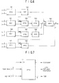
- color half-pixel unit motion compensator 50 comprises a pixel unit color interpolator 51 for delaying color pixel unit compensation data output from color pixel unit motion compensator 40, and outputting pixel unit color interpolation data, a color horizontal interpolator 52 for outputting color horizontal interpolation data using the color pixel unit compensation data delayed in pixel unit color interpolator 51, a color vertical interpolator 53 for outputting color vertical interpolation data using the color pixel unit compensation data delayed in color pixel unit motion compensator 40 and pixel unit color interpolator 51, a color horizontal and vertical interpolator 54 for outputting color horizontal and vertical interpolation data using data output from color vertical interpolator 53, a multiplexer 57 for selecting one of pixel unit color interpolation data output from pixel unit color interpolator 51, color horizontal interpolation data output from color horizontal interpolator 52, color vertical interpolation data output from color vertical interpolator 53, and color horizontal and vertical interpolation data output from color horizontal and vertical interpolator 54, and outputting
- pixel unit color interpolator 51 comprises a 9 delay portion 511 for delaying color pixel unit compensation data output from color pixel unit motion compensator 40 by nine pixels, and outputting the delayed data to color vertical interpolator 53, a 3 delay portion 512 for delaying the data output from 9 delay portion 511 by three pixels, and outputting the delayed data to color horizontal interpolator 52, a 1 delay portion 513 for delaying the data output from 3 delay portion 512 by one pixel, and outputting the delayed data to color horizontal interpolator 52, and a 4 delay portion 514 for delaying the data output from 1 delay portion 513 by four pixels to output pixel unit color interpolation data to multiplexer 57.
- Color horizontal interpolator 52 comprises an adding portion 521 for arithmetically averaging the color pixel unit compensation data delayed from 3 delay portion 512 and 1 delay portion 513 of pixel unit color interpolator 51, and a 1 delay portion 522 for delaying the data output from adding portion 521 by one pixel to output color horizontal interpolation data.
- adding portion 521 comprises an adder 581 for dividing the color pixel unit compensation data delayed from 3 delay portion 512 and 1 delay portion 513 of pixel unit color interpolator 51 in units of two bits, and summing the lowest two bits, a latch 582 for latching the output of adder 581 for synchronization and outputting two-bit data, a latch 583 for dividing the color pixel unit compensation data delayed from 3 delay portion 512 and 1 delay portion 513 of pixel unit color interpolator 51 in units of two bits, and latching the second lowest two bits for synchronization, an adder 584 for summing the output of latch 583 and the carry output from latch 582, a latch 585 for latching the output of adder 584 for synchronization to output two-bit data, a latch 586 for dividing the color pixel unit compensation data delayed from 3 delay portion 512 and 1 delay portion 513 of pixel unit color interpolator 51 in units of two bits, and latching the third lowest two bits for synchronization,
- Color vertical interpolator 53 comprises an adding portion 531 for arithmetically averaging the color pixel unit compensation data delayed from color pixel unit motion compensator 40 and pixel unit color interpolator 51, a 1 delay portion 532 for delaying the data output from adding portion 531 by one pixel to output it to color horizontal and vertical interpolator 54, a 1 delay portion 533 for delaying the data output from 1 delay portion 532 by one pixel to output it to color horizontal and vertical interpolator 54, and a 3 delay portion 534 for delaying the data output from 1 delay portion 533 by three pixels to output color vertical interpolation data to multiplexer 57.
- adding portion 531 is constructed in the same manner as that of color horizontal interpolator 52.
- Adding portion 531 comprises an adder 581 for dividing the color pixel unit compensation data delayed from color pixel unit motion compensator 40 and 9 delay portion 511 of pixel unit color interpolator 51 in units of two bits, and summing the lowest two bits, a latch 582 for latching the output of adder 581 for synchronization and outputting two-bit data, a latch 583 for dividing the color pixel unit compensation data delayed from color pixel unit motion compensator 40 and 9 delay portion 511 of pixel unit color interpolator 51 in units of two bits, and latching the second lowest two bits for synchronization, an adder 584 for summing the output of latch 583 and the carry output from latch 582, a latch 585 for latching the output of adder 584 for synchronization to output two-bit data, a latch 586 for dividing the color pixel unit compensation data delayed from color pixel unit motion compensator 40 and 9 delay portion
- Color horizontal and vertical interpolator 54 comprises an adder 541 for arithmetically averaging the data output from 1 delay portions 532 and 533 of color vertical interpolator 53, and outputting color horizontal and vertical interpolation data.
- adding portion 541 is constructed in the same manner as that of color horizontal interpolator 52.
- Adding portion 541 comprises an adder 581 for dividing the data delayed from 1 delay portions 532 and 533 of color vertical interpolator 53 in units of two bits, and summing the lowest two bits, a latch 582 for latching the output of adder 581 for synchronization and outputting two-bit data, a latch 583 for dividing the data delayed from 1 delay portions 532 and 533 of color vertical interpolator 53 in units of two bits, and latching the second lowest two bits for synchronization, an adder 584 for summing the output of latch 583 and the carry output from latch 582, a latch 585 for latching the output of adder 584 for synchronization to output two-bit data, a latch 586 for dividing the color pixel unit compensation data delayed from 1 delay portions 532 and 533 of color vertical interpolator 53 in units of two bits, and latching the third lowest two bits for synchronization, an adder 587 for summing the output of latch 586 and the carry output from latch 585, a latch 588 for latching
- adding portions 521, 531 and 541 each form an eight-bit adder with two-bit adders in order to match speeds in one clock. In the same way for luminance, the adding portions output average values.
- Color half-pixel unit motion compensator 50 has 17D for the overall processing time, and operates in the same principle as that of luminance half-pixel unit motion compensator 20.
- color motion vector converter 30 comprises an adding portion in which the highest bit of the luminance motion vector is input as carry, in case that it is negative, 1 is added to the input, and the lowest bit is truncated to obtain color motion vector CMV.
- the lowest bit is half-pixel motion information.
- color motion vector converter 30 including color half-pixel information converter 51 of Fig. 7 forms adding portion 31 consisting of three four-bit adders (not shown).
- adding portion 31 consisting of three four-bit adders (not shown).
- the highest bit of luminance motion vector LMV is coupled to carry input portion Cin of adding portion 31. In case that it is negative, 1 is added thereto.
- the lowest bit of the output data is truncated to obtain color motion vector CMV.
- the lowest bit of the remaining bits becomes half-pixel motion information/
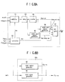
- luminance read signal generator 80b comprises a luminance write signal generator 80a for generating a write signal according to the respective sync signals and frame/field picture and motion coding type selection signal output from the MPEG2 system, and outputting the write signal to luminance FIFO 60, and a luminance read signal generator 80b for generating a read signal according to the respective sync signals and frame/field picture and motion coding type selection signal output from the MPEG2 system, and outputting the read signal to luminance FIFO 60.
- luminance write signal generator 80a comprises a selector 81 for selecting one of a macroblock mbclk and macroblock sync signal mbsync, a controller 82 for outputting a selection signal sel to selector 81 according to picture structure type signals pstr0 and pstrl and picture motion type signal pmtypel output from the MPEG2 system, a delay 83 for delaying the output of selector 81, a counter 84 for counting the output of delay 83 and generating a sawtooth-wave signal fifow-cnt for not writing unnecessary data, a write start signal generator 85 for generating a write start signal fifow-delay-win from the output of delay 83, a write completion signal generator 86 for generating write completion signal fifow-end-win from the output of counter 84, and an OR gate 87 for OR-operating the outputs of controller 82, counter 84, write signal start generator 85, and write completion signal generator
- luminance read signal generator 80b comprises a reset signal generator 88 for generating a reset signal fifo-rs in units of macroblocks according to a slice window signal swin output from the MPEG2 system, and outputting the result to luminance FIFO 60, and a read signal generator 89 for generating a read signal fifo-re according to slice window signal swin output from the MPEG2 system, and outputting the result to luminance FIFO 60.
- the operation of luminance FIFO controller 80 will be described with the timing diagrams of Fig. 9.
- Luminance FIFO controller 80 selects only a required part from data half-pixel-motion-compensated by the fast clock, inputs it to luminance FIFO 60 and outputs it in accordance with system clock mclk, finishing half-pixel motion compensation.
- selector 81 selects one of macroblock clock mbclk and macroblock sync signal mbsync according to selection signal Sel1.
- the thus selected signal is input to counter 84 and write start signal generator 85 through delay 83.
- Counter 84 generates sawtooth-wave signal fifow-cnt for not writing unnecessary data produced from 5x17 pixels by the interval of four pixels to luminance FIFO 60.
- Write start signal generator 85 generates write start signal fifow-delay-win, which calculates a delay time taken by data coming from frame sync signal fsync, a reference signal, to the input port of luminance FIFO 60, and inputs data to luminance FIFO 60 after the delay time.
- Write completion signal generator 86 generates write completion signal fifow-end-win from the output of counter 84. This signal disables the remaining processing time after processing by one macroblock period or half period according to picture structure type signals pstr0 and pstr1 and picture motion type signal pmtype1.
- Sawtooth-wave signal fifow-cnt and write start and completion signals fifow-delay-win and fifow-end-win are OR-operated with selection signal Sel2 for disabling the data input of luminance FIFO 60 while slice window signal swin indicative of a data active area, macroblock sync signal mbsync and macroblock clock mbclk are changed, in OR gate 87.
- the OR-operated result is generated as write signal fifo-we of luminance FIFO 60.
- Read signal generator 80b generates read signal fifo-re from read signal generator 89 using slice window signal swin.
- the read signal fifo-re makes data read after one macroblock so as not to allow luminance FIFO 60 to under-flow.
- Reset signal fifo-rs is generated from reset signal generator 88 for every macroblock.
- the fast system clock fmclk is latched by a, using macroblock sync signal mbsync, forming a fast macroblock sync signal fmbsync, which is used in writing or read.
- Color FIFO controller 90 consists of a color write signal generator and color read signal generator. Because the macroblock of the color signal is 8x8 pixels, color FIFO controller 90 is differentiated from luminance FIFO controller 80, with sawtooth-wave signal fifow-cnt for not writing unnecessary data, and with the different number of counters of counter 84. Other parts are the same as luminance FIFO controller 80.
- Color FIFO controller 90 comprises a write signal generator for generating a color write signal according to the respective sync signals and frame/field picture and motion coding type selection signal output from the MPEG2 system, and outputting the result to color FIFO 70, and a color read signal generator for generating a color read signal according to the respective sync signals and frame/field picture and motion coding type selection signal output from the MPEG2 system, and outputting the result to color FIFO 70.
- Counter 84 of luminance FIFO controller 80 generates sawtooth-wave signal fifow-cnt for not write unnecessary data produced from 5x17 pixels by the interval of four pixels to luminance FIFO 60.
- sawtooth-wave signal fifow-cnt of color FIFO controller 90 is 9x9 pixel unit in case of color so that it functions to input eight-pixel data and eliminate the ninth interpolation value. Except this respect, the operation of color FIFO controller 90 is the same as that of luminance FIFO controller 80.
- signal fifo-cnt-rs is to reset luminance and color FIFOs 60 and 70 in units of frame.
- Signal fifo-we-mb is a write signal for one macroblock.
- Reference numerals a1-a4 indicate four-pixel data for writing after delayed from macroblock sync signal mbsync.
- Reference numeral a5 is data not written. These operations are repeated eight times or sixteen times according to picture structure type signals pstr0 and pstr1, which are then disabled until the next macroblock.
- the present embodiment uses a 4 phase division in units of macroblock, a clock faster than the system clock, and a FIFO controller, implementing a half-pixel motion compensator accepting the MPEG2 algorithm.
Landscapes
- Engineering & Computer Science (AREA)
- Multimedia (AREA)
- Signal Processing (AREA)
- Color Television Systems (AREA)
- Processing Of Color Television Signals (AREA)
- Compression Or Coding Systems Of Tv Signals (AREA)
- Television Systems (AREA)
Applications Claiming Priority (2)
| Application Number | Priority Date | Filing Date | Title |
|---|---|---|---|
| KR2401494 | 1994-09-23 | ||
| KR1019940024014A KR0151210B1 (ko) | 1994-09-23 | 1994-09-23 | 엠펙2를 수용하는 반화소 움직임 보상조절장치 |
Publications (3)
| Publication Number | Publication Date |
|---|---|
| EP0703704A2 true EP0703704A2 (de) | 1996-03-27 |
| EP0703704A3 EP0703704A3 (de) | 1996-12-27 |
| EP0703704B1 EP0703704B1 (de) | 2003-07-02 |
Family
ID=19393347
Family Applications (1)
| Application Number | Title | Priority Date | Filing Date |
|---|---|---|---|
| EP95306613A Expired - Lifetime EP0703704B1 (de) | 1994-09-23 | 1995-09-20 | MPEG2-verarbeitendes Steuergerät für halbpixel Bewegungskompensation |
Country Status (5)
| Country | Link |
|---|---|
| US (1) | US5805227A (de) |
| EP (1) | EP0703704B1 (de) |
| KR (1) | KR0151210B1 (de) |
| CN (1) | CN1155224C (de) |
| DE (1) | DE69531181T2 (de) |
Cited By (3)
| Publication number | Priority date | Publication date | Assignee | Title |
|---|---|---|---|---|
| GB2309135A (en) * | 1996-01-11 | 1997-07-16 | Samsung Electronics Co Ltd | Estimating image motion by comparing adjacent image frame signals |
| EP0940774A3 (de) * | 1998-03-05 | 2000-07-05 | Matsushita Electric Industrial Co., Ltd. | Bewegungsvektorkodierungs- und Dekodierungsvorrichtung und Verfahren |
| WO2002096119A1 (en) * | 2001-05-25 | 2002-11-28 | Pace Soft Silicon Limited | Video data half-pel motion estimation |
Families Citing this family (13)
| Publication number | Priority date | Publication date | Assignee | Title |
|---|---|---|---|---|
| KR0166853B1 (ko) * | 1996-04-26 | 1999-03-20 | 문정환 | 디지탈 영상신호 처리용 메모리 시스템 |
| KR100442229B1 (ko) * | 1996-09-13 | 2004-10-08 | 엘지전자 주식회사 | 간이형hdtv비디오디코더및디코딩방법 |
| EP1056295B1 (de) * | 1998-12-10 | 2006-11-02 | Matsushita Electric Industrial Co., Ltd. | Arithmetische filtervorrichtung |
| US7266150B2 (en) * | 2001-07-11 | 2007-09-04 | Dolby Laboratories, Inc. | Interpolation of video compression frames |
| US7116831B2 (en) * | 2002-04-10 | 2006-10-03 | Microsoft Corporation | Chrominance motion vector rounding |
| CN101043628B (zh) * | 2002-09-06 | 2010-12-15 | 富士通株式会社 | 运动图像解码方法和运动图像解码装置 |
| JP3791922B2 (ja) * | 2002-09-06 | 2006-06-28 | 富士通株式会社 | 動画像復号化装置及び方法 |
| US7599438B2 (en) * | 2003-09-07 | 2009-10-06 | Microsoft Corporation | Motion vector block pattern coding and decoding |
| NO319629B1 (no) * | 2003-11-28 | 2005-09-05 | Tandberg Telecom As | Fremgangsmate for korrigering av interpolerte pikselverdier |
| CN101803362A (zh) * | 2007-09-10 | 2010-08-11 | Nxp股份有限公司 | 用于视频图像数据中的运动估计和运动补偿的方法和装置 |
| US9326004B2 (en) * | 2008-06-03 | 2016-04-26 | Broadcom Corporation | Reduced memory mode video decode |
| US8873637B2 (en) * | 2010-05-14 | 2014-10-28 | Qualcomm Incorporated | Hardware pixel processing pipeline and video processing instructions |
| US9667942B2 (en) * | 2012-11-20 | 2017-05-30 | Qualcomm Incorporated | Adaptive luminance compensation in three dimensional video coding |
Family Cites Families (13)
| Publication number | Priority date | Publication date | Assignee | Title |
|---|---|---|---|---|
| FR2649515B1 (fr) * | 1989-07-07 | 1991-09-20 | Thomson Csf | Dispositif de calcul d'une prediction pour un traitement d'images |
| SE465188B (sv) * | 1990-08-15 | 1991-08-05 | Televerket | Metod foer foerflyttning av bildpunkt med subpixelavstaand |
| JPH04354287A (ja) * | 1991-05-30 | 1992-12-08 | Sony Corp | 画像補間回路 |
| US5317397A (en) * | 1991-05-31 | 1994-05-31 | Kabushiki Kaisha Toshiba | Predictive coding using spatial-temporal filtering and plural motion vectors |
| JP2611591B2 (ja) * | 1991-10-31 | 1997-05-21 | 日本ビクター株式会社 | 動き補償装置 |
| JP2636622B2 (ja) * | 1992-03-13 | 1997-07-30 | 松下電器産業株式会社 | ビデオ信号の符号化方法及び復号化方法ならびにビデオ信号の符号化装置及び復号化装置 |
| US5461423A (en) * | 1992-05-29 | 1995-10-24 | Sony Corporation | Apparatus for generating a motion vector with half-pixel precision for use in compressing a digital motion picture signal |
| US5398079A (en) * | 1993-01-27 | 1995-03-14 | General Instrument Corporation | Half-pixel interpolation for a motion compensated digital video system |
| US5844616A (en) * | 1993-06-01 | 1998-12-01 | Thomson Multimedia S.A. | Method and apparatus for motion compensated interpolation |
| US5539467A (en) * | 1993-09-14 | 1996-07-23 | Goldstar Co., Ltd. | B-frame processing apparatus including a motion compensation apparatus in the unit of a half pixel for an image decoder |
| KR970003102B1 (ko) * | 1993-09-17 | 1997-03-14 | 대우전자 주식회사 | 영상 복호기에서의 하프 픽셀 움직임 보상 회로 |
| KR0126657B1 (ko) * | 1993-10-28 | 1997-12-29 | 구자홍 | 디지탈 영상 복원을 위한 움직임 보상장치 |
| US5650823A (en) * | 1995-03-27 | 1997-07-22 | International Business Machines Corporation | Half pel motion estimation method for B pictures |
-
1994
- 1994-09-23 KR KR1019940024014A patent/KR0151210B1/ko not_active Expired - Lifetime
-
1995
- 1995-09-20 EP EP95306613A patent/EP0703704B1/de not_active Expired - Lifetime
- 1995-09-20 DE DE69531181T patent/DE69531181T2/de not_active Expired - Fee Related
- 1995-09-21 US US08/531,678 patent/US5805227A/en not_active Expired - Lifetime
- 1995-09-22 CN CNB951172050A patent/CN1155224C/zh not_active Expired - Fee Related
Cited By (5)
| Publication number | Priority date | Publication date | Assignee | Title |
|---|---|---|---|---|
| GB2309135A (en) * | 1996-01-11 | 1997-07-16 | Samsung Electronics Co Ltd | Estimating image motion by comparing adjacent image frame signals |
| GB2309135B (en) * | 1996-01-11 | 1998-04-22 | Samsung Electronics Co Ltd | Method and apparatus for motion estimation |
| EP0940774A3 (de) * | 1998-03-05 | 2000-07-05 | Matsushita Electric Industrial Co., Ltd. | Bewegungsvektorkodierungs- und Dekodierungsvorrichtung und Verfahren |
| US6272179B1 (en) | 1998-03-05 | 2001-08-07 | Matsushita Electric Industrial Company, Limited | Image coding apparatus, image decoding apparatus, image coding method, image decoding method, and data storage medium |
| WO2002096119A1 (en) * | 2001-05-25 | 2002-11-28 | Pace Soft Silicon Limited | Video data half-pel motion estimation |
Also Published As
| Publication number | Publication date |
|---|---|
| KR960013093A (ko) | 1996-04-20 |
| CN1155224C (zh) | 2004-06-23 |
| EP0703704B1 (de) | 2003-07-02 |
| DE69531181T2 (de) | 2004-04-08 |
| US5805227A (en) | 1998-09-08 |
| DE69531181D1 (de) | 2003-08-07 |
| KR0151210B1 (ko) | 1998-10-15 |
| EP0703704A3 (de) | 1996-12-27 |
| CN1140958A (zh) | 1997-01-22 |
Similar Documents
| Publication | Publication Date | Title |
|---|---|---|
| EP0703704B1 (de) | MPEG2-verarbeitendes Steuergerät für halbpixel Bewegungskompensation | |
| US4383272A (en) | Video signal interpolation using motion estimation | |
| EP0613304B1 (de) | Halbpixelinterpolation für ein bewegungskompensiertes Digitalvideosystem | |
| EP0554586A2 (de) | Rekursiver Video Signal Prozessor | |
| EP0626788B1 (de) | Fernsehbilderdekodierarchitektur zur Ausführung eines 40 ms-Prozessalgorithmus in HDTV | |
| EP0474276A1 (de) | Video-Bewegungsvektorabschätzung mit asymmetrischem Aktualisierungsgebiet | |
| US4679084A (en) | Method and apparatus for freezing a television picture | |
| JPH04257183A (ja) | 画像信号処理方法及び装置 | |
| US6219102B1 (en) | Weighted median filter interpolator | |
| KR0140674B1 (ko) | 영상신호처리장치 및 처리방법 | |
| US5386248A (en) | Method and apparatus for reducing motion estimator hardware and data transmission capacity requirements in video systems | |
| US5307167A (en) | Digital zooming system utilizing image buffers and employing an approximated bilinear interpolation method | |
| US6762792B1 (en) | Digital still camera | |
| US5550591A (en) | Motion compensator for digital image restoration | |
| US4543607A (en) | Video processors | |
| US6985528B2 (en) | Apparatus and method for encoding and decoding moving picture using wavelet transformation and motion estimation | |
| EP0689358B1 (de) | Adressenerzeugungsschaltung für Bildbewegungskompensation | |
| EP0817478A1 (de) | Bilderinterpolationsverfahren zur Film-Modus Kompatibilität | |
| JP3132055B2 (ja) | 画像処理装置および画像処理方法 | |
| JP2637438B2 (ja) | 画像処理装置 | |
| GB2259422A (en) | Digital video signal processing | |
| JPS6243989A (ja) | 映像適応型走査線補間装置 | |
| JP3018384B2 (ja) | ビデオ信号処理回路 | |
| JP2650896B2 (ja) | 動き適応信号処理回路 | |
| KR950011044B1 (ko) | 고선명 텔레비젼 디코더 장치 |
Legal Events
| Date | Code | Title | Description |
|---|---|---|---|
| PUAI | Public reference made under article 153(3) epc to a published international application that has entered the european phase |
Free format text: ORIGINAL CODE: 0009012 |
|
| AK | Designated contracting states |
Kind code of ref document: A2 Designated state(s): DE FR GB NL |
|
| PUAL | Search report despatched |
Free format text: ORIGINAL CODE: 0009013 |
|
| AK | Designated contracting states |
Kind code of ref document: A3 Designated state(s): DE FR GB NL |
|
| 17P | Request for examination filed |
Effective date: 19970410 |
|
| 17Q | First examination report despatched |
Effective date: 20020524 |
|
| GRAH | Despatch of communication of intention to grant a patent |
Free format text: ORIGINAL CODE: EPIDOS IGRA |
|
| GRAH | Despatch of communication of intention to grant a patent |
Free format text: ORIGINAL CODE: EPIDOS IGRA |
|
| GRAA | (expected) grant |
Free format text: ORIGINAL CODE: 0009210 |
|
| AK | Designated contracting states |
Designated state(s): DE FR GB NL |
|
| REG | Reference to a national code |
Ref country code: GB Ref legal event code: FG4D |
|
| REF | Corresponds to: |
Ref document number: 69531181 Country of ref document: DE Date of ref document: 20030807 Kind code of ref document: P |
|
| ET | Fr: translation filed | ||
| PLBE | No opposition filed within time limit |
Free format text: ORIGINAL CODE: 0009261 |
|
| STAA | Information on the status of an ep patent application or granted ep patent |
Free format text: STATUS: NO OPPOSITION FILED WITHIN TIME LIMIT |
|
| 26N | No opposition filed |
Effective date: 20040405 |
|
| PGFP | Annual fee paid to national office [announced via postgrant information from national office to epo] |
Ref country code: DE Payment date: 20070913 Year of fee payment: 13 |
|
| PGFP | Annual fee paid to national office [announced via postgrant information from national office to epo] |
Ref country code: GB Payment date: 20070919 Year of fee payment: 13 |
|
| PGFP | Annual fee paid to national office [announced via postgrant information from national office to epo] |
Ref country code: NL Payment date: 20070903 Year of fee payment: 13 |
|
| PGFP | Annual fee paid to national office [announced via postgrant information from national office to epo] |
Ref country code: FR Payment date: 20070914 Year of fee payment: 13 |
|
| GBPC | Gb: european patent ceased through non-payment of renewal fee |
Effective date: 20080920 |
|
| PG25 | Lapsed in a contracting state [announced via postgrant information from national office to epo] |
Ref country code: NL Free format text: LAPSE BECAUSE OF NON-PAYMENT OF DUE FEES Effective date: 20090401 |
|
| NLV4 | Nl: lapsed or anulled due to non-payment of the annual fee |
Effective date: 20090401 |
|
| REG | Reference to a national code |
Ref country code: FR Ref legal event code: ST Effective date: 20090529 |
|
| PG25 | Lapsed in a contracting state [announced via postgrant information from national office to epo] |
Ref country code: DE Free format text: LAPSE BECAUSE OF NON-PAYMENT OF DUE FEES Effective date: 20090401 |
|
| PG25 | Lapsed in a contracting state [announced via postgrant information from national office to epo] |
Ref country code: FR Free format text: LAPSE BECAUSE OF NON-PAYMENT OF DUE FEES Effective date: 20080930 |
|
| PG25 | Lapsed in a contracting state [announced via postgrant information from national office to epo] |
Ref country code: GB Free format text: LAPSE BECAUSE OF NON-PAYMENT OF DUE FEES Effective date: 20080920 |