EP0703830B1 - Vorrichtung für die bohrloch-zyklonabscheidung - Google Patents
Vorrichtung für die bohrloch-zyklonabscheidung Download PDFInfo
- Publication number
- EP0703830B1 EP0703830B1 EP95915090A EP95915090A EP0703830B1 EP 0703830 B1 EP0703830 B1 EP 0703830B1 EP 95915090 A EP95915090 A EP 95915090A EP 95915090 A EP95915090 A EP 95915090A EP 0703830 B1 EP0703830 B1 EP 0703830B1
- Authority
- EP
- European Patent Office
- Prior art keywords
- outlet
- stream
- cyclone
- cyclone separator
- separator housing
- Prior art date
- Legal status (The legal status is an assumption and is not a legal conclusion. Google has not performed a legal analysis and makes no representation as to the accuracy of the status listed.)
- Expired - Lifetime
Links
Images



Classifications
-
- B—PERFORMING OPERATIONS; TRANSPORTING
- B01—PHYSICAL OR CHEMICAL PROCESSES OR APPARATUS IN GENERAL
- B01D—SEPARATION
- B01D17/00—Separation of liquids, not provided for elsewhere, e.g. by thermal diffusion
- B01D17/02—Separation of non-miscible liquids
- B01D17/0217—Separation of non-miscible liquids by centrifugal force
-
- B—PERFORMING OPERATIONS; TRANSPORTING
- B04—CENTRIFUGAL APPARATUS OR MACHINES FOR CARRYING-OUT PHYSICAL OR CHEMICAL PROCESSES
- B04C—APPARATUS USING FREE VORTEX FLOW, e.g. CYCLONES
- B04C5/00—Apparatus in which the axial direction of the vortex is reversed
- B04C5/24—Multiple arrangement thereof
- B04C5/28—Multiple arrangement thereof for parallel flow
-
- E—FIXED CONSTRUCTIONS
- E21—EARTH OR ROCK DRILLING; MINING
- E21B—EARTH OR ROCK DRILLING; OBTAINING OIL, GAS, WATER, SOLUBLE OR MELTABLE MATERIALS OR A SLURRY OF MINERALS FROM WELLS
- E21B43/00—Methods or apparatus for obtaining oil, gas, water, soluble or meltable materials or a slurry of minerals from wells
- E21B43/34—Arrangements for separating materials produced by the well
- E21B43/38—Arrangements for separating materials produced by the well in the well
- E21B43/385—Arrangements for separating materials produced by the well in the well by reinjecting the separated materials into an earth formation in the same well
Definitions
- the present invention relates to an apparatus for downhole cyclone separation and, in particular, an apparatus that can be used for oil/water separation in producing oil wells.
- United States Patent number 5,296,153 teaches a method of reducing the amount of formation water in oil recovered from an oil well through the insertion of a cyclone separator downhole in an oil well producing a stream of mixed oil and water.
- a first outlet of the cyclone separator is connected to a recovery conduit extending to surface.
- the recovery conduit conveys a recovery stream of oil with a reduced water content to surface.
- a second outlet of the cyclone separator is connected to a disposal conduit.
- the disposal conduit conveys a disposal stream of mainly water to a disposal site, which is usually a downhole formation chosen to be a disposal zone.
- the reference goes on to describe various pumping configurations which, when used in combination with the cyclone separator, can further enhance recovery.
- an apparatus for downhole cyclone separation including a multiple cyclone separator housing having an interior cavity, at least one mixed liquids inlet, at least one disposal stream outlet and at least one recovery stream outlet, a plurality of cyclone separators disposed in the interior cavity of the cyclone separator housing, each of the cyclone separators having: a separation chamber wherein liquids of differing densities are separated, at least one mixed liquids inlet through which liquids pass into the separation chamber, a first outlet for liquids of a first density range to pass from the separation chamber, a second outlet for liquids of a second density range to pass from the separation chamber, means for channelling a mixed liquids flow stream flowing through the at least one mixed liquids inlet of the multiple cyclone separator housing to the at least one mixed liquids inlet of each of the cyclone separators, means for channelling a recovery flow stream from the first outlet of each of the cyclone separators to the at least one recovery stream outlet of the multiple cycl
- the preferred method includes the following steps. Firstly, place a cyclone separator 12 downhole in an oil well 14 producing a mixed stream of oil, water and gas.
- Cyclone separator 12 includes a separation chamber 16 wherein liquids of differing densities are separated, a mixed liquids inlet 18 through which liquids pass into separation chamber 16, a first outlet 20 for liquids of a first density range to pass from separation chamber 16 and a second outlet 22 for liquids of a second density range to pass from separation chamber 16.
- first outlet 20 to a recovery conduit 24 extending to surface (not shown).
- second outlet 22 to a disposal conduit 26 extending to a selected disposal site (not shown).
- an enhanced pumping configuration in which a backpressure valve 30 is positioned on disposal conduit 26.
- the use of backpressure valve 30 ensures that there is sufficient pressure maintained to get the disposal stream into an underground disposal formation selected as a disposal site, while at the same time ensuring that the pump and cyclone separator are both operating within their most efficient operating ranges. It also enables a more accurate assessment to be made as to the amount of fluid being pumped into the disposal site.
- backpressure control means that can be used such as a flow restriction orifice.
- Backpressure valve 30 is preferred as it prevents a reversal of flow when pump 28 is turned off.
- Secondary pump 32 is positioned on the recovery conduit 24. Secondary pump 32 is intended to assist in conveying the recovery stream to the surface.
- the problem of gas breakout previously described, does not adversely affect the operation of secondary pump 32 due to the fact that pump 28 provides sufficient pressure to maintain the majority of the gas in solution.
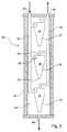
- Apparatus 40 includes a multiple cyclone separator housing 42 having an interior cavity 44, an mixed liquids inlet 46, a disposal stream outlet 48 and a recovery stream outlet 50. Although single inlets and outlets are illustrated, it will be appreciated that multiple inlets or outlets into housing 42 could be utilized depending upon the installation environment.
- a plurality of cyclone separators 12 are disposed in interior cavity 44 of multiple cyclone separator housing 42.
- each of cyclone separators 12 has a separation chamber 16 wherein liquids of differing densities are separated, a mixed liquids inlet 18 through which liquids pass into separation chamber 16, a first outlet 20 for liquids of a first density range to pass from separation chamber 16, and a second outlet 22 for liquids of a second density range to pass from separation chamber 16.
- Some means must be used for channelling the various flow streams flowing into mixed liquids inlet 18 and out of first outlet 20 and second outlet 22.
- the channelling means illustrated in FIGURE 3 is by way of conduits 52 and 54. It should be noted that only two conduit are required as in the illustrated embodiment interior cavity 44 of multiple cyclone separator housing 42 can serve as one of the channelling means.
- Conduit 52 has been connected as an inlet conduit allowing liquids to pass from mixed liquids inlet 46 in multiple cyclone separator housing 42 to mixed liquids inlets 18 of each of cyclone separators 12.
- Conduit 54 has been connected as an outlet conduit allowing liquids to pass from first outlet 20 of each of cyclone separators 12 to recovery stream outlet 50 of multiple cyclone separator housing 42.
- Second outlet 22 of each of cyclone separators 12 discharges directly into interior cavity 44, so that interior cavity 44 serves to connect second outlet 22 of each of cyclone separators 12 with disposal stream outlet 48.
- multiple cyclone separator housing 42 is placed downhole in an oil well producing a mixed stream of oil, water and gas.
- recovery stream outlet 50 of multiple cyclone separator housing 42 is connected to recovery conduit 24 extending to surface.
- disposal stream outlet 48 of multiple cyclone separator housing 42 is connected to disposal conduit 26 extending to a selected disposal site.
- a mixed stream of oil, water and gas is pumped by means of pump 28 into mixed liquids inlet 46 of multiple cyclone separator housing 42.
- the mixed stream of oil, water and gas is channelled by inlet conduit 50 to mixed liquid inlets 18 of each of cyclone separators 12, whereupon the oil and water is separated in separation chamber 16 of cyclone separators 12.
- a recovery stream of oil with a reduced water content passes through first outlet 20 of each of cyclone separators 12 for channelling by outlet conduit 54 to recovery stream outlet 50 in multiple cyclone separator housing 42 for conveyance through recovery conduit 24 to the surface.
- a disposal stream of water is discharged from second outlet 22 of each of cyclone separators 12 into interior cavity 44 for channelling to disposal stream outlet 48 of multiple cyclone separator housing 42 for disposal through disposal conduit 26 to the selected disposal site.
- apparatus 40 provides numerous advantages.
- the flow rate is increased.
- the pressure drop across each of separators 12 is reduced, which reduces the power requirements and reduces the chance of gas breakout downstream.
- Multiple cyclone separators 12 provide a redundancy, if any one cyclone separator ceases to function, the remaining cyclone separators can continue to function.
- a cyclone separator has a separation ratio that the percentage of the fluids flowing through first outlet 20 bears to the entire volume of fluids flowing through separation chamber 16. There is no minimum percentage. This means that in wells with an extremely high water content, the majority of the fluids (ie. the water) can be left downhole. There is however a maximum percentage of approximately 25 percent of the total volume leaving via first outlet 20. At this maximum percentage approximately 75 percent of the fluids are leaving via second outlet 22. This creates a problem with oil wells having a low water content. There is a danger that a portion of the oil can be pumped into the disposal zone along with the water.
- a plurality of apparatus 40 containing multiple cyclone separators can be connected in series. In this way a sequential reduction in the oil content can occur prior to pumping the disposal stream to the selected disposal site.
Landscapes
- Geology (AREA)
- Life Sciences & Earth Sciences (AREA)
- Engineering & Computer Science (AREA)
- Physics & Mathematics (AREA)
- Mining & Mineral Resources (AREA)
- Environmental & Geological Engineering (AREA)
- Fluid Mechanics (AREA)
- General Life Sciences & Earth Sciences (AREA)
- Geochemistry & Mineralogy (AREA)
- Thermal Sciences (AREA)
- Chemical & Material Sciences (AREA)
- Chemical Kinetics & Catalysis (AREA)
- Cyclones (AREA)
- Physical Water Treatments (AREA)
Claims (7)
- Vorrichtung zur Bohrloch-Zyklonabscheidung (40), mit einem Mehrfachzyklonabscheidergehäuse (42), das einen Innenraum (44), mindestens einen Flüssigkeitsgemischeinlaß (46), mindestens einen Entsorgungsstromauslaß (48) und mindestens einen Rückgewinnungsstromauslaß (50) hat, einer Vielzahl an Zyklonabscheidern (12), die in dem Innenraum (44) des Zyklonabscheidergehäuses (42) angeordnet sind, wobei jeder der Zyklonabscheider (12) folgendes hat: Eine Abscheidungskammer (16), in der Flüssigkeiten verschiedener Dichte getrennt werden, mindestens einen Flüssigkeitsgemischeinlaß (18), durch den Flüssigkeiten in die Abscheidungskammer (16) gehen, einen ersten Auslaß (20) für Flüssigkeiten eines ersten Dichtebereichs zum Verlassen der Abscheidungskammer (16), einen zweiten Auslaß (22) für Flüssigkeiten eines zweiten Dichtebereichs zum Verlassen der Abscheidungskammer (16), eine Einrichtung zum Leiten eines Flüssigkeitsgemischstromes (52), der durch den mindestens einen Flüssigkeitsgemischeinlaß (46) des Mehrfachzyklonabscheidergehäuses (42) strömt, zu dem mindestens einen Flüssigkeitsgemischeinlaß (18) eines jeden Zyklonabscheiders (12), eine Einrichtung zum Leiten eines Rückgewinnungsstromes (54) von dem ersten Auslaß (20) eines jeden Zyklonabscheiders (12) zu dem mindestens einen Rückgewinnungsstromauslaß (50) des Mehrfachzyklonabscheidergehäuses (42), eine Einrichtung zum Leiten eines Entsorgungsstromes (44) von dem zweiten Auslaß (22) eines jeden Zyklonabscheiders (12) zu dem mindestens einen Entsorgungsstromauslaß (48) des Mehrfachzyklonabscheidergehäuses (42), derart, daß gemischte Flüssigkeiten, die durch den mindestens einen Flüssigkeitsgemischeinlaß (46) des Mehrfachzyklonabscheidergehäuses (42) gehen, von der Einrichtung zum Leiten eines Stromes (52) zu dem mindestens einen Flüssigkeitsgemischeinlaß (18) eines jeden Zyklonabscheiders (12) geleitet werden, worauf die Flüssigkeiten in der Abscheidungskammer (16) der Zyklonabscheider (12) getrennt werden, wobei ein Rückgewinnungsstrom durch den ersten Auslaß (20) eines jeden Zyklonabscheiders (12) geht, um von der Einrichtung zum Leiten eines Stromes (54) zu dem mindestens einen Rückgewinnungsstromauslaß (50) in dem Mehrfachzyklonabscheidergehäuse (42) geleitet zu werden, und ein Entsorgungsstrom aus dem zweiten Auslaß (22) eines jeden Zyklonabscheiders (12) ausgestoßen wird, um von der Einrichtung zum Leiten eines Stromes (44) zu dem mindestens einen Entsorgungsstromauslaß (48) in dem Mehrfachzyklonabscheidergehäuse (42) geleitet zu werden, gekennzeichnet dadurch, daß:die Zyklonabscheider (12) vertikal angeordnet und vertikal fluchtend zueinander ausgerichtet und in einem Innenraum (44) des Mehrfachzyklonabscheidergehäuses (42) angeordnet sind;mindestens der mindestens eine Flüssigkeitsgemischauslaß (48) oder der erste Auslaß (20) oder der zweite Auslaß (22) eines jeden Zyklonabscheiders (12) vertikal angeordnet ist;der Innenraum (44) des Mehrfachzyklonabscheidergehäuses (42) als Einrichtung zum Leiten des Flüssigkeitsgemischstromes oder des Entsorgungsstromes oder des Rückgewinnungsstromes relativ zu jedem der Zyklonabscheider (12) dient; undder mindestens eine Entsorgungsstromauslaß (48) und der mindestens eine Rückgewinnungsstromauslaß (50) an entgegengesetzten vertikalen Gehäuseenden des Mehrfachzyklonabscheidergehäuses (42) angeordnet sind.
- Vorrichtung zur Bohrloch-Zyklonabscheidung (40) nach Anspruch 1, bei der jede der Leiteinrichtungen zusammen insgesamt mindestens zwei Leitungen (52, 54) aufweisen, die sich zwischen zwei der folgenden Ein- und Ausläße erstrekken: dem mindestens einen Flüssigkeitsgemischeinlaß (46) des Mehrfachzyklonabscheidergehäuses (42) und dem mindestens einen Flüssigkeitsgemischeinlaß (18) eines jeden Zyklonabscheiders (12), dem ersten Auslaß (20) eines jeden Zyklonabscheiders (12) und dem mindestens einen Rückgewinnungsstromauslaß (50) des Mehrfachzyklonabscheidergehäuses (42) und dem zweiten Auslaß (22) eines jeden Zyklonabscheiders (12) und dem mindestens einen Entsorgungsstromauslaß (48) des Mehrfachzyklonabscheidergehäuses (42), wobei die Leitungen (52, 54) an dem Mehrfachzyklonabscheidergehäuse (42) befestigt sind.
- Vorrichtung nach Anspruch 1 oder 2, bei der der Innenraum (44) als Einrichtung zum Leiten des Entsorgungsstromes dient.
- Vorrichtung nach einem der Ansprüche 1 bis 3, bei der die Einlaßflüssigkeit eine Mischung aus Öl in Wasser mit gelöstem Gas aufweist.
- Vorrichtung nach einem der Ansprüche 1 bis 4, ferner gekennzeichnet durch eine Pumpe (28), die wirkmäßig geschaltet ist, um Flüssigkeiten in jeden Zykloneinlaß (18) zu pumpen.
- Vorrichtung nach Anspruch 5, bei der die Pumpe (28) so ausgewählt ist, daß sie einen genügenden Druck in dem Öl- und Wasserstrom erzeugt, der durch die Pumpe geht, um den größten Teil irgend eines gelösten Gases in Lösung zu halten, während der Strom durch die Pumpe und den Zyklonabscheider geht.
- Vorrichtung nach Anspruch 6, ferner gekennzeichnet durch eine Rückdrucksteuerung an jedem zweiten Auslaß.
Applications Claiming Priority (3)
| Application Number | Priority Date | Filing Date | Title |
|---|---|---|---|
| US08/226,987 US5456837A (en) | 1994-04-13 | 1994-04-13 | Multiple cyclone apparatus for downhole cyclone oil/water separation |
| US226987 | 1994-04-13 | ||
| PCT/CA1995/000204 WO1995028230A1 (en) | 1994-04-13 | 1995-04-10 | Apparatus for downhole cyclone separation |
Publications (2)
| Publication Number | Publication Date |
|---|---|
| EP0703830A1 EP0703830A1 (de) | 1996-04-03 |
| EP0703830B1 true EP0703830B1 (de) | 1999-12-15 |
Family
ID=22851286
Family Applications (1)
| Application Number | Title | Priority Date | Filing Date |
|---|---|---|---|
| EP95915090A Expired - Lifetime EP0703830B1 (de) | 1994-04-13 | 1995-04-10 | Vorrichtung für die bohrloch-zyklonabscheidung |
Country Status (6)
| Country | Link |
|---|---|
| US (2) | US5456837A (de) |
| EP (1) | EP0703830B1 (de) |
| AU (1) | AU691603B2 (de) |
| CA (1) | CA2146743C (de) |
| NO (2) | NO313039B1 (de) |
| WO (1) | WO1995028230A1 (de) |
Families Citing this family (65)
| Publication number | Priority date | Publication date | Assignee | Title |
|---|---|---|---|---|
| NO924896L (no) * | 1992-12-17 | 1994-06-20 | Read Process Engineering As | Nede-i-hullet prosess |
| NO933517L (no) * | 1993-10-01 | 1995-04-03 | Anil As | Fremgangsmåte ved utvinning av hydrokarboner i et underjordisk reservoar |
| US5996690A (en) * | 1995-06-06 | 1999-12-07 | Baker Hughes Incorporated | Apparatus for controlling and monitoring a downhole oil/water separator |
| GB9519339D0 (en) * | 1995-09-22 | 1995-11-22 | Vortoil Separation Systems Ltd | A method of separating production fluid from an oil well |
| EP0874694B1 (de) * | 1996-01-12 | 1999-09-08 | Baker Hughes Limited | Zyklonabscheideranordnung und verfahren |
| GB2308995B (en) * | 1996-01-12 | 1999-08-25 | Vortoil Separation Systems Ltd | Downhole separation apparatus |
| US6080312A (en) * | 1996-03-11 | 2000-06-27 | Baker Hughes Limited | Downhole cyclonic separator assembly |
| US6033567A (en) * | 1996-06-03 | 2000-03-07 | Camco International, Inc. | Downhole fluid separation system incorporating a drive-through separator and method for separating wellbore fluids |
| US5730871A (en) * | 1996-06-03 | 1998-03-24 | Camco International, Inc. | Downhole fluid separation system |
| GB9614675D0 (en) * | 1996-07-12 | 1996-09-04 | Baker Hughes Inc | Oil well production |
| CA2262911C (en) * | 1996-08-01 | 2007-10-23 | Camco International, Inc. | Method and apparatus for the downhole metering and control of fluids produced from wells |
| EP1445420A3 (de) * | 1996-09-27 | 2004-09-08 | Baker Hughes Limited | Öltrenn- und Pumpsysteme |
| US6082452A (en) * | 1996-09-27 | 2000-07-04 | Baker Hughes, Ltd. | Oil separation and pumping systems |
| US5693225A (en) * | 1996-10-02 | 1997-12-02 | Camco International Inc. | Downhole fluid separation system |
| US6068053A (en) * | 1996-11-07 | 2000-05-30 | Baker Hughes, Ltd. | Fluid separation and reinjection systems |
| US5961841A (en) * | 1996-12-19 | 1999-10-05 | Camco International Inc. | Downhole fluid separation system |
| AU6324698A (en) | 1997-02-13 | 1998-09-08 | Baker Hughes Incorporated | Apparatus and methods for downhole fluid separation and control of water production |
| AU7987298A (en) * | 1997-06-24 | 1999-01-04 | Baker Hughes Incorporated | Cyclonic separator assembly |
| GB9713960D0 (en) | 1997-07-03 | 1997-09-10 | Schlumberger Ltd | Separation of oil-well fluid mixtures |
| US6126416A (en) * | 1998-01-13 | 2000-10-03 | Camco International, Inc. | Adjustable shroud for a submergible pumping system and pumping system incorporating same |
| NO308426B1 (no) * | 1998-07-13 | 2000-09-11 | Read Group As | FremgangsmÕte og innretning for produsering av et oljereservoar |
| US6173774B1 (en) * | 1998-07-23 | 2001-01-16 | Baker Hughes Incorporated | Inter-tandem pump intake |
| CA2247838C (en) | 1998-09-25 | 2007-09-18 | Pancanadian Petroleum Limited | Downhole oil/water separation system with solids separation |
| US6367547B1 (en) | 1999-04-16 | 2002-04-09 | Halliburton Energy Services, Inc. | Downhole separator for use in a subterranean well and method |
| US6336504B1 (en) | 2000-03-03 | 2002-01-08 | Pancanadian Petroleum Limited | Downhole separation and injection of produced water in naturally flowing or gas-lifted hydrocarbon wells |
| US6336503B1 (en) | 2000-03-03 | 2002-01-08 | Pancanadian Petroleum Limited | Downhole separation of produced water in hydrocarbon wells, and simultaneous downhole injection of separated water and surface water |
| US6382316B1 (en) | 2000-05-03 | 2002-05-07 | Marathon Oil Company | Method and system for producing fluids in wells using simultaneous downhole separation and chemical injection |
| GB2362901B (en) * | 2000-06-03 | 2004-03-31 | Weir Pumps Ltd | Downhole gas compression |
| US6457531B1 (en) | 2000-06-09 | 2002-10-01 | Wood Group Esp, Inc. | Water separation system with encapsulated electric submersible pumping device |
| US6457522B1 (en) | 2000-06-14 | 2002-10-01 | Wood Group Esp, Inc. | Clean water injection system |
| US6547003B1 (en) | 2000-06-14 | 2003-04-15 | Wood Group Esp, Inc. | Downhole rotary water separation system |
| US6502635B1 (en) | 2001-06-20 | 2003-01-07 | Chevron U.S.A. Inc. | Sub-sea membrane separation system with temperature control |
| RU2263821C2 (ru) * | 2001-08-15 | 2005-11-10 | Перельштейн Борис Хаимович | Способ работы погружного насоса |
| US20040188356A1 (en) * | 2003-03-24 | 2004-09-30 | Haydock Intellectual Properties, L.L.C. | System for producing large particle precipitates |
| US7000694B2 (en) * | 2003-06-04 | 2006-02-21 | Crews Gregory A | Oil anchor |
| US20050087336A1 (en) * | 2003-10-24 | 2005-04-28 | Surjaatmadja Jim B. | Orbital downhole separator |
| US7429332B2 (en) * | 2004-06-30 | 2008-09-30 | Halliburton Energy Services, Inc. | Separating constituents of a fluid mixture |
| US7370701B2 (en) * | 2004-06-30 | 2008-05-13 | Halliburton Energy Services, Inc. | Wellbore completion design to naturally separate water and solids from oil and gas |
| US7462274B2 (en) | 2004-07-01 | 2008-12-09 | Halliburton Energy Services, Inc. | Fluid separator with smart surface |
| US7823635B2 (en) * | 2004-08-23 | 2010-11-02 | Halliburton Energy Services, Inc. | Downhole oil and water separator and method |
| US7462225B1 (en) | 2004-09-15 | 2008-12-09 | Wood Group Esp, Inc. | Gas separator agitator assembly |
| US7461692B1 (en) | 2005-12-15 | 2008-12-09 | Wood Group Esp, Inc. | Multi-stage gas separator |
| US8291979B2 (en) * | 2007-03-27 | 2012-10-23 | Schlumberger Technology Corporation | Controlling flows in a well |
| US8715512B2 (en) * | 2007-04-03 | 2014-05-06 | Siemens Energy, Inc. | Systems and methods for liquid separation |
| US7814976B2 (en) * | 2007-08-30 | 2010-10-19 | Schlumberger Technology Corporation | Flow control device and method for a downhole oil-water separator |
| US8006757B2 (en) * | 2007-08-30 | 2011-08-30 | Schlumberger Technology Corporation | Flow control system and method for downhole oil-water processing |
| US7798217B2 (en) * | 2008-09-15 | 2010-09-21 | Darrell Lantz | Apparatus for separating a mixture of liquids of differing specific gravities in a wellbore |
| CN101793138B (zh) * | 2010-03-10 | 2013-06-26 | 大庆油田有限责任公司 | 水力旋流器与螺杆泵配合的井下油水分离方法 |
| GB2490346A (en) * | 2011-04-27 | 2012-10-31 | Dps Bristol Holdings Ltd | Cyclonic separator having a tapered core element |
| CN103362490A (zh) * | 2012-04-01 | 2013-10-23 | 北京化工大学 | 用于井下油-水分离的采注装置 |
| US9724707B2 (en) * | 2012-12-21 | 2017-08-08 | National Oilwell Varco, L.P. | Fluid treatment system, a fluid processing apparatus and a method of treating a mixture |
| CN103835694B (zh) * | 2014-03-27 | 2017-02-15 | 中国石油大学(华东) | 旋流器并联式海上用大流量井下油水分离器 |
| US10077646B2 (en) | 2015-07-23 | 2018-09-18 | General Electric Company | Closed loop hydrocarbon extraction system and a method for operating the same |
| US10323494B2 (en) | 2015-07-23 | 2019-06-18 | General Electric Company | Hydrocarbon production system and an associated method thereof |
| US10047596B2 (en) | 2015-07-23 | 2018-08-14 | General Electric Company | System and method for disposal of water produced from a plurality of wells of a well-pad |
| CN107882547B (zh) * | 2016-09-29 | 2023-08-04 | 中国石油化工股份有限公司 | 管道式高含水油井产液三相计量装置与方法 |
| US11098570B2 (en) | 2017-03-31 | 2021-08-24 | Baker Hughes Oilfield Operations, Llc | System and method for a centrifugal downhole oil-water separator |
| US10655446B2 (en) * | 2017-07-27 | 2020-05-19 | Saudi Arabian Oil Company | Systems, apparatuses, and methods for downhole water separation |
| EP3894517B1 (de) | 2018-12-12 | 2026-05-06 | C.C. Jensen A/S | System zur entfernung von wasser aus öl |
| US11173424B2 (en) * | 2019-03-08 | 2021-11-16 | Kbk Industries, Llc | Sand removal tank |
| CN111206913A (zh) * | 2020-03-13 | 2020-05-29 | 中国科学院力学研究所 | 一种井下双涡型旋流油水分离器 |
| CN112588461A (zh) * | 2020-11-26 | 2021-04-02 | 东北石油大学 | 一种用于油水分离的多级丛式旋流分离装置 |
| CA3150326A1 (en) * | 2021-03-01 | 2022-09-01 | Kevin Shackle | Ultraviolet radiation air sanitizing machine |
| US20250101846A1 (en) * | 2023-09-25 | 2025-03-27 | Halliburton Energy Services, Inc. | Downhole fluid and solid separation with sediment and nonproduction fluid management in a well |
| CN119549300B (zh) * | 2025-01-26 | 2025-03-28 | 东北石油大学三亚海洋油气研究院 | 适用于海上油田同井注采井下旋流分离器多级并联装置 |
Family Cites Families (57)
| Publication number | Priority date | Publication date | Assignee | Title |
|---|---|---|---|---|
| US3195468A (en) * | 1965-07-20 | Submersible pump | ||
| US2311963A (en) * | 1939-07-11 | 1943-02-23 | Union Oil Co | Gas anchor |
| US2398338A (en) * | 1942-10-16 | 1946-04-09 | Guy O Marchant | Combination heater and water knockout apparatus for treating oil well streams |
| US2726606A (en) * | 1951-07-16 | 1955-12-13 | Arthur P Davidson | Pumping system |
| US2872985A (en) * | 1956-12-26 | 1959-02-10 | Phillips Petroleum Co | Cyclone gas anchor |
| US2910002A (en) * | 1956-12-31 | 1959-10-27 | Phillips Petroleum Co | Two zone pumping |
| US3167019A (en) * | 1961-03-20 | 1965-01-26 | Dresser Ind | Dual zone pumping apparatus |
| BE756804A (fr) * | 1969-09-29 | 1971-03-01 | Wikdahl Nils Anders Lennart | Groupement de separateur a cyclone |
| US4241787A (en) * | 1979-07-06 | 1980-12-30 | Price Ernest H | Downhole separator for wells |
| US4296810A (en) * | 1980-08-01 | 1981-10-27 | Price Ernest H | Method of producing oil from a formation fluid containing both oil and water |
| US4464264A (en) * | 1982-03-04 | 1984-08-07 | Noel Carroll | Cyclone separator |
| FI850425A0 (fi) * | 1983-06-01 | 1985-02-01 | Noel Carroll | Anordning foer separering av vaetskor. |
| US4737287A (en) * | 1984-07-19 | 1988-04-12 | Noel Carroll | Fluid flow apparatus |
| GB2162445A (en) * | 1984-08-02 | 1986-02-05 | Derek Alan Colman | Cyclone separator |
| MX167588B (es) * | 1984-11-28 | 1993-03-31 | Conoco Specialty Prod | Aparato para procesar petroleo |
| GB2191425B (en) * | 1984-12-20 | 1989-06-21 | Noel Carroll | Apparatus for handling mixtures |
| US4617031A (en) * | 1985-02-26 | 1986-10-14 | Chevron Research Company | Hybrid double hydrocyclone-gravity gas/liquid separator |
| MX168627B (es) * | 1985-04-23 | 1993-06-02 | Conoco Specialty Prod | Sistema y aparato para la separacion de mezclas de multifasicas |
| US4976872A (en) * | 1986-02-28 | 1990-12-11 | Conoco Specialty Products Inc. | Cyclone separator |
| WO1987005234A1 (en) * | 1986-02-28 | 1987-09-11 | Carroll, Noel | Cyclone separator |
| JPH01502886A (ja) * | 1986-04-23 | 1989-10-05 | コノコ スペシャルティ プロダクツ インコーポレイティド | サイクロン セパレータ |
| GB2194572B (en) * | 1986-08-29 | 1989-12-20 | Elf Aquitaine | A device for separating and extracting components having different densities from an effluent |
| FR2603331B1 (fr) * | 1986-09-02 | 1988-11-10 | Elf Aquitaine | Dispositif de regulation du debit d'eau separee de son melange avec les hydrocarbures et reinjectee au fond du puits |
| FR2603330B1 (fr) * | 1986-09-02 | 1988-10-28 | Elf Aquitaine | Procede de pompage d'hydrocarbures a partir d'un melange de ces hydrocarbures avec une phase aqueuse et installation de mise en oeuvre du procede |
| US5009784A (en) * | 1986-10-03 | 1991-04-23 | Conoco Specialty Products Inc. | Cyclone separator with oppositely directed separating chambers |
| EP0332641B1 (de) * | 1986-11-21 | 1994-03-30 | Conoco Specialty Products Inc. | Zyklonabscheidevorrichtung |
| JPH02501045A (ja) * | 1986-11-26 | 1990-04-12 | デラウッド ピーティーワイ リミテッド | ハイドロサイクロン |
| CA1317237C (en) * | 1987-03-03 | 1993-05-04 | Martin Thomas Thew | Cyclone separator |
| GB8707306D0 (en) * | 1987-03-26 | 1987-04-29 | British Petroleum Co Plc | Underwater oilfield separator |
| US5021165A (en) * | 1987-06-10 | 1991-06-04 | Conoco Specialty Products | Oil and water separating system with hydrocyclone and floatation device |
| WO1988009698A1 (en) * | 1987-06-10 | 1988-12-15 | Conoco Specialty Products Inc. | Liquid separator |
| US4766957A (en) * | 1987-07-28 | 1988-08-30 | Mcintyre Jack W | Method and apparatus for removing excess water from subterranean wells |
| US5154826A (en) * | 1987-09-15 | 1992-10-13 | Delawood Pty. Ltd. | Hydrocyclone overflow transport |
| US4889475A (en) * | 1987-12-24 | 1989-12-26 | Tecumseh Products Company | Twin rotary compressor with suction accumulator |
| WO1989008503A1 (en) * | 1988-03-17 | 1989-09-21 | Conoco Specialty Products Inc. | Cyclone separator |
| DE3810951A1 (de) * | 1988-03-31 | 1989-10-12 | Klein Schanzlin & Becker Ag | Verfahren und vorrichtung zur energiegewinnung aus oelquellen |
| US4900445A (en) * | 1988-06-29 | 1990-02-13 | Conoco Inc. | Low pressure hydrocyclone separator |
| US4844817A (en) * | 1988-06-29 | 1989-07-04 | Conoco Inc. | Low pressure hydrocyclone separator |
| US4836935A (en) * | 1988-09-09 | 1989-06-06 | Conoco Inc. | Oil removal from waterflooding injection water |
| US4933094A (en) * | 1988-09-30 | 1990-06-12 | Conoco Specialty Products, Inc. | Method and apparatus for separating liquid components from a liquid mixture |
| US4911850A (en) * | 1988-09-30 | 1990-03-27 | Conoco Specialty Products, Inc. | Method and apparatus for separating liquid components from a liquid mixture |
| US4927536A (en) * | 1989-03-21 | 1990-05-22 | Amoco Corporation | Hydrocyclone separation system |
| US4964994A (en) * | 1989-03-21 | 1990-10-23 | Amoco Corporation | Hydrocyclone separator |
| FR2652610B1 (fr) * | 1989-09-29 | 1992-01-03 | Elf Aquitaine | Procede de pompage de melange liquide gaz dans un puits d'extraction petrolier et dispositif de mise en óoeuvre du procede. |
| US5172717A (en) * | 1989-12-27 | 1992-12-22 | Otis Engineering Corporation | Well control system |
| US5176164A (en) * | 1989-12-27 | 1993-01-05 | Otis Engineering Corporation | Flow control valve system |
| US4981175A (en) * | 1990-01-09 | 1991-01-01 | Conoco Inc | Recirculating gas separator for electric submersible pumps |
| US5071557A (en) * | 1990-08-30 | 1991-12-10 | Conoco Specialty Products Inc. | Liquid/liquid hydrocyclone |
| US5071556A (en) * | 1990-08-30 | 1991-12-10 | Conoco Specialty Products Inc. | Hydrocyclone having a high efficiency area to volume ratio |
| GB2248462A (en) * | 1990-10-04 | 1992-04-08 | Shell Int Research | Producing oil from a subsurface oil-containing formation layer |
| US5181837A (en) * | 1991-04-18 | 1993-01-26 | Vickers, Incorporated | Electric motor driven inline hydraulic apparatus |
| GB9123883D0 (en) * | 1991-11-11 | 1992-01-02 | Bhr Group Ltd | Hydrocyclone |
| NO924896L (no) * | 1992-12-17 | 1994-06-20 | Read Process Engineering As | Nede-i-hullet prosess |
| US5335732A (en) * | 1992-12-29 | 1994-08-09 | Mcintyre Jack W | Oil recovery combined with injection of produced water |
| US5296153A (en) * | 1993-02-03 | 1994-03-22 | Peachey Bruce R | Method and apparatus for reducing the amount of formation water in oil recovered from an oil well |
| CA2155131C (en) * | 1993-04-27 | 2001-06-12 | Jean S. Weingarten | Downhole gas-liquid separator for wells |
| NO933517L (no) * | 1993-10-01 | 1995-04-03 | Anil As | Fremgangsmåte ved utvinning av hydrokarboner i et underjordisk reservoar |
-
1994
- 1994-04-13 US US08/226,987 patent/US5456837A/en not_active Expired - Lifetime
-
1995
- 1995-04-10 EP EP95915090A patent/EP0703830B1/de not_active Expired - Lifetime
- 1995-04-10 AU AU22110/95A patent/AU691603B2/en not_active Ceased
- 1995-04-10 WO PCT/CA1995/000204 patent/WO1995028230A1/en not_active Ceased
- 1995-04-10 CA CA002146743A patent/CA2146743C/en not_active Expired - Lifetime
- 1995-12-12 NO NO19955038A patent/NO313039B1/no not_active IP Right Cessation
-
1996
- 1996-09-03 US US08/707,241 patent/US5830368A/en not_active Expired - Lifetime
-
2002
- 2002-01-30 NO NO20020490A patent/NO328369B1/no not_active IP Right Cessation
Also Published As
| Publication number | Publication date |
|---|---|
| NO20020490L (no) | 1996-02-12 |
| US5830368A (en) | 1998-11-03 |
| CA2146743C (en) | 2003-06-10 |
| AU691603B2 (en) | 1998-05-21 |
| EP0703830A1 (de) | 1996-04-03 |
| CA2146743A1 (en) | 1995-10-14 |
| NO313039B1 (no) | 2002-08-05 |
| WO1995028230A1 (en) | 1995-10-26 |
| NO20020490D0 (no) | 2002-01-30 |
| US5456837A (en) | 1995-10-10 |
| NO955038D0 (no) | 1995-12-12 |
| NO328369B1 (no) | 2010-02-01 |
| NO955038L (no) | 1996-02-12 |
| AU2211095A (en) | 1995-11-10 |
Similar Documents
| Publication | Publication Date | Title |
|---|---|---|
| EP0703830B1 (de) | Vorrichtung für die bohrloch-zyklonabscheidung | |
| EP0825896B1 (de) | Abscheidungssystem für die produktionsflüssigkeiten einer ölbohrung | |
| EP0537330B1 (de) | Hydrozyklontrennvorrichtung | |
| WO1998020233A3 (en) | Fluid separation and reinjection systems for oil wells | |
| US6189613B1 (en) | Downhole oil/water separation system with solids separation | |
| US6354318B2 (en) | System and method for handling multiphase flow | |
| US6080312A (en) | Downhole cyclonic separator assembly | |
| WO1998059153A1 (en) | Cyclonic separator assembly | |
| WO1998013579A3 (en) | Oil separation and pumping systems | |
| EP0874694B1 (de) | Zyklonabscheideranordnung und verfahren | |
| CA2231543A1 (en) | A method of separating production fluid from an oil well | |
| US3486297A (en) | Liquid and gas pumping unit | |
| US6173774B1 (en) | Inter-tandem pump intake | |
| US20030150731A1 (en) | Subsea production system | |
| EP0830494B1 (de) | Verfahren zum zykloneabscheiden im bohrloch | |
| RU2516093C1 (ru) | Станция перекачки и сепарации многофазной смеси | |
| CA2428056C (en) | Method of downhole cyclone oil/water separation and apparatus for the same | |
| CA2221191C (en) | Separator systems for well production fluids | |
| US6092603A (en) | Method and equipment for the flow of offshore oil production with primary gas separation | |
| EP1445420A3 (de) | Öltrenn- und Pumpsysteme | |
| GB2264147A (en) | Multi-phase pumping arrangement | |
| EP0910724B1 (de) | Bohrloch-zyklonabscheider |
Legal Events
| Date | Code | Title | Description |
|---|---|---|---|
| PUAI | Public reference made under article 153(3) epc to a published international application that has entered the european phase |
Free format text: ORIGINAL CODE: 0009012 |
|
| AK | Designated contracting states |
Kind code of ref document: A1 Designated state(s): FR GB |
|
| 17P | Request for examination filed |
Effective date: 19960403 |
|
| 17Q | First examination report despatched |
Effective date: 19980430 |
|
| GRAG | Despatch of communication of intention to grant |
Free format text: ORIGINAL CODE: EPIDOS AGRA |
|
| GRAG | Despatch of communication of intention to grant |
Free format text: ORIGINAL CODE: EPIDOS AGRA |
|
| GRAH | Despatch of communication of intention to grant a patent |
Free format text: ORIGINAL CODE: EPIDOS IGRA |
|
| GRAH | Despatch of communication of intention to grant a patent |
Free format text: ORIGINAL CODE: EPIDOS IGRA |
|
| GRAA | (expected) grant |
Free format text: ORIGINAL CODE: 0009210 |
|
| AK | Designated contracting states |
Kind code of ref document: B1 Designated state(s): FR GB |
|
| ET | Fr: translation filed | ||
| PLBE | No opposition filed within time limit |
Free format text: ORIGINAL CODE: 0009261 |
|
| STAA | Information on the status of an ep patent application or granted ep patent |
Free format text: STATUS: NO OPPOSITION FILED WITHIN TIME LIMIT |
|
| 26N | No opposition filed | ||
| REG | Reference to a national code |
Ref country code: GB Ref legal event code: IF02 |
|
| PGFP | Annual fee paid to national office [announced via postgrant information from national office to epo] |
Ref country code: GB Payment date: 20040414 Year of fee payment: 10 |
|
| PGFP | Annual fee paid to national office [announced via postgrant information from national office to epo] |
Ref country code: FR Payment date: 20040427 Year of fee payment: 10 |
|
| PG25 | Lapsed in a contracting state [announced via postgrant information from national office to epo] |
Ref country code: GB Free format text: LAPSE BECAUSE OF NON-PAYMENT OF DUE FEES Effective date: 20050410 |
|
| GBPC | Gb: european patent ceased through non-payment of renewal fee |
Effective date: 20050410 |
|
| PG25 | Lapsed in a contracting state [announced via postgrant information from national office to epo] |
Ref country code: FR Free format text: LAPSE BECAUSE OF NON-PAYMENT OF DUE FEES Effective date: 20051230 |
|
| REG | Reference to a national code |
Ref country code: FR Ref legal event code: ST Effective date: 20051230 |