EP0703870B1 - Vorrichtung zum führen und bremsen eines fadens - Google Patents
Vorrichtung zum führen und bremsen eines fadens Download PDFInfo
- Publication number
- EP0703870B1 EP0703870B1 EP94920940A EP94920940A EP0703870B1 EP 0703870 B1 EP0703870 B1 EP 0703870B1 EP 94920940 A EP94920940 A EP 94920940A EP 94920940 A EP94920940 A EP 94920940A EP 0703870 B1 EP0703870 B1 EP 0703870B1
- Authority
- EP
- European Patent Office
- Prior art keywords
- thread
- brake
- clamping region
- guiding element
- guiding
- Prior art date
- Legal status (The legal status is an assumption and is not a legal conclusion. Google has not performed a legal analysis and makes no representation as to the accuracy of the status listed.)
- Expired - Lifetime
Links
- 238000007664 blowing Methods 0.000 claims description 15
- 230000000694 effects Effects 0.000 claims description 8
- 238000012216 screening Methods 0.000 claims 3
- 230000009471 action Effects 0.000 description 7
- 238000012545 processing Methods 0.000 description 3
- 230000008859 change Effects 0.000 description 2
- 238000013461 design Methods 0.000 description 2
- 230000002349 favourable effect Effects 0.000 description 2
- 238000004519 manufacturing process Methods 0.000 description 2
- 230000006978 adaptation Effects 0.000 description 1
- 230000004323 axial length Effects 0.000 description 1
- 230000008901 benefit Effects 0.000 description 1
- 239000000919 ceramic Substances 0.000 description 1
- 238000005516 engineering process Methods 0.000 description 1
- 238000003780 insertion Methods 0.000 description 1
- 230000037431 insertion Effects 0.000 description 1
- 238000009940 knitting Methods 0.000 description 1
- 239000000463 material Substances 0.000 description 1
- 238000000034 method Methods 0.000 description 1
- 230000008569 process Effects 0.000 description 1
- 238000012546 transfer Methods 0.000 description 1
- 238000009941 weaving Methods 0.000 description 1
Images


Classifications
-
- B—PERFORMING OPERATIONS; TRANSPORTING
- B65—CONVEYING; PACKING; STORING; HANDLING THIN OR FILAMENTARY MATERIAL
- B65H—HANDLING THIN OR FILAMENTARY MATERIAL, e.g. SHEETS, WEBS, CABLES
- B65H57/00—Guides for filamentary materials; Supports therefor
- B65H57/003—Arrangements for threading or unthreading the guide
-
- B—PERFORMING OPERATIONS; TRANSPORTING
- B65—CONVEYING; PACKING; STORING; HANDLING THIN OR FILAMENTARY MATERIAL
- B65H—HANDLING THIN OR FILAMENTARY MATERIAL, e.g. SHEETS, WEBS, CABLES
- B65H59/00—Adjusting or controlling tension in filamentary material, e.g. for preventing snarling; Applications of tension indicators
- B65H59/10—Adjusting or controlling tension in filamentary material, e.g. for preventing snarling; Applications of tension indicators by devices acting on running material and not associated with supply or take-up devices
- B65H59/20—Co-operating surfaces mounted for relative movement
- B65H59/22—Co-operating surfaces mounted for relative movement and arranged to apply pressure to material
-
- B—PERFORMING OPERATIONS; TRANSPORTING
- B65—CONVEYING; PACKING; STORING; HANDLING THIN OR FILAMENTARY MATERIAL
- B65H—HANDLING THIN OR FILAMENTARY MATERIAL, e.g. SHEETS, WEBS, CABLES
- B65H2701/00—Handled material; Storage means
- B65H2701/30—Handled filamentary material
- B65H2701/31—Textiles threads or artificial strands of filaments
Definitions
- the invention relates to a device of the type specified in the preamble of claim 1.
- a thread storage and delivery device known from EP-0 450 686 A1 is equipped with a pneumatic threading device which has a slotted tube which extends over a considerable part of the axial length of the storage drum.
- the tube serves for the thread transport of the thread blown forward by means of an air stream and runs outside over a bristle brake ring which rests with brake bristles on a pull-off edge of the storage drum.
- the bristle brake ring has an interruption in the circumference.
- the slot of the tube does not point to the circumferential interruption of the brake ring, but is offset by approximately 90 °, so that the thread is only pulled out laterally from the tube after threading, before it is first between and then under the Brake bristles.
- the tube runs perpendicular to the plane defined by the clamping area of the brake bristles.
- a disk brake known from DE-34 09 179 A1 is threaded in by hand, as is a multi-disk brake known from DE-34 46 567 C1.
- the invention has for its object to provide a device of the type mentioned, in which the threading of the thread into the thread brake can be carried out more easily and with simpler structural means.
- the thread to be threaded is deliberately moved out of the thread travel path with normal (braked) thread running and forced to bypass the clamping area.
- This has the advantage that the setting of the brake elements for threading need not be changed, and that no aids for adjusting the brake elements are necessary for threading.
- the pulling action in the thread is used to insert the thread transverse to its direction of travel by stretching into the clamping area. This is favorable because the transverse force of the thread contactlessly bypassing the braking elements under the pulling action is able to push the braking elements away from one another slightly, so that the thread is only introduced into the clamping area without any significant mechanical load when the free thread end has already reached the thread taker and the thread is also supported by this.
- the thread is therefore not left to itself when it is inserted into the clamping area.
- the detour of the thread which immediately circumvents the clamping area, is consciously accepted, only then to transfer the thread into the normal thread travel and the clamping area via the tensile action between the thread feeder and the thread taker.
- the threading is simple and with simple constructional means. The rate of incorrect threading is practically reduced to zero.
- the embodiment according to claim 2 with the curvature of the guide member, takes into account the least possible resistance of the thread to be threaded.
- the blunt corners in the course of the guide element do not interfere with the conveyance of the thread.
- the guide member is easy to manufacture and adapted to the structural conditions of the braking elements.
- the air flow reliably follows the guide member.
- the thread is taken along the guide member and expediently forced into the bend of the U or V, so that it cannot move sideways.
- a particularly useful embodiment is set out in claim 5. As soon as the thread has entered the guide member, it can no longer deviate laterally from its predetermined bypass route. Only when the pulling action stretching the thread occurs is the thread pulled out through the longitudinal slot and into the clamping area.
- a particularly useful embodiment is set out in claim 6.
- Disc brakes are frequently used thread brakes in thread processing systems.
- the guide element With the guide element, the problem of automatic threading, which was difficult to master up to now, is easily solved.
- the guide member extends almost half the circumference of the brake plate.
- the brake actuators cooperate with the constriction formed by their circumferences with the guide member, so that the air flow is guided uniformly and the thread is conveyed rapidly forward.
- the alternative embodiment according to claim 7 is a so-called multi-disc brake (leaf spring brake) with a brake disc and an abutment, such as a pin or pin or with two brake discs.
- the lead member leads the thread to be threaded past the clamping area, into which the thread is then pulled in slightly from the side.
- the thread guide element is used in normal thread running to correctly support the thread in order to keep it in the clamping area.
- the thread in the thread guide element has a starting point from which it reliably arrives along the guide member in the direction of the thread taker.
- the thread is supported and stretched between the thread taker and the thread guiding element so that it easily enters the clamping area.
- a further thread guide element is also provided on the outlet side in the thread brake, which supports the easy sliding of the thread into the clamping area when the thread is stretched under the pulling action.
- the blowing direction of the directional nozzle is aimed at the clamping area. There the air is deflected to the side so that the air flow and with it the thread to be threaded is diverted from the guide member and the clamping area.
- the inclined blow-out direction of the directional nozzle ensures that the thread reliably enters the guide member during threading and is guided by it in the predetermined path.
- the embodiment according to claim 11 is also particularly expedient because the ejector suction and blowing nozzle sucks in the thread coming from the thread feeder and pressures it into Further direction towards the leader.
- the embodiment according to claim 13 relates to a thread brake with a shielding surface, the task of which is to avoid tangling of the thread on the thread brake and to facilitate threading.
- the ejector suction and blowing nozzle can be easily integrated into the base of the shielding element.
- the thread that is brought to the shielding element and is to be threaded is sucked into the through-channel and then brought in the thread brake to the guide element, which guides it around the clamping area in the direction of the thread taker before it pulls the thread by pulling action and brings it into the clamping area.
- the embodiment according to claim 14 is structurally simple because the base body or the foot part is used to attach the guide member.
- the adjustability of the guide element enables adaptation to the respective operating conditions.
- a device V for guiding and braking an approximately linear yarn Y is integrated in a yarn processing system in a manner not shown in detail.
- the device V has a thread feeder G, from which the thread Y runs to a thread taker N, which exerts a tensile effect Z on the thread Y.
- Part of the device is a thread brake B, which is provided between the thread take-up device G and the thread take-up device N in the normal thread travel path 7 indicated by the broken line.
- the thread feeder G is, for example, a supply spool 1 from which thread Y is drawn off.
- the thread taker N can be a thread storage and delivery device or the insertion device of a weaving machine or another device (e.g. on a knitting machine) that consumes or delivers thread.
- the thread taker N is an inlet device 2 of a thread delivery and storage device which exerts the tensile effect Z on the thread Y.
- the thread brake B has a base body 3 with a flange 4, in which a thread guide element 5, for example a thread eyelet, is attached in the normal thread path 7.
- a thread guide element 5, for example a thread eyelet is attached in the normal thread path 7.
- two brake elements E are resiliently resilient to one another.
- It is a circular brake actuator 9, 10, which define an annular clamping area K, through which the thread Y passes in the normal thread travel 7 to be braked.
- the brake actuators 9, 10 are movably mounted on a pin 11 arranged on the base body 3. If necessary, a thread guide hook 12 is provided between the brake actuators 9, 10, in which the thread Y is suspended eccentrically to the axis of the brake actuators 9, 10.
- a guide member L is attached to the brake elements E without contact, like a bicycle fender, which is used for threading the thread Y into the thread brake B.
- a pneumatic threading device P is provided, which in the embodiment shown contains a directional nozzle 13 connected to a compressed air source 14.
- the directional nozzle 13 has a blow-out direction which runs approximately in the direction of the thread path 7 or obliquely thereto, so that an air flow F can be generated.
- the guide member L lies in the plane of the clamping area K and the normal thread path 7 and has an arcuate shape.
- the guide member L has a receiving end 18 near the thread guide element 5 and an outlet end 19, which lies behind the braking elements E in the thread running direction and faces the thread taker N.
- a guide channel 6, open to the clamping area K, for the air flow F and the thread Y is provided in the guide member L.
- the guide channel 6 has a U-shaped or V-shaped cross section.
- the upper brake actuator 9 is displaceable along a threaded pin 15 and is pressed against the brake actuator 10 in the clamping area by means of an adjustable stop 16 and a spring 17.
- the guide member L is shown with a transverse distance from the braking elements E.
- the width of the guide channel 6 corresponds approximately to the distance between the edges of the adjoining brake plates 9 and 10. However, it is conceivable to make the width of the guide channel 6 smaller or larger than the distance between the edges of the brake plates 9, 10. If necessary, the guide channel 6 extends laterally around the edges of the brake actuators 9, 10, at least in the area in which the guide member L in FIG. 1 runs close to the brake actuators 9, 10.
- the guide channel 6 can have a V or a channel cross section instead of a U-shaped cross section.
- the depth of the guide channel 6 can vary over the longitudinal extent of the guide member L, as can the inclination of the side walls of the guide channel 6 or the inner curvature of the guide channel 6. Furthermore, the guide member L can be widened close to the thread guide element 5 in order to take over the thread Y more easily .
- the open side of the guide channel 6 can be covered by one or two elastic lips or soft bristles, which the thread pushes away during stretching.
- the blow-out direction can also point approximately in the direction of the thread path 7.
- a second guide element L (FIG. 1, shown in broken lines) must be provided symmetrically.
- the air flow is divided at the brake actuators 9, 10, so that the thread Y is conveyed along one or the other guide element L.
- the thread guide hook 12 is formed on two sides so that the thread Y after threading reliably from the thread guide hook 12 between the brake actuators 9, 10 is performed.
- FIG. 3 shows an embodiment in which the thread brake B is equipped on the inlet side with a shielding surface 20 which is fastened to the flange 4 of the base body 3. Furthermore, a second flange 4 'is provided on the outlet side of the thread brake B, which contains a through opening 32 for the thread.
- the thread guide hook 12 is located between the bulges.
- the shielding surface 20, which is either flat or convexly curved on the inlet side, optionally contains a thread eyelet 21 and a longitudinal passage 22 in a foot part 26, with which the shielding surface 20 is fixed to the flange 4 in an opening 25.
- the flange 4 is inclined, as is the contact surface of the foot part 26.
- a clamping nut 24 clamps the foot part 26 against the flange 4.
- An ejector suction and blowing nozzle is incorporated in the foot part 26 as a directional nozzle 13, which is connected via a line 23 to the pressure source 14 and generates the air flow F in the direction of the guide member L and a suction flow on the inlet side. If only one guide element L is provided, then the air flow F is directed obliquely to the guide channel 6. If two symmetrically arranged guide members L are provided, as in FIG. 1, then the air flow F can also target the braking elements E in the center.
- the longitudinal passage 22 changes its angular position and thus the air flow F its If the direction could change undesirably, it is expedient if the directional nozzle 13 'is accommodated in the part of the head part 26 which faces the braking elements E and does not change its orientation when the foot part 26 is rotated. It would also be conceivable to provide a separate blowing and a suction nozzle in order to suck in the thread Y and to convey it into the guide channel.
- the thread brake B of the device V according to FIG. 4 corresponds approximately to the thread brake B of FIG. 3.
- the difference is that the shielding surface 20 is held on the flange 4 with its foot part 26 in a fixed position.
- the foot part 26 consists of two molded parts 26a, 26b which are inserted into one another and which form the directional nozzle 13 ', ie an ejector suction and blowing nozzle. This is connected via the connection 23 to the pressure source 14, not shown, and acts in the longitudinal passage 22 in order to generate a suction flow and the air flow F into the guide channel 6 of the guide member G on the side facing the thread transmitter G.
- the guide member G is, for example in one piece, connected to the part 26a of the foot part 26 and is similar to the fender of a bicycle, so that it comprises the brake actuators 9, 10 and with its outlet end 19 points towards the normal thread travel path 7.
- the thread brake B is attached to the thread taker N, for example in the case of an inlet nozzle or an inlet thread eyelet of a thread storage and delivery device 34.
- a deflection nose 33 is formed on the end of the longitudinal passage 22 facing the brake elements E. , and the outlet of the longitudinal passage 22 extends upwards.
- a cross pin made of wear-resistant material could also be provided, which, however, does not hinder the thread Y in the normal thread path 7.
- the normal one Thread path 7 runs approximately rectilinearly from the longitudinal passage 22 to the thread taker N.
- FIGS. 5 to 7 show a multi-disc thread brake B which can be used in the device according to FIGS. 1 to 3 instead of the disk brake.
- the thread brake B according to FIGS. 5 to 7 has the base body 3 with the flange 4 and the thread guide element 5.
- the braking elements E are two approximately rectangular brake disks 9 ', 10' which are held on supports 27 and form an inlet gap which tapers in the thread running direction up to the clamping region K.
- the two brake plates 9 ', 10' are pressed resiliently against one another and define the clamping area K lying perpendicular to the plane of FIG. 5 and perpendicular to the thread running direction.
- a stationary abutment 10 " for example a pin or a pin, could also be used , be provided.
- the guide member L begins in the vicinity of the thread guide element 5 and in this area may even reach between the brake plates 9 ', 10'. Following this, the guide member L runs with its guide channel 6 upwards over the brake disks 9 ', 10' and then with a final curvature downwards.
- the guide channel 6 according to FIG. 5 can have different radii of curvature 28 over the longitudinal extent of the guide member. It is also conceivable to assemble the guide member L from straight sections or to form it with straight sections, each of which adjoins via obtuse angles (indicated by the broken line at 29).
- the guide member L in the manner of a closed round or profile tube 30 is formed with a longitudinal slot 31, on the edge of which an elastic covering surface or bristles can be provided if necessary.
- the longitudinal slot 31 faces the clamping area K.
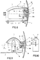
- the thread brake B shown in FIG. 8 essentially corresponds to the thread brake B of FIGS. 5 to 7.
- the arrangement of the shielding surface 20 on the flange 4 of the base body 3 is different, with the foot part 26 of the shielding surface 20 provided for fastening the shielding surface 20 being the directional nozzle 13 'in the form of an ejector suction and blowing nozzle, which acts in the longitudinal passage 22.
- a deflection nose 33 is formed, which deflects the air flow into the guide channel 6 of the guide member L.
- the guide member L engages over the rear ends of the two brake disks 9 ', 10' in the thread running direction.
- the upper corners of the two brake plates 9 ', 10' can be cut away in order to create a distance from the guide member and not to hinder the flight of the threaded thread.
- the embodiment of the thread brake B according to FIGS. 9 and 10 is a so-called "small" multi-disc brake, which is similar to a disk brake.
- a housing 36 fastened to the base body 3 two approximately rectangular and spring-loaded braking surfaces 9 ', 10' designed in the manner of brake disks are held with rounded edges, between which the thread is clamped in the normal thread travel path 7.
- the shielding surface 20 is fixed to the flange 4 with its foot part 26.
- the foot part 26 is in two parts and contains the directional nozzle 13 ', ie an ejector suction and blowing nozzle, which engages in the longitudinal passage 22.
- the guide member L is formed in one piece with the foot part 26 or with the one part of the foot part 26 that forms a deflection nose 33 and extends over the housing 36.
- Fig. 10 it is shown that the housing 36 forms an elbow-shaped inlet 40 to the braking surfaces 9 ', 10', which defines with the guide channel 6 at least over part of the longitudinal extent of the guide member L a flow-promoting and largely closed flow passage in which the Thread conveyed in the guide channel 6 is reliably displaced against the bottom of the guide channel 6. It would be conceivable to design the guide member L such that it is displaced in FIG. 10 into the gusset-shaped inlet gap 40 of the housing 36.
- the directional nozzle 13, 13 ' is activated for threading the thread Y.
- the thread end brought in any manner to the receiving end 18 of the guide member L or the free thread end sucked in by the suction effect of the ejector suction and blowing nozzle is conveyed into the guide channel 6.
- the air flow F then pushes the thread Y along the guide channel, bypassing the clamping area, until the free thread end is gripped by the thread taker N and a tensile effect is applied.
- the yarn Y which initially follows the detour 34, is stretched and transferred transversely to the normal yarn travel path 7 into the clamping area, wherein it is either lifted out of the open guide channel 6 or pulled through the longitudinal slot 31 (FIG. 7). As soon as the thread Y has properly returned to the normal thread path 7, the application of the directional nozzle 13, 13 'is ended.
Landscapes
- Looms (AREA)
- Spinning Or Twisting Of Yarns (AREA)
- Knitting Machines (AREA)
Abstract
Description
- Die Erfindung betrifft eine Vorrichtung der im Oberbegriff des Patentanspruchs 1 angegebenen Art.
- Bei einer aus WO 91-05728 bekannten Vorrichtung dieser Art wird dem in modernen fadenverarbeitenden Systemen fast unabdingbaren Problem der automatischen Einfädelung bereits Rechnung getragen, um teure und lange Stillstandszeiten für manuelles Einfädeln des Fadens in die Fadenbremse zu vermeiden. Es wird jedoch der vom Fadengeber kommende und durch die pneumatische Einfädelvorrichtung geförderte Faden auf dem Laufweg des normalen Fadenlaufs durch den Klemmbereich durchgefördert, wobei entweder ein Antrieb die Bremselemente in eine voneinander abgehobene Einfädelstellung verstellen oder der Luftstrom so kräftig ausgebildet sein muß, daß er die Bremselemente voneinander wegdrückt, um einen Durchgang für den Faden freizumachen. Bei diesem Prinzip sind aufwendige technische Mittel für die Verstellung der Bremselemente in die Einfädelstellung erforderlich. Der Fadennehmer nimmt am Einfädelvorgang nicht teil. Für Vorrichtungen mit einer Tellerbremse ist dieses Prinzip schwierig zu realisieren.
- Eine aus EP-0 450 686 Al bekannte Fadenspeicher- und -liefervorrichtung ist mit einer pneumatischen Einfädelvorrichtung ausgestattet, die ein sich über einen beträchtlichen Teil der axialen Länge der Speichertrommel erstreckendes, geschlitztes Rohr aufweist. Das Rohr dient zum Fadentransport des mittels eines Luftstromes vorwärts geblasenen Fadens und verläuft außen über einem Borsten-Bremsring, der mit Bremsborsten an einem Abzugsrand der Speichertrommel anliegt. Der Borstenbremsring weist eine Umfangsunterbrechung auf. Der Schlitz des Rohres weist nicht zur Umfangsunterbrechung des Bremsrings, sondern ist um ca. 90° dazu versetzt,-so daß der Faden nach dem Einfädeln erst seitlich aus dem Rohr herausgezogen wird, ehe er zunächst zwischen und danach unter die Bremsborsten gelangt. Das Rohr verläuft senkrecht zu der durch den Klemmbereich der Bremsborsten definierten Ebene.
- Eine aus DE-34 09 179 Al bekannte Tellerbremse wird von Hand eingefädelt, wie auch eine aus DE-34 46 567 C1 bekannten Lamellenbremse.
- Der Erfindung liegt die Aufgabe zugrunde, eine Vorrichtung der eingangs genannten Art zu schaffen, bei der das Einfädeln des Fadens in die Fadenbremse einfacher und mit einfacheren baulichen Mitteln durchführbar ist.
- Die gestellte Aufgabe wird erfindungsgemäß mit den Merkmalen des Patentanspruchs 1 gelöst.
- Bei dieser Ausbildung wird der einzufädelnde Faden bewußt aus dem Fadenlaufweg bei normalem (gebremstem) Fadenlauf herausbewegt und zur Umgehung des Klemmbereichs gezwungen. Dies hat den Vorteil, daß die Einstellung der Bremselemente für das Einfädeln nicht verändert zu werden braucht, und daß für das Einfädeln keine Hilfsmittel zum Verstellen der Bremselemente notwendig sind. Nachdem der Faden unter Umgehung des Klemmbereichs zum Fadennehmer gelangt ist, wird die Zugwirkung im Faden genutzt, um den Faden quer zu seiner Laufrichtung durch Strecken in den Klemmbereich einzuführen. Dies ist günstig, weil die unter der Zugwirkung entstehende Querkraft des die Bremselemente berührungslos umgehenden Fadens die Bremselemente leicht voneinander wegzudrücken vermag, so daß der Faden ohne nennenswerte mechanische Belastung erst dann in den Klemmbereich eingeführt wird, wenn das freie Fadenende schon den Fadennehmer erreicht hat und der Faden auch von diesem abgestützt ist. Der Faden bleibt somit beim Einführen in den Klemmbereich nicht sich selbst überlassen. Der den Klemmbereich zunächst umgehende Umweg des Fadens wird bewußt in Kauf genommen, um erst anschließend über die Zugwirkung zwischen dem Fadengeber und dem Fadennehmer den Faden in den normalen Fadenlaufweg und den Klemmbereich zu überführen. Das Einfädeln gestaltet sich einfach und mit einfachen baulichen Mitteln. Die Quote fehlerhafter Einfädelungen wird praktisch auf Null reduziert.
- Die Ausführungsform gemäß Anspruch 2 trägt mit dem Krümmungsverlauf des Leitglieds einer möglichst widerstandsarmen Förderung des einzufädelnden Fadens Rechnung.
- Bei der alternativen Ausführungform gemäß Anspruch 3 stören die stumpfen Ecken im Verlauf des Leitgliedes die Förderung des Fadens nicht. Das Leitglied ist einfach herstellbar und an die baulichen Verhältnisse der Bremselemente angepaßt.
- Bei der Ausführungsform gemäß Anspruch 4 folgt die Luftströmung zuverlässig dem Leitglied. Der Faden wird dem Leitglied entlang mitgenommen und zweckmäßigerweise in die Beuge des U oder V gezwungen, so daß er nicht seitlich auszuweichen vermag.
- Eine besonders zweckmäßige Ausführungsform geht aus Anspruch 5 hervor. Sobald der Faden in das Leitglied eingetreten ist, kann er seitlich nicht mehr von seinem vorbestimmten Umgehungsweg abweichen. Erst bei Auftreten der den Faden streckenden Zugwirkung wird der Faden durch den Längsschlitz heraus und in den Klemmbereich hineingezogen.
- Eine besonders zweckmäßige Ausführungsform geht aus Anspruch 6 hervor. Tellerbremsen sind häufig eingesetzte Fadenbremsen in fadenverarbeitenden Systemen. Mit dem Leitglied wird das bisher schwierig zu beherrschende Problem der automatischen Einfädelung einfach gelöst. Das Leitglied erstreckt sich fast über den halben Umfang der Bremsteller. Die Bremsteller kooperieren mit der von ihren Umfängen gebildeten Einschnürung mit dem Leitglied, so daß der Luftstrom gleichmäßig geführt und der Faden rasch vorwärts gefördert wird.
- Die alternative Ausführungsform gemäß Anspruch 7 ist eine sogenannte Lamellenbremse(Blattfederbremse) mit einer Bremslamelle und einem Widerlager, wie einem Zapfen oder Stift bzw. mit zwei Bremslamellen. Das Leitglied führt den einzufädelnden Faden am Klemmbereich vorbei, in den der Faden dann leicht von der Seite her hineingezogen wird.
- Bei der Ausbildung gemäß Anspruch 8 dient das Fadenführelement bei normalem Fadenlauf zum korrekten Abstützen des Fadens, um ihn im Klemmbereich zu halten. Beim Einfädeln hat der Faden im Fadenführelement einen Ausgangspunkt, von dem er zuverlässig entlang des Leitgliedes bis in Richtung zum Fadennehmer gelangt. Sobald seitens des Fadennehmers die Zugwirkung im Faden eintritt, wird der Faden zwischen dem Fadennehmer und dem Fadenführelement abgestützt und gestreckt, damit er leicht in den Klemmbereich eintritt. Gegebenenfalls ist aber auch ablaufseitig in der Fadenbremse ein weiteres Fadenführelement vorgesehen, das beim Strecken des Fadens unter der Zugwirkung das leichte Hineingleiten des Fadens in den Klemmbereich unterstützt.
- Bei der Ausführungsform gemäß Anspruch 9 zielt die Ausblaserichtung der Richtungsdüse auf den Klemmbereich. Dort wird die Luft so zur Seite abgelenkt, daß die Luftströmung und mit ihr der einzufädelnde Faden vom Leitglied und dem Klemmbereich umgeleitet wird.
- Bei der Ausführungsform gemäß Anspruch 10 ist durch die schräggestellte Ausblasrichtung der Richtungsdüse sichergestellt, daß der Faden beim Einfädeln zuverlässig in das Leitglied eintritt und von diesem in der vorbestimmten Bahn geführt wird.
- Besonders zweckmäßig ist ferner die Ausführungsform gemäß Anspruch 11, weil die Ejektor-Saug- und Blasdüse den vom Fadengeber kommenden Faden ansaugt und mit Druck in Richtung zum Leitglied weiterfördert. Es ist allerdings auch denkbar, die Düsenfunktionen zu trennen und getrennte Blas- und Saugdüsen vorzusehen, um den Faden in die Fadenbremse und dann durch diese hindurchzufördern.
- Eine baulich einfache und herstellungs- sowie montagetechnisch günstige Ausführungsform geht aus Anspruch 12 hervor.
- Die Ausführungsform gemäß Anspruch 13 bezieht sich auf eine Fadenbremse mit einer Abschirmfläche, deren Aufgabe es ist, ein Verwickeln des Fadens an der Fadenbremse zu vermeiden und das Einfädeln zu erleichtern. Die Ejektor-Saug- und Blasdüse läßt sich baulich einfach in den Fußteil des Abschirmelements integrieren. Der zum Abschirmelement gebrachte, einzufädelnde Faden wird in den Durchgangskanal gesaugt und dann in der Fadenbremse zum Leitglied gebracht, das ihn um den Klemmbereich herum in Richtung zum Fadennehmer leitet, ehe dieser durch Zugwirkung den Faden streckt und in den Klemmbereich bringt.
- Die Ausführungsform gemäß Anspruch 14 ist baulich einfach, weil der Grundkörper oder der Fußteil zum Befestigen des Leitglieds benutzt wird. Die Einstellbarkeit des Leitglieds ermöglicht die Anpassung an die jeweiligen Betriebsverhältnisse.
- Bei der Ausbildung gemäß Anspruch 15 ist von vornherein dafür gesorgt, daß der einzufädelnde Faden auf jeden Fall zum Fadennehmer gelangt, unabhängig davon, an welche Seite des Klemmbereichs er gefördert wird. Speziell bei einer Tellerbremse, deren runde Bremsteller die Luftströmung aufteilen, besteht nämlich die Möglichkeit, daß der Faden einmal zur einen und einmal zur anderen Seite des Klemmbereichs gefördert wird. Wenn zwei Leitglieder symmetrisch angeordnet sind, ist in jedem Falle ein korrektes Einfädeln sichergestellt.
- Anhand der Zeichnung werden Ausführungsformen des Erfindungsgegenstandes erläutert. Es zeigen:
- Fig. 1
- eine schematische Seitenansicht einer Vorrichtung zum Führen und Bremsen eines Fadens, wobei die Vorrichtung eine Tellerbremse enthält,
- Fig. 2
- einen Schnitt in der Ebene II-II von Fig. 1,
- Fig. 3
- eine Draufsicht einer anderen Ausführungsform,
- Fig. 4
- eine Seitenansicht einer weiteren Variante,
- Fig. 5
- eine Draufsicht auf eine Fadenbremse vom Typ einer Lamellenbremse,
- Fig. 6
- eine Seitenansicht zu Fig. 4,
- Fig. 7
- eine Schnittansicht in der Ebene VI-VI von Fig. 5,
- Fig. 8
- eine Seitenschnittansicht einer Variante,
- Fig. 9
- eine Seitenschnittansicht einer weiteren Ausführungsform, und
- Fig. 10
- eine Detailvariante aus Fig. 9 in Blickrichtung X.
- Eine Vorrichtung V zum Führen und Bremsen eines in etwa linear laufenden Fadens Y ist auf nicht detailliert gezeigte Weise in ein fadenverarbeitendes System integriert. Die Vorrichtung V weist einen Fadengeber G auf, von dem der Faden Y zu einem Fadennehmer N verläuft, der auf den Faden Y eine Zugwirkung Z ausübt. Teil der Vorrichtung ist eine Fadenbremse B, die zwischen dem Fadengeber G und dem Fadennehmer N im strichliert angedeuteten, normalen Fadenlaufweg 7 vorgesehen ist. Der Fadengeber G ist beispielsweise eine Vorratsspule 1, von der Faden Y abgezogen wird. Der Fadennehmer N kann ein Fadenspeicher- und -liefergerät oder die Eintragvorrichtung einer Webmaschine oder ein anderes Gerät (z.B. an einer Strickmaschine), das Faden verbraucht oder weiterliefert, sein. Beispielsweise ist der Fadennehmer N eine auf den Faden Y die Zugwirkung Z ausübende Einlaßvorrichtung 2 eines Fa- denliefer- und -speichergeräts.
- Die Fadenbremse B gemäß den Fig. 1 und 2 weist einen Grundkörper 3 mit einem Flansch 4 auf, in dem ein Fadenführelement 5, z.B. eine Fadenöse, im normalen Fadenlaufweg 7 angebracht ist. In der Fadenbremse B liegen zwei Bremselemente E federnd nachgiebig aneinander. Es handelt sich um kreisrunde Bremsteller 9, 10, die einen kreisringförmigen Klemmbereich K definieren, durch den der Faden Y im normalen Fadenlaufweg 7 durchläuft, um gebremst zu werden. Die Bremsteller 9, 10 sind auf einem am Grundkörper 3 angeordneten Stift 11 beweglich gelagert. Gegebenenfalls ist zwischen den Bremstellern 9, 10 ein Fadenführungshaken 12 vorgesehen, in den der Faden Y exzentrisch zur Achse der Bremsteller 9, 10 eingehängt ist.
- In der Fadenbremse B ist ein wie ein Fahrrad-Kot- flügel die Bremselemente E berührungsfrei umgehendes Leitglied L angebracht, das zum Einfädeln des Fadens Y in die Fadenbremse B benutzt wird. Ferner ist eine pneumatische Einfädelvorrichtung P vorgesehen, die bei der gezeigten Ausführungsform eine mit einer Druckluftquelle 14 verbundene Richtungsdüse 13 enthält. Die Richtungsdüse 13 hat eine Ausblasrichtung, die in etwa in Richtung des Fadenlaufweg 7 oder schräg dazu verläuft, so daß eine Luftströmung F erzeugbar ist. Das Leitglied L liegt in der Ebene des Klemmbereichs K und des normalen Fadenlaufweges 7 und hat bogenförmige Gestalt. Das Leitglied L besitzt ein Aufnahmeende 18 nahe dem Fadenführelement 5 und ein Auslaufende 19, das in Fadenlaufrichtung hinter den Bremselementen E liegt und zum Fadennehmer N weist. Im Leitglied L ist ein zum Klemmbereich K offener Leitkanal 6 für die Luftströmung F und den Faden Y vorgesehen.
- Gemäß Fig. 2 hat der Leitkanal 6 einen U- oder V-förmigen Querschnitt. Der obere Bremsteller 9 ist entlang eines Gewindestiftes 15 verschiebbar und wird im Klemmbereich mittels eines verstellbaren Anschlages 16 und eine Feder 17 gegen den Bremsteller 10 gedrückt.
- In den Fig. 1 und 2 ist das Leitglied L mit einem Querabstand von den Bremselementen E dargestellt. Die Weite des Leitkanals 6 entspricht in etwa dem Abstand der Ränder der aneinanderliegenden Bremsteller 9 und 10. Es ist aber denkbar, die Weite des Leitkanals 6 kleiner oder größer als den Abstand der Ränder der Bremsteller 9, 10 zu gestalten. Gegebenenfalls greift der Leitkanal 6 seitlich um die Ränder der Bremsteller 9, 10 herum, zumindest in dem Bereich, in dem in Fig. 1 das Leitglied L nahe an den Bremstellern 9, 10 verläuft. Der Leitkanal 6 kann statt eines U-förmigen Querschnitts einen V- oder einen Rinnenquerschnitt haben. Die Tiefe des Leitkanals 6 kann über die Längserstreckung des Leitgliedes L variieren, wie auch die Neigung der Seitenwände des Leitkanals 6 oder die Innenkrümmung des Leitkanals 6. Ferner kann das Leitglied L nahe beim Fadenführelement 5 verbreitert ausgebildet sein, um den Faden Y leichter zu übernehmen. Die offene Seite des Leitkanals 6 kann durch eine oder zwei elastische Lippen oder weiche Borsten abgedeckt sein, die der Faden beim Strecken wegdrückt.
- Die Richtungsdüse 13, die auch in das Fadenführelement 5 oder den Flansch 4 integriert sein kann, ist zweckmäßigerweise mit schräg zum Leitglied L geneigter Ausblasrichtung ausgebildet. Die Ausblasrichtung kann aber auch in etwa in Richtung des Fadenlaufweges 7 weisen. Dann ist symmetrisch ein zweites Leitglied L (Fig. 1, strichliert gezeigt) vorzusehen. Die Luftströmung wird in diesem Fall an den Bremstellern 9, 10 aufgeteilt, so daß der Faden Y entlang des einen oder des anderen Leitglieds L gefördert wird. Der Fadenführhaken 12 ist zweiseitig ausgebildet, damit der Faden Y nach dem Einfädeln zuverlässig vom Fadenführhaken 12 zwischen den Bremstellern 9, 10 geführt wird.
- Fig. 3 zeigt eine Ausführungsform bei der die Fadenbremse B zulaufseitig mit einer Abschirmfläche 20 ausgestattet ist, die am Flansch 4 des Grundkörpers 3 befestigt ist. Ferner ist ein zweiter Flansch 4' an der Ablaufseite der Fadenbremse B vorgesehen, der eine Durchgangsöffnung 32 für den Faden enthält. Bei den Bremselementen E ist strichliert eine nach oben bzw. unten gerichtete Auswölbung angedeutet. Zwischen den Auswölbungen findet der Fadenführhaken 12 Platz. Die Abschirmfläche 20, die entweder eben oder zulaufseitig konvex gekrümmt ist, enthält ggfs. eine Fadenöse 21 und einen Längsdurchgang 22 in einem Fußteil 26, mit dem die Abschirmfläche 20 am Flansch 4 in einer Öffnung 25 festgelegt ist. Der Flansch 4 ist schräggestellt, wie auch die Anlagefläche des Fußteils 26. Eine Spannmutter 24 spannt den Fußteil 26 gegen den Flansch 4. Durch Drehen der Abschirmfläche 20 in der Öffnung 25 läßt sich die Abschirmfläche 20 auf die jeweilige Zulaufrichtung des Fadens Y einstellen.
- In den Fußteil 26 ist als Richtungsdüse 13 eine Ejektor-Saug- und Blasdüse eingegliedert, die über eine Leitung 23 an die Druckquelle 14 angeschlossen ist und die Luftströmung F in Richtung zum Leitglied L sowie eine Saugströmung an der Zulaufseite erzeugt. Falls nur ein Leitglied L vorgesehen ist, dann ist die Luftströmung F schräg zum Leitkanal 6 gerichtet. Sind wie in Fig. 1 zwei symmetrisch angeordnete Leitglieder L vorgesehen, dann kann die Luftströmung F auch mittig auf die Bremselemente E zielen. Da bei einer Verdrehung der Abschirmfläche 20 in Fig. 3 der Längsdurchgang 22 seine Winkellage verändert und damit die Luftströmung F ihre Richtung unerwünscht verändern könnte, ist es zweckmäßig, wenn die Richtungsdüse 13' in dem den Bremselementen E zugewandten Teil des Kopfteils 26 untergebracht ist, der seine Ausrichtung bei einer Verdrehung des Fußteils 26 nicht verändert. Es wäre auch denkbar, eine getrennte Blas- und eine Saugdüse vorzusehen, um den Faden Y einsaugen und ihn in den Leitkanal zu fördern.
- Die Fadenbremse B der Vorrichtung V gemäß Fig. 4 entspricht annähernd der Fadenbremse B von Fig. 3. Unterschiedlich ist, daß die Abschirmfläche 20 mit ihrem Fußteil 26 in fester Position am Flansch 4 gehaltert ist. Der Fußteil 26 besteht aus zwei ineinander gesteckten Formteilen 26a, 26b, die die Richtungsdüse 13', d.h. eine Ejektor-Saug- und Blasdüse, bilden. Diese ist über den Anschluß 23 mit der nicht gezeigten Druckquelle 14 verbunden und wirkt in den Längsdurchgang 22 ein, um an der dem Fadengeber G zugewandten Seite eine Saugströmung und die Luftströmung F in den Leitkanal 6 des Leitglieds G zu erzeugen. Das Leitglied G ist, z.B. einstückig, mit dem Teil 26a des Fußteils 26 verbunden und ähnlich dem Kotflügel eines Fahrrads ausgebildet, so daß es die Bremsteller 9, 10 umfaßt und mit seinem Auslaßende 19 zum normalen Fadenlaufweg 7 weist. Die Fadenbremse B ist am Fadennehmer N angebracht, beispielsweise bei einer Einlaßdüse oder einer Einlaß-Fadenöse eines Fadenspeicher- und -liefergeräts 34. Damit die Luftströmung F in den Leitkanal 6 zielt, ist am den Bremselementen E zugewandten Ende des Längsdurchganges 22 eine Abweisenase 33 angeformt, und der Auslaß des Längsdurchgangs 22 nach oben erweitert. Anstelle der Abweisenase 33 könnte auch ein Querzapfen aus verschleißfestem Material (Keramik) vorgesehen sein, der jedoch den Faden Y im normalen Fadenlaufweg 7 nicht behindert. Der normale Fadenlaufweg 7, verläuft in etwa geradlinig vom Längsdurchgang 22 zum Fadennehmer N.
- Die Fig. 5 bis 7 zeigen eine Lamellen-Faden- bremse B, die anstelle der Tellerbremse in die Vorrichtung gemäß den Fig. 1 bis 3 eingesetzt werden kann. Die Fadenbremse B gemäß den Fig. 5 bis 7 weist den Grundkörper 3 mit dem Flansch 4 und dem Fadenführelement 5 auf. Die Bremselemente E sind zwei in etwa rechteckige Bremslamellen 9', 10', die an Stützen 27 gehaltert sind und einen sich in Fadenlaufrichtung bis zum Klemmbereich K verjüngenden Einlaufspalt bilden. Die beiden Bremslamellen 9', 10' werden federnd gegeneinander gedrückt und definieren den senkrecht zur Zeichenebene von Fig. 5 und senkrecht zur Fadenlaufrichtung liegenden Klemmbereich K. Anstelle der zweiten Bremslamelle 10' könnte auch ein stationäres Widerlager 10", z.B. ein Zapfen oder ein Stift, vorgesehen sein.
- Das Leitglied L beginnt in der Nähe des Fadenführelementes 5 und greift in diesem Bereich gegebenenfalls sogar zwischen die Bremslamellen 9', 10'. Im Anschluß daran verläuft das Leitglied L mit seinem Leitkanal 6 nach oben über die Bremslamellen 9', 10' hinweg und dann mit einer abschließenden Krümmung nach unten. Über die Längserstreckung des Leitgliedes kann der Leitkanal 6 gemäß Fig. 5 unterschiedliche Krümmungsradien 28 besitzen. Es ist auch denkbar, das Leitglied L aus geraden Abschnitten zusammenzusetzen oder mit geraden Abschnitten auszubilden, die jeweils über stumpfe Winkel aneinander anschließen (strichliert bei 29 angedeutet).
- Alternativ ist in Fig. 7 strichliert angedeutet, daß das Leitglied L nach Art eines geschlossenen Rund- oder Profilrohres 30 mit einem Längsschlitz 31 ausgebildet ist, an dessen Rand ggfs. eine elastische Abdeckfläche oder Borsten vorgesehen sein können. Der Längsschlitz 31 ist dem Klemmbereich K zugewandt.
- Die in Fig. 8 gezeigte Fadenbremse B entspricht im wesentlichen der Fadenbremse B der Fig. 5 bis 7. Unterschiedlich ist die Anordnung der Abschirmfläche 20 am Flansch 4 des Grundkörpers 3, wobei der zum Befestigen der Abschirmfläche 20 vorgesehene Fußteil 26 der Abschirmfläche 20 die Richtungsdüse 13' in Form einer Ejektor-Saug- und Blasdüse enthält, die in den Längsdurchgang 22 einwirkt. Am den Bremslamellen 9', 10' zugewandten Ende des Längsdurchganges 22 ist eine Abweisenase 33 angeformt, die die Luftströmung in den Leitkanal 6 des Leitgliedes L ablenkt. Das Leitglied L greift über die in Fadenlaufrichtung hintenliegenden Enden der beiden Bremslamellen 9', 10'. Bei 35 ist angedeutet, daß die obenliegenden Ecken der beiden Bremslamellen 9', 10' weggeschnitten sein können, um hier einen Abstand zum Leitglied zu schaffen und den Flug des eingefädelten Fadens nicht zu behindern.
- Bei der Ausführungsform der Fadenbremse B gemäß den Fig. 9 und 10 handelt es sich um eine sogenannte "kleine" Lamellenbremse, die einer Tellerbremse ähnlich ist. In einem auf dem Grundkörper 3 befestigten Gehäuse 36 sind zwei nach Art von Bremslamellen ausgebildete, in etwa rechteckige und federbelastete Bremsflächen 9', 10' mit nach außen gerundeten Rändern gehaltert, zwischen denen der Faden im normalen Fadenlaufweg 7 eingeklemmt wird. Am Flansch 4 ist die Abschirmfläche 20 mit ihrem Fußteil 26 festgelegt. Der Fußteil 26 ist zweiteilig und enthält die Richtungsdüse 13', d.h. eine Ejektor-Saug- und Blasdüse, die in den Längsdurchgang 22 eingreift. Das Leitglied L ist einstückig mit dem Fußteil 26 bzw. mit dessen einem, eine Abweisenase 33 formenden Teil des Fußteils 26 ausgebildet und greift über das Gehäuse 36 hinweg.
- In Fig. 10 ist gezeigt, daß das Gehäuse 36 einen zwikkelförmigen Einlaß 40 zu den Bremsflächen 9', 10' bildet, der mit dem Leitkanal 6 zumindest über einen Teil der Längserstreckung des Leitgliedes L einen strömungsbegünstigenden und weitgehend geschlossenen Strömungsdurchgang definiert, in dem der im Leitkanal 6 geförderte Faden zuverlässig gegen den Grund des Leitkanals 6 verlagert wird. Es wäre denkbar, das Leitglied L so auszubilden, daß es in Fig. 10 bis in den zwickelförmigen Einlaufspalt 40 des Gehäuses 36 hinein verlagert ist.
- Bei allen gezeigten Ausführungsbeispielen der Fig. 1 bis 10 wird zum Einfädeln des Fadens Y die Richtungsdüse 13, 13' aktiviert. Das auf beliebige Weise zum Aufnahmeende 18 des Leitglieds L gebrachte Fadenende bzw. durch die Saugwirkung der Ejektor-Saug- und Blasdüse angesaugte freie Fadenende wird in den Leitkanal 6 gefördert. Die Luftströmung F schiebt dann den Faden Y entlang des Leitkanals unter Umgehung des Klemmbereichs vorwärts, bis das freie Fadenende vom Fadennehmer N ergriffen und mit einer Zugwirkung beaufschlagt wird. Durch die Zugwirkung wird der zunächst noch dem Umweg 34 folgende Faden Y gestreckt und quer zum normalen Fadenlaufweg 7 in den Klemmbereich überführt, wobei er entweder aus dem offenen Leitkanal 6 herausgehoben oder durch den Längsschlitz 31 (Fig. 7) gezogen wird. Sobald der Faden Y wieder ordnungsgemäß im normalen Fadenlaufweg 7 angelangt ist, wird die Beaufschlagung der Richtungsdüse 13, 13' beendet.
Claims (15)
- Vorrichtung zum Führen und Bremsen eines in etwa linear laufenden Fadens (Y), mit einem den Faden (Y) zum Ausgeben bereithaltenden Fadengeber (G) und einem im Fadenlaufweg in etwa darauf ausgerichteten, den Faden unter Zugwirkung übernehmenden Fadennehmer (N), mit einer im Fadenlaufweg zwischen dem Fadengeber und dem Fadennehmer angeordneten Fadenbremse (B), die quer zur Fadenlaufrichtung nachgiebig gegeneinander gedrückte, bei normalem Fadenlauf den Faden in einem Klemmbereich (K) bremsend beaufschlagende Bremselemente (E) aufweist, und mit einer pneumatischen Einfädelvorrichtung (P), mit der in etwa in Fadenlaufrichtung wenigstens ein den Faden vorwärts fördernder Luftstrom erzeugbar ist, dadurch gekennzeichnet, daß die Fadenbremse (B) zwei nachgiebig gegeneinander gedrückte Bremsteller (9, 10) oder Bremslamellen (9', 10') aufweist, und daß in der Fadenbremse (B) wenigstens ein den Klemmbereich (K) der Bremselemente (E) berührungslos umgehendes Luft- und Fadenleitglied (L) vorgesehen ist, das nach Art eines Fahrrad-Kotflügels mit einem in Fadenlaufrichtung vor dem Klemmbereich (K) und seitlich neben dem Fadenlaufweg (7) liegenden Aufnahmeende (18), einem hinter dem Klemmbereich (K) liegenden und zum Fadenlaufweg (7) gerichteten Auslaufende (19) und dazwischen mit einem zu den Bremselementen (E) offenen Leitkanal (6) ausgebildet ist und in der vom Fadenlaufweg (7) und vom Klemmbereich (K) der Bremselemente (E) definierten Ebene mit zum Klemmbereich (K) weisendem Leitkanal (6) verläuft, und aus dem der zum Einfädeln mittels Luftstroms (F) am Klemmbereich (K) vorbei zum Fadennehmer (N) geförderte Faden (Y) unter im Faden (Y) erzeugter Zugwirkung (Z) in den Klemmbereich (K) zwischen die beiden Bremselemente (E) einführbar ist.
- Vorrichtung nach Anspruch 1, dadurch gekennzeichnet, daß das Leitglied (L) - in einer Seitenansicht - gleichförmig oder ungleichförmig gebogen (28) ist.
- Vorrichtung nach Anspruch 1, dadurch gekennzeichnet, daß das Leitglied (L) in einer Seitenansicht - mehrere gerade und unter Einfluß wenigstens eines stumpfen Winkels aneinander anschließende Abschnitte (29) aufweist.
- Vorrichtung nach wenigstens einem der Ansprüche 1 bis 3, dadurch gekennzeichnet, daß der Leitkanal (6) in etwa U- oder V-förmig ist.
- Vorrichtung nach wenigstens einem der Ansprüche 1 bis 3, dadurch gekennzeichnet, daß das Leitglied (L), zumindest in einem Längsschnitt, rund- oder kantrohrförmig (30) und bis auf einen schmalen Längsschlitz (31) geschlossen ist, der zum Klemmbereich (K) weist.
- Vorrichtung nach wenigstens einem der Ansprüche 1 bis 5, dadurch gekennzeichnet, daß die Bremsteller (9, 10) einen kreisringförmigen Klemmbereich (K) aufweisen, und das Leitglied (L) die Bremsteller (9, 10) über einen Bereich zwischen ca. 100° bis maximal 180° ihres Außenumfangs umfaßt.
- Vorrichtung nach wenigstens einem der Ansprüche 1 bis 5, dadurch gekennzeichnet, daß die Fadenbremse eine Lamellenbremse mit einem linien- oder balkenförmigen Klemmbereich (K) senkrecht zur Fadenlaufrichtung ist und daß das Leitglied (L) den Klemmbereich (K) bogen- oder hakenförmig umgeht.
- Vorrichtung nach wenigstens einem der Ansprüche 1 bis 7, dadurch gekennzeichnet, daß die Fadenbremse (B) zumindest ein zulaufseitiges und an einem Grundkörper (3) der Fadenbremse (B) angebrachtes Fadenführelement (5) wie eine Fadenöse aufweist.
- Vorrichtung nach wenigstens einem der Ansprüche 1 bis 8, dadurch gekennzeichnet, daß die pneumatische Einfädelvorrichtung (P) zumindest an der Zulaufseite der Fadenbremse (B) eine Richtungsdüse (13, 13') aufweist, deren Ausblasrichtung in etwa in Fadenlaufrichtung auf den Klemmbereich (K) zielt.
- Vorrichtung nach Anspruch 9, dadurch gekennzeichnet, daß die Richtungsdüse (13, 13') mit in Richtung zum Aufnahmeende (18) des Leitglieds (L) schräggestellter Ausblasrichtung ausgebildet ist.
- Vorrichtung nach den Ansprüchen 9 und 10, dadurch gekennzeichnet, daß die Richtungsdüse (13') eine Ejektor-Saug- und Blasdüse ist.
- Vorrichtung nach Anspruch 11, dadurch gekennzeichnet, daß die Ejektor-Saug- und Blasdüse zwischen zwei ineinandergesteckten Formteilen (26a, 26b) gebildet wird, und daß vorzugsweise, das Leitglied (L) am einen Formteil (26a), zweckmäßigerweise einstückig mit diesem, angeordnet ist.
- Vorrichtung nach wenigstens einem der Ansprüche 1 bis 12, dadurch gekennzeichnet, daß bei dem Fadenführungselement (5) ein einen Durchgangskanal (22) aufweisendes Abschirmelement (20) angeordnet ist, und daß das Abschirmelement (20) einen, vorzugsweise aus den Formteilen (26a, 26b) bestehenden Fußteil (26) aufweist, in dem die in den Durchgangskanal (22) einwirkende Richtungsdüse (13, 13'), z.B,. die Ejektor-Saug- und Blasdüse, untergebracht ist.
- Vorrichtung nach wenigstens einem der Ansprüche 1 bis 13, dadurch gekennzeichnet, daß das Leitglied (L) am Grundkörper (3) der Fadenbremse (B), vorzugsweise verstellbar, oder am Fußteil (26) der Abschirmfläche (20), vorzugsweise mit diesem einstückig, angeordnet ist.
- Vorrichtung nach den Ansprüchen 1 bis 6 und 10 bis 14, dadurch gekennzeichnet, daß zwei bezüglich des Fadenlaufwegs (7) bei normalem Fadenlauf symmetrisch angeordnete, gleiche Leitglieder (L) beiderseits der Bremsteller (9, 10) vorgesehen sind.
Applications Claiming Priority (3)
| Application Number | Priority Date | Filing Date | Title |
|---|---|---|---|
| DE4319960 | 1993-06-16 | ||
| DE4319960A DE4319960A1 (de) | 1993-06-16 | 1993-06-16 | Vorrichtung zum Führen und Bremsen eines Fadens |
| PCT/EP1994/001954 WO1994029207A1 (de) | 1993-06-16 | 1994-06-16 | Vorrichtung zum führen und bremsen eines fadens |
Publications (2)
| Publication Number | Publication Date |
|---|---|
| EP0703870A1 EP0703870A1 (de) | 1996-04-03 |
| EP0703870B1 true EP0703870B1 (de) | 1997-05-21 |
Family
ID=6490471
Family Applications (1)
| Application Number | Title | Priority Date | Filing Date |
|---|---|---|---|
| EP94920940A Expired - Lifetime EP0703870B1 (de) | 1993-06-16 | 1994-06-16 | Vorrichtung zum führen und bremsen eines fadens |
Country Status (4)
| Country | Link |
|---|---|
| US (1) | US5706868A (de) |
| EP (1) | EP0703870B1 (de) |
| DE (2) | DE4319960A1 (de) |
| WO (1) | WO1994029207A1 (de) |
Families Citing this family (1)
| Publication number | Priority date | Publication date | Assignee | Title |
|---|---|---|---|---|
| DE19704332B4 (de) * | 1997-02-05 | 2005-07-14 | Windmöller & Hölscher Kg | Vorrichtung zum Bearbeiten von mindestens zwei Materialbahnen aus Papier oder Kunststoffolie |
Family Cites Families (7)
| Publication number | Priority date | Publication date | Assignee | Title |
|---|---|---|---|---|
| US3945184A (en) * | 1975-04-04 | 1976-03-23 | Palitex Project Company Gmbh | Self-threading yarn brake mechanism in a hollow spindle assembly of a textile yarn processing machine |
| DE2906811C2 (de) * | 1979-02-22 | 1984-01-19 | Palitex Project-Company Gmbh, 4150 Krefeld | Fadenbremse, insbesondere für Doppeldrahtzwirnspindeln |
| DE3104748C2 (de) * | 1981-02-11 | 1984-11-08 | Palitex Project-Company Gmbh, 4150 Krefeld | Pneumatisch durchfädelbare Fadenbremse, insbesondere für eine Doppeldraht-Zwirnspindel |
| DE3409179A1 (de) * | 1984-03-13 | 1985-09-19 | Gebrüder Frei GmbH & Co KG, 7470 Albstadt | Fadenbremse fuer textilmaschinen |
| DE3446567C1 (de) * | 1984-12-20 | 1986-05-07 | Lindauer Dornier Gmbh, 8990 Lindau | Schussfadenbremse mit stufenweise steuerbarer Bremswirkung |
| DE59004368D1 (de) * | 1989-10-16 | 1994-03-03 | Iro Ab | Fadenbremse. |
| BE1003986A3 (nl) * | 1990-04-04 | 1992-07-28 | Picanol Nv | Voorafwikkelinrichting bij weefmachines en werkwijze voor het bedraden van zulke voorafwikkelinrichting. |
-
1993
- 1993-06-16 DE DE4319960A patent/DE4319960A1/de not_active Withdrawn
-
1994
- 1994-06-16 US US08/569,184 patent/US5706868A/en not_active Expired - Fee Related
- 1994-06-16 EP EP94920940A patent/EP0703870B1/de not_active Expired - Lifetime
- 1994-06-16 DE DE59402841T patent/DE59402841D1/de not_active Expired - Fee Related
- 1994-06-16 WO PCT/EP1994/001954 patent/WO1994029207A1/de not_active Ceased
Also Published As
| Publication number | Publication date |
|---|---|
| WO1994029207A1 (de) | 1994-12-22 |
| DE4319960A1 (de) | 1994-12-22 |
| US5706868A (en) | 1998-01-13 |
| DE59402841D1 (de) | 1997-06-26 |
| EP0703870A1 (de) | 1996-04-03 |
Similar Documents
| Publication | Publication Date | Title |
|---|---|---|
| DE102018115601A1 (de) | Fadenumlenkeinheit | |
| EP0318802B1 (de) | Schusseintragvorrichtung für pneumatische Webmaschinen mit wenigstens zwei zu einem Bündel zusammengefassten Blasdüsen | |
| DE10350352B3 (de) | Einrichtung zur Vereinzelung von überlappenden flachen Sendungen | |
| DE2646921C2 (de) | Doppeldrahtzwirnmaschine | |
| DE1435639C3 (de) | Fadenfuhrungsvorrichtung | |
| DE3342858C2 (de) | ||
| DE3640217A1 (de) | Oe-rotorspinnmaschine | |
| DE3819426C2 (de) | ||
| EP0495920A1 (de) | Fadenbremse. | |
| EP0110150A1 (de) | Düsenspinn-Vorrichtung | |
| EP0411382B1 (de) | Kopsvorbereitungseinrichtung zum Aufwinden des Fadenanfanges auf der Hülsenspitze des Kopses | |
| DE1710326C3 (de) | Vorrichtung an einer Düsenwebmaschine zum zeitlichen Speichern einer Fadenlänge | |
| EP0527355A1 (de) | Verfahren und Vorrichtung zum pneumatischen Einführen von Faserband in eine Spinnereimaschine | |
| EP1389430B1 (de) | Vorrichtung zum Fördern eines Stranges der tabakverarbeitenden Industrie | |
| WO1994029207A1 (de) | Vorrichtung zum führen und bremsen eines fadens | |
| DE2642809A1 (de) | Nehmergreifer fuer webmaschinen mit entnahme des schussfadens von ortsfesten spulen | |
| DE19531987C2 (de) | Fadeneinfädeleinrichtung an einer Strecktexturiermaschine | |
| DE1535546A1 (de) | Webstuhl mit einer Blasvorrichtung fuer den Schussfaden | |
| WO1999055609A1 (de) | Verfahren und vorrichtung zum weiterfördern von in einem schuppenstrom anfallenden flächigen gegenständen | |
| DE2544456C2 (de) | Einfädelvorrichtung für Doppeldrah !zwirnmaschinen | |
| DE19635629A1 (de) | Vorrichtung zur berührungslosen Bogenführung in einer Bogendruckmaschine | |
| DE2039443C3 (de) | Vorrichtung zum Überführen eines textilen Fadens von einer ersten Behandlungszone zu einer zweiten Behandlungszone | |
| DE10357864A1 (de) | Einrichtung zum Erfassen der Lage einer Kante eines bogenförmigen Verarbeitungsgutes | |
| EP3608456B1 (de) | Ringspinnmaschine | |
| EP2417847A1 (de) | Pneumatisch arbeitende Verteilmaschine |
Legal Events
| Date | Code | Title | Description |
|---|---|---|---|
| PUAI | Public reference made under article 153(3) epc to a published international application that has entered the european phase |
Free format text: ORIGINAL CODE: 0009012 |
|
| 17P | Request for examination filed |
Effective date: 19951206 |
|
| AK | Designated contracting states |
Kind code of ref document: A1 Designated state(s): BE CH DE IT LI NL SE |
|
| GRAG | Despatch of communication of intention to grant |
Free format text: ORIGINAL CODE: EPIDOS AGRA |
|
| 17Q | First examination report despatched |
Effective date: 19960625 |
|
| GRAH | Despatch of communication of intention to grant a patent |
Free format text: ORIGINAL CODE: EPIDOS IGRA |
|
| GRAH | Despatch of communication of intention to grant a patent |
Free format text: ORIGINAL CODE: EPIDOS IGRA |
|
| GRAA | (expected) grant |
Free format text: ORIGINAL CODE: 0009210 |
|
| AK | Designated contracting states |
Kind code of ref document: B1 Designated state(s): BE CH DE IT LI NL SE |
|
| REG | Reference to a national code |
Ref country code: CH Ref legal event code: NV Representative=s name: BOVARD AG PATENTANWAELTE Ref country code: CH Ref legal event code: EP |
|
| REF | Corresponds to: |
Ref document number: 59402841 Country of ref document: DE Date of ref document: 19970626 |
|
| PLBE | No opposition filed within time limit |
Free format text: ORIGINAL CODE: 0009261 |
|
| STAA | Information on the status of an ep patent application or granted ep patent |
Free format text: STATUS: NO OPPOSITION FILED WITHIN TIME LIMIT |
|
| 26N | No opposition filed | ||
| PGFP | Annual fee paid to national office [announced via postgrant information from national office to epo] |
Ref country code: SE Payment date: 19980629 Year of fee payment: 5 |
|
| PG25 | Lapsed in a contracting state [announced via postgrant information from national office to epo] |
Ref country code: SE Free format text: THE PATENT HAS BEEN ANNULLED BY A DECISION OF A NATIONAL AUTHORITY Effective date: 19990629 |
|
| EUG | Se: european patent has lapsed |
Ref document number: 94920940.7 |
|
| PGFP | Annual fee paid to national office [announced via postgrant information from national office to epo] |
Ref country code: BE Payment date: 20010625 Year of fee payment: 8 |
|
| PGFP | Annual fee paid to national office [announced via postgrant information from national office to epo] |
Ref country code: NL Payment date: 20010627 Year of fee payment: 8 |
|
| PGFP | Annual fee paid to national office [announced via postgrant information from national office to epo] |
Ref country code: CH Payment date: 20010710 Year of fee payment: 8 |
|
| PGFP | Annual fee paid to national office [announced via postgrant information from national office to epo] |
Ref country code: DE Payment date: 20010726 Year of fee payment: 8 |
|
| PG25 | Lapsed in a contracting state [announced via postgrant information from national office to epo] |
Ref country code: LI Free format text: LAPSE BECAUSE OF NON-PAYMENT OF DUE FEES Effective date: 20020630 Ref country code: CH Free format text: LAPSE BECAUSE OF NON-PAYMENT OF DUE FEES Effective date: 20020630 Ref country code: BE Free format text: LAPSE BECAUSE OF NON-PAYMENT OF DUE FEES Effective date: 20020630 |
|
| BERE | Be: lapsed |
Owner name: *IRO A.B. Effective date: 20020630 |
|
| PG25 | Lapsed in a contracting state [announced via postgrant information from national office to epo] |
Ref country code: NL Free format text: LAPSE BECAUSE OF NON-PAYMENT OF DUE FEES Effective date: 20030101 Ref country code: DE Free format text: LAPSE BECAUSE OF NON-PAYMENT OF DUE FEES Effective date: 20030101 |
|
| REG | Reference to a national code |
Ref country code: CH Ref legal event code: PL |
|
| NLV4 | Nl: lapsed or anulled due to non-payment of the annual fee |
Effective date: 20030101 |
|
| PGFP | Annual fee paid to national office [announced via postgrant information from national office to epo] |
Ref country code: IT Payment date: 20070622 Year of fee payment: 14 |
|
| PG25 | Lapsed in a contracting state [announced via postgrant information from national office to epo] |
Ref country code: IT Free format text: LAPSE BECAUSE OF NON-PAYMENT OF DUE FEES Effective date: 20080616 |