EP0704036B1 - Verbesserungen in bezug auf rohrbeschichtungen - Google Patents
Verbesserungen in bezug auf rohrbeschichtungen Download PDFInfo
- Publication number
- EP0704036B1 EP0704036B1 EP94917107A EP94917107A EP0704036B1 EP 0704036 B1 EP0704036 B1 EP 0704036B1 EP 94917107 A EP94917107 A EP 94917107A EP 94917107 A EP94917107 A EP 94917107A EP 0704036 B1 EP0704036 B1 EP 0704036B1
- Authority
- EP
- European Patent Office
- Prior art keywords
- pipe
- thermally
- insulating
- elastomer
- layer
- Prior art date
- Legal status (The legal status is an assumption and is not a legal conclusion. Google has not performed a legal analysis and makes no representation as to the accuracy of the status listed.)
- Expired - Lifetime
Links
- 238000000576 coating method Methods 0.000 title claims description 15
- 239000011248 coating agent Substances 0.000 title claims description 12
- 229920001971 elastomer Polymers 0.000 claims description 45
- 239000000806 elastomer Substances 0.000 claims description 45
- 239000000463 material Substances 0.000 claims description 33
- 239000010410 layer Substances 0.000 claims description 29
- 238000000034 method Methods 0.000 claims description 21
- 239000006260 foam Substances 0.000 claims description 18
- 229920005830 Polyurethane Foam Polymers 0.000 claims description 11
- 239000011496 polyurethane foam Substances 0.000 claims description 11
- 239000006261 foam material Substances 0.000 claims description 10
- 238000005260 corrosion Methods 0.000 claims description 9
- 239000011810 insulating material Substances 0.000 claims description 7
- 230000004888 barrier function Effects 0.000 claims description 5
- 230000035939 shock Effects 0.000 claims description 5
- 239000004593 Epoxy Substances 0.000 claims description 4
- 239000004618 solid polyurethane elastomer Substances 0.000 claims description 4
- 230000004927 fusion Effects 0.000 claims description 3
- 239000013536 elastomeric material Substances 0.000 claims description 2
- 239000011253 protective coating Substances 0.000 claims description 2
- 239000011241 protective layer Substances 0.000 claims description 2
- 238000009413 insulation Methods 0.000 description 9
- 239000011159 matrix material Substances 0.000 description 5
- 239000011247 coating layer Substances 0.000 description 4
- XLYOFNOQVPJJNP-UHFFFAOYSA-N water Substances O XLYOFNOQVPJJNP-UHFFFAOYSA-N 0.000 description 4
- 230000002706 hydrostatic effect Effects 0.000 description 3
- 239000012774 insulation material Substances 0.000 description 3
- 229910000831 Steel Inorganic materials 0.000 description 2
- 238000009434 installation Methods 0.000 description 2
- 239000004005 microsphere Substances 0.000 description 2
- 239000002245 particle Substances 0.000 description 2
- 229920003225 polyurethane elastomer Polymers 0.000 description 2
- 230000001681 protective effect Effects 0.000 description 2
- 239000010959 steel Substances 0.000 description 2
- 239000000126 substance Substances 0.000 description 2
- 239000001993 wax Substances 0.000 description 2
- 238000006424 Flood reaction Methods 0.000 description 1
- 230000015572 biosynthetic process Effects 0.000 description 1
- 238000004140 cleaning Methods 0.000 description 1
- 230000001010 compromised effect Effects 0.000 description 1
- 238000010276 construction Methods 0.000 description 1
- 239000003365 glass fiber Substances 0.000 description 1
- 239000004619 high density foam Substances 0.000 description 1
- 238000002347 injection Methods 0.000 description 1
- 239000007924 injection Substances 0.000 description 1
- 239000002184 metal Substances 0.000 description 1
- 238000012986 modification Methods 0.000 description 1
- 230000004048 modification Effects 0.000 description 1
- 239000003129 oil well Substances 0.000 description 1
- 230000000704 physical effect Effects 0.000 description 1
- 229920003023 plastic Polymers 0.000 description 1
- 239000004033 plastic Substances 0.000 description 1
- 230000003014 reinforcing effect Effects 0.000 description 1
- 239000012779 reinforcing material Substances 0.000 description 1
- 239000013535 sea water Substances 0.000 description 1
Images

Classifications
-
- F—MECHANICAL ENGINEERING; LIGHTING; HEATING; WEAPONS; BLASTING
- F16—ENGINEERING ELEMENTS AND UNITS; GENERAL MEASURES FOR PRODUCING AND MAINTAINING EFFECTIVE FUNCTIONING OF MACHINES OR INSTALLATIONS; THERMAL INSULATION IN GENERAL
- F16L—PIPES; JOINTS OR FITTINGS FOR PIPES; SUPPORTS FOR PIPES, CABLES OR PROTECTIVE TUBING; MEANS FOR THERMAL INSULATION IN GENERAL
- F16L59/00—Thermal insulation in general
- F16L59/02—Shape or form of insulating materials, with or without coverings integral with the insulating materials
- F16L59/028—Compositions for or methods of fixing a thermally insulating material
Definitions
- This invention relates to the coating of pipelines and the like, particularly subsea pipelines and risers, but also other forms of ducting and piping, for the purpose of providing thermal insulation.
- the invention provides an improved coating method and an improved coated pipeline formed thereby.
- Oil and gas are transported by steel pipes from subsea wells to fixed platforms or moored floating platforms.
- the oil and gas temperature at the wellhead is in the range of temperatures between 70°C and 130°C.
- the sea temperature at seabed level of the North Sea is in the range of temperatures of between 4°C and 8°C. Over a relatively short distance the oil and gas temperature is reduced to the surrounding sea temperature. This in turn increases oil viscosity and solidifies any waxes present, and in the case of gas will produce hydrate formation, drastically reducing flow and possibly causing blockage of the line.
- a method of applying a thermally insulating coating to a pipe or the like comprising the steps of applying a thermally insulating foam material to the pipe in a plurality of discrete segments over the surface area of the pipe, and applying an outer protective coating of water-proof elastomeric material which bonds to the pipe between said segments, fills the gaps therebetween and forms an outer layer encapsulating the thermally insulating foam, whereby said thermally insulating foam material is polyurethane foam.
- the thermally insulating material is preferably applied to the pipe by the ribbon-pour (or rotational cast) method.
- the thermally insulating material is applied in annular bands spaced along the length of the pipe.
- the outer elastomer material is preferably also applied by the ribbon-pour method.
- both the thermally insulating and outer elastomer materials are applied from programmable applicator heads, whereby the materials may be applied to the pipe in predetermined patterns and to predetermined thicknesses.
- an anti-corrosion layer is applied to the pipe prior to the application of said thermally-insulating and outer elastomer materials.
- the outer elastomer is preferably solid polyurethane elastomer.
- the anti-corrosion layer is preferably fusion bonded epoxy or elastomer.
- a high temperature barrier layer is applied to the pipe prior to the application of said thermally-insulating and outer elastomer materials.
- an impact shock absorbing layer is applied to the pipe prior to the application of said thermally-insulating and outer elastomer materials.
- a layer of elastomer material is applied to the pipe prior to the application of said thermally-insulating and outer elastomer materials.
- a thermally insulated pipe or the like comprising a pipe having a thermally insulating foam material applied thereto in a plurality of discrete segments distributed over the surface thereof and encapsulated in a protective layer of elastomer material bonded to the pipe and filling the gaps between said segments, whereby said thermally insulating foam material is polyurethane foam.
- said pipe further includes an anti-corrosion layer applied to the pipe prior to said thermally insulating and elastomer materials.
- W093/12370 (published between the priority date and the filing date of the present Application thereby falling within the terms of Article 54(3) EPC, and in the name of the present inventor) discloses a pipeline insulation system in which discrete segments of insulating material are encapsulated by a protective elastomer material.
- Fig. 1 shows a pipe 10, having an anti-corrosion layer 12 (typically of fusion bonded epoxy or elastomer) applied uniformly to its surface.
- the pipe is mounted for rotation about its longitudinal axis for the application of coating materials by the ribbon-pour method, as is well known in the art.
- thermally-insulating polyurethane foam material is applied to the pipe 10 in a series of annular bands 14 spaced along the length of the pipe 10.
- the foam is applied from an applicator head 16, suitably a high pressure, self-cleaning mixing head.
- the applicator head 16 can be programmed to automatically interrupt the flow of foam in a predetermined cycle, whereby the foam is applied in discrete segments distributed over the surface of the pipe with gaps therebetween.
- Fig. 2 shows the application of an outer layer of elastomer material 18 (suitably solid polyurethane elastomer) on top of the thermally insulating foam bands 14.
- the elastomer 18 can be applied by a similar applicator head 20 to that of Fig. 1. In this case the applicator head 20 is programmed to pause at positions corresponding to gaps between the insulating segments so as to apply extra material to completely fill the gaps.
- the elastomer 18 bonds to the pipe 10 between the bands 14, and completely encapsulates the foam bands 14.
- the elastomer material thus isolates each of the bands 14 from the others, effectively forming a watertight bulkhead between each segment of insulating foam. Accordingly, if the outer coating is punctured or ruptured, any flooding of the foam will be contained and localised, minimising any loss of thermal insulation resulting therefrom.
- the bulkhead structure also enhances the inherent strength of the elastomer coating itself, providing increased resistance to damage.
- Each of the insulating bands 14 might suitably extend along about 2 meters of the pipe.
- the coated pipe may incorporate additional coating layers of various types. Typically, these would be applied on top of the anti-corrosion coat 12, prior to the application of the foam 14.
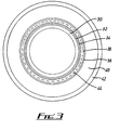
- Fig. 3 shows an embodiment of a pipe 30 having a coating incorporating a number of layers, as follow: an anti-corrosion layer 32 corresponding to the layer 12 of Figs. 1 and 2; a high temperature barrier coat 34, typically of foam or elastomer material; an impact shock absorbing coat 36, typically of soft elastomer or microcellular, semi-rigid foam; an intermediate elastomer layer, typically of high performance polyurethane elastomer; an insulating layer 40 of foam material, corresponding to the foam 14 of Figs.
- polyurethane foam which may be of various densities according to need, but typically high density foam
- an outer, protective elastomer layer 42 corresponding to the elastomer 18 of Fig. 2, typically of high performance polyurethane elastomer.
- One or more of the coating layers may incorporate one or more layers of mesh or woven reinforcing material embedded therein, typically of glass fibre or metal. Such a reinforcing mesh is indicated by broken line 44, incorporated in the shock coat 36.
Landscapes
- Engineering & Computer Science (AREA)
- General Engineering & Computer Science (AREA)
- Mechanical Engineering (AREA)
- Laminated Bodies (AREA)
- Thermal Insulation (AREA)
- Application Of Or Painting With Fluid Materials (AREA)
Claims (17)
- Verfahren zum Auftragen einer Wärmedämmungschicht auf ein Rohr (10, 30) oder dergleichen, bestehend aus den folgenden Schritten: Auftragen eines Wärmedämmungsschaumstoffs (14, 40) auf das Rohr in einer Vielzahl von getrennten Abschnitten über dem Oberflächenbereich des Rohrs und Auftragen einer äußeren Schutzschicht eines wasserdichten elastischen Polymers (18, 42), die sich zwischen den Abschnitten an das Rohr bindet, die Zwischenräume dazwischen füllt und eine äußere Schicht bildet, die den Wärmedämmungsschaum einkapselt, wobei
der Wärmedämmungsschaumstoff Polyurethanschaum ist. - Verfahren nach Anspruch 1, wobei der Wärmedämmungsschaumstoff (14, 40) anhand des Bandgießverfahrens auf das Rohr (10, 30) aufgetragen wird.
- Verfahren nach Anspruch 1 oder Anspruch 2, wobei das Wärmedämmungsmaterial (14, 40) in Abständen in ringförmigen Bändern der Länge des Rohrs (10, 30) nach aufgetragen wird.
- Verfahren nach einem der vorhergehenden Ansprüche, wobei das äußere elastische Polymer (18, 42) anhand des Bandgießverfahrens aufgetragen wird.
- Verfahren nach einem der vorhergehenden Ansprüche, wobei das Wärmedämmungsmaterial (14, 40) und das äußere elastische Polymer (18, 42) mittels programmierbarer Applikatorköpfe (16, 20) aufgetragen werden, wobei die Materialien in vorgegebenen Mustern und vorgegebenen Dicken auf das Rohr (10, 30) aufgetragen werden können.
- Verfahren nach einem der vorhergehenden Ansprüche, wobei das äußere Elastomer (18, 42) ein festes Polyurethanelastomer ist.
- Verfahren nach einem der vorhergehenden Ansprüche, wobei vor dem Auftragen des Wärmedämmungsmaterials und des äußeren elastischen Polymers eine Korrosionsschutzschicht (12, 32) auf das Rohr (10, 30) aufgetragen wird.
- Verfahren nach Anspruch 8, wobei die Korrosionsschutzschicht (12, 32) ein durch Schmelzen gebundenes Epoxidharz oder Elastomer ist.
- Verfahren nach einem der vorhergehenden Ansprüche, wobei eine Hochtemperaturgrenzschicht (34) vor dem Auftragen des Wärmedämmungsmaterials und des äußeren elastischen Polymers auf das Rohr aufgetragen wird.
- Verfahren nach einem der vorhergehenden Ansprüche, wobei eine Aufprallstoßabsorptionsschicht (36) vor dem Auftragen des Wärmedämmungsmaterials und des äußeren elastischen Polymers auf das Rohr aufgetragen wird.
- Verfahren nach einem der vorhergehenden Ansprüche, wobei eine Schicht eines elastischen Polymers (38) vor dem Auftragen des Wärmedämmungsmaterials und des äußeren elastischen Polymers auf das Rohr aufgetragen wird.
- Ein wärmegedämmtes Rohr oder dergleichen, bestehend aus einem Rohr (10, 30), auf das ein Wärmedämmungsschaumstoff (14, 40) in einer Vielzahl von getrennten Abschnitten, die über die Oberfläche des Rohrs verteilt sind, aufgetragen wird und das in einer Schutzschicht aus elastischem Polymer (18, 42), die an das Rohr (10, 30) gebunden ist und die Zwischenräume zwischen den Abschnitten füllt, eingekapselt ist, wobei
der Wärmedämmungsschaumstoff (14, 40) ein Polyurethanschaum ist. - Ein Rohr oder dergleichen nach Anspruch 12, wobei das Wärmedämmungsmaterial (14, 40) in Abständen in ringförmigen Bändern der Länge des Rohrs nach aufgetragen wird.
- Ein Rohr oder dergleichen nach Anspruch 12 oder Anspruch 13, wobei das Rohr weiterhin aus einer Korrosionsschutzschicht (12, 32) besteht, die vor dem Auftragen des Wärmedämmungsmaterials und des äußeren elastischen Polymers auf das Rohr aufgetragen wird.
- Ein Rohr oder dergleichen nach einem der Ansprüche 12 bis 14, wobei eine Hochtemperaturgrenzschicht (34) vor dem Auftragen des Wärmedämmungsmaterials und des äußeren elastischen Polymers auf das Rohr aufgetragen wird.
- Ein Rohr oder dergleichen nach einem der Ansprüche 12 bis 15, wobei eine Aufprallstoßabsorptionsschicht (36) vor dem Auftragen des Wärmedämmungsmaterials und des äußeren elastischen Polymers auf das Rohr aufgetragen wird.
- Ein Rohr oder dergleichen nach einem der Ansprüche 13 bis 16, wobei eine Schicht eines elastischen Polymers (38) vor dem Auftragen des Wärmedämmungsmaterials und des äußeren elastischen Polymers auf das Rohr aufgetragen wird.
Applications Claiming Priority (3)
| Application Number | Priority Date | Filing Date | Title |
|---|---|---|---|
| GB9311715 | 1993-06-07 | ||
| GB939311715A GB9311715D0 (en) | 1993-06-07 | 1993-06-07 | Improvements in or relating to pipe coating |
| PCT/GB1994/001235 WO1994029634A1 (en) | 1993-06-07 | 1994-06-07 | Improvements in or relating to pipe coating |
Publications (2)
| Publication Number | Publication Date |
|---|---|
| EP0704036A1 EP0704036A1 (de) | 1996-04-03 |
| EP0704036B1 true EP0704036B1 (de) | 1998-01-21 |
Family
ID=10736762
Family Applications (1)
| Application Number | Title | Priority Date | Filing Date |
|---|---|---|---|
| EP94917107A Expired - Lifetime EP0704036B1 (de) | 1993-06-07 | 1994-06-07 | Verbesserungen in bezug auf rohrbeschichtungen |
Country Status (7)
| Country | Link |
|---|---|
| US (1) | US6079452A (de) |
| EP (1) | EP0704036B1 (de) |
| AU (1) | AU6853894A (de) |
| DE (1) | DE69408141T2 (de) |
| GB (1) | GB9311715D0 (de) |
| NO (1) | NO307194B1 (de) |
| WO (1) | WO1994029634A1 (de) |
Cited By (3)
| Publication number | Priority date | Publication date | Assignee | Title |
|---|---|---|---|---|
| US8397765B2 (en) | 2008-07-25 | 2013-03-19 | Shawcor Ltd. | High temperature resistant insulation for pipe |
| US8485229B2 (en) | 2008-12-22 | 2013-07-16 | Shawcor Ltd. | Wrappable styrenic pipe insulations |
| US8714206B2 (en) | 2007-12-21 | 2014-05-06 | Shawcor Ltd. | Styrenic insulation for pipe |
Families Citing this family (30)
| Publication number | Priority date | Publication date | Assignee | Title |
|---|---|---|---|---|
| GB9609296D0 (en) * | 1996-05-03 | 1996-07-10 | Balmoral Group | Insulating coating |
| FR2785967B1 (fr) * | 1998-11-16 | 2000-12-08 | Inst Francais Du Petrole | Conduite isolee thermiquement et methode de farication |
| FR2785968B1 (fr) * | 1998-11-16 | 2001-01-12 | Inst Francais Du Petrole | Conduite isolee thermiquement par un materiau elastomere et methode de fabrication |
| US6527015B2 (en) * | 1999-07-02 | 2003-03-04 | F. Glenn Lively | Insulated pipe |
| US6397895B1 (en) | 1999-07-02 | 2002-06-04 | F. Glenn Lively | Insulated pipe |
| US8044119B2 (en) * | 1999-10-07 | 2011-10-25 | James E. Landry | Insulating material of epoxy compound, acrylic resin, ceramic particles and curing agent |
| DK200000241A (da) | 2000-02-16 | 2001-01-18 | Nkt Flexibles Is | Fleksibel armeret rørledning, samt anvendelse af samme |
| US6520261B1 (en) | 2000-04-14 | 2003-02-18 | Fmc Technologies, Inc. | Thermal insulation material for subsea equipment |
| GB0020552D0 (en) * | 2000-08-22 | 2000-10-11 | Crp Group Ltd | Pipe assembly |
| US6746761B2 (en) | 2001-07-03 | 2004-06-08 | Fmc Technologies, Inc. | High temperature silicone based subsea insulation |
| US20030051764A1 (en) * | 2001-09-20 | 2003-03-20 | Jungers Jon W. | Air handling system ductwork component and method of manufacture |
| US6953060B2 (en) * | 2001-12-19 | 2005-10-11 | Xerox Corporation | Substrate with external member |
| US7824595B2 (en) * | 2004-08-13 | 2010-11-02 | Perma-Pipe, Inc. | Method and system for cast molding a fluid conduit |
| US7530398B2 (en) * | 2004-12-20 | 2009-05-12 | Shell Oil Company | Method and apparatus for a cold flow subsea hydrocarbon production system |
| BRPI0606595B1 (pt) * | 2005-01-12 | 2018-08-07 | Shell Internationale Research Maatschappij B. V. | Método para transportar um fluido produzido através de um tubo ao mesmo tempo que limita depósitos em uma localização desejada de parede interna do tubo |
| US7661479B2 (en) * | 2005-05-25 | 2010-02-16 | Duron Systems, Inc. | Subsea insulating shroud |
| US20080072988A1 (en) * | 2006-08-22 | 2008-03-27 | Perma-Pipe, Inc. | Glass Syntactic Polyurethane Insulated Product |
| GB2466157B (en) * | 2007-10-02 | 2013-02-20 | Cameron Int Corp | Method and system for reducing heat loss from subsea structures |
| RU2428617C2 (ru) * | 2009-07-08 | 2011-09-10 | Владимир Иванович Ефимов | Способ получения теплозащитного покрытия трубопровода |
| BRPI1101090B1 (pt) * | 2011-03-21 | 2021-02-23 | Ipb-gr Indústria Mecânica Ltda | isolamento térmico de tubos de uma coluna de tubos de produção submarina de petróleo, segmento tubular e sistema para isolameto térmico de juntas de união de tubos de produção submarina de petróleo |
| ITTV20110053A1 (it) * | 2011-04-20 | 2012-10-21 | Kiasma S R L | Condotta per dragaggio integrante un dispositivogalleggiante |
| CN104707766B (zh) * | 2013-12-13 | 2017-01-04 | 哈尔滨朗格斯特节能科技有限公司 | 预制直埋保温管聚氨酯喷涂工艺 |
| CN103921078B (zh) * | 2014-05-07 | 2016-08-24 | 江苏薪泽奇机械股份有限公司 | 一种覆塑不锈钢管道的连续生产设备 |
| CN104475315A (zh) * | 2014-12-03 | 2015-04-01 | 江苏兰宇保温科技有限公司 | 管体表面聚氨酯的喷涂工艺 |
| WO2016094393A1 (en) | 2014-12-12 | 2016-06-16 | Carboline Company | Epoxy-based subsea insulation material |
| NO342327B1 (en) | 2016-01-28 | 2018-05-07 | Vetco Gray Scandinavia As | Subsea arrangement |
| IL254269B (en) * | 2017-08-31 | 2021-08-31 | Rafael Advanced Defense Systems Ltd | isophobic surfaces |
| CA3087170C (en) * | 2019-07-19 | 2023-05-09 | North American Pipe Corporation | Pipe structure having a foam core |
| AU2022383140A1 (en) * | 2021-11-07 | 2024-06-20 | SP & LE Enterprises Pty Ltd | Electrical insulation socket and method for installation thereof |
| US12270257B1 (en) | 2024-06-07 | 2025-04-08 | Command Tubular Products, Llc | Insulated drill pipes and processes of making and using same |
Family Cites Families (12)
| Publication number | Priority date | Publication date | Assignee | Title |
|---|---|---|---|---|
| US1513723A (en) * | 1924-02-02 | 1924-10-28 | Bohlander Heinrich | Heat-insulating lagging |
| US3731710A (en) * | 1965-08-27 | 1973-05-08 | Exxon | Spray foam insulated pipe |
| GB1168206A (en) * | 1968-02-20 | 1969-10-22 | Shell Int Research | An improved Pipeline |
| US3811478A (en) * | 1969-10-29 | 1974-05-21 | S Ahlqvist | Tube wall |
| OA04517A (fr) * | 1970-12-05 | 1980-03-30 | Ginsa General Inventors Sa | Procédé de réalisation d'éléments de construction comportant une structure porteuse, notamment en résine thermodurcissable armée. |
| GB1403244A (en) * | 1972-10-23 | 1975-08-28 | Uniroyal Ltd | Hoses |
| DE2836957A1 (de) * | 1978-08-24 | 1980-03-13 | Kabel Metallwerke Ghh | Waermeisoliertes leitungsrohr |
| FR2563608B1 (fr) * | 1984-04-25 | 1986-11-07 | Coflexip | Conduite calorifugee pour le transport de fluides |
| JPS6138288A (ja) * | 1984-07-31 | 1986-02-24 | 金尾 史朗 | 可撓性ホ−ス |
| DE3528205C2 (de) * | 1985-08-06 | 1994-06-30 | Rheinhold & Mahla Ag | Wärmedämmung eines Rohres zum Transport von kalten Medien |
| AU2953592A (en) * | 1991-12-07 | 1993-07-19 | Thomas Christopher Arnott | Improvements relating to pipeline insulation and anticorrosion protection |
| JP2706912B2 (ja) * | 1995-09-22 | 1998-01-28 | 東拓工業株式会社 | 断熱消音ダクト |
-
1993
- 1993-06-07 GB GB939311715A patent/GB9311715D0/en active Pending
-
1994
- 1994-06-07 AU AU68538/94A patent/AU6853894A/en not_active Abandoned
- 1994-06-07 US US08/564,226 patent/US6079452A/en not_active Expired - Fee Related
- 1994-06-07 WO PCT/GB1994/001235 patent/WO1994029634A1/en not_active Ceased
- 1994-06-07 DE DE69408141T patent/DE69408141T2/de not_active Expired - Fee Related
- 1994-06-07 EP EP94917107A patent/EP0704036B1/de not_active Expired - Lifetime
-
1995
- 1995-12-06 NO NO954941A patent/NO307194B1/no not_active IP Right Cessation
Cited By (3)
| Publication number | Priority date | Publication date | Assignee | Title |
|---|---|---|---|---|
| US8714206B2 (en) | 2007-12-21 | 2014-05-06 | Shawcor Ltd. | Styrenic insulation for pipe |
| US8397765B2 (en) | 2008-07-25 | 2013-03-19 | Shawcor Ltd. | High temperature resistant insulation for pipe |
| US8485229B2 (en) | 2008-12-22 | 2013-07-16 | Shawcor Ltd. | Wrappable styrenic pipe insulations |
Also Published As
| Publication number | Publication date |
|---|---|
| NO307194B1 (no) | 2000-02-21 |
| DE69408141T2 (de) | 1998-07-09 |
| AU6853894A (en) | 1995-01-03 |
| US6079452A (en) | 2000-06-27 |
| EP0704036A1 (de) | 1996-04-03 |
| NO954941L (no) | 1996-01-25 |
| NO954941D0 (no) | 1995-12-06 |
| DE69408141D1 (de) | 1998-02-26 |
| GB9311715D0 (en) | 1993-07-21 |
| WO1994029634A1 (en) | 1994-12-22 |
Similar Documents
| Publication | Publication Date | Title |
|---|---|---|
| EP0704036B1 (de) | Verbesserungen in bezug auf rohrbeschichtungen | |
| US4660861A (en) | Heat insulating means for piping subjected to thermal, hydrostatic and mechanical stresses, positioning thereof and processes for forming said insulating means | |
| EP0615596B1 (de) | Massnahmen zur verbesserung von isolierung und korrosionsschutz von rohrleitungen | |
| US4590971A (en) | Insulated pipeline | |
| US8579546B2 (en) | Apparatus and method for inhibiting vortex-induced vibration | |
| US4744842A (en) | Method of making a coated pipeline | |
| US6085799A (en) | Use of a buried flexible pipeline | |
| EP0921923B1 (de) | Schutz von rohrleitungsverbindungen | |
| CA2641381C (en) | Thermal insulation of flexible pipes | |
| US20080136171A1 (en) | Pipeline joint infill and protective sleeve | |
| US6827110B2 (en) | Subsea insulated pipeline with pre-cured syntactic elements and methods of manufacture | |
| US20040050442A1 (en) | Armoured, flexible pipe | |
| US6615878B2 (en) | Pipe thermally insulated by an elastomeric material and manufacturing method | |
| CA2141808C (en) | Improvements in marine and submarine apparatus | |
| US20050095380A1 (en) | Insulated subsea pipe, and materials and methods for applying thermal insulation to subsea pipe | |
| US3578029A (en) | Pipe | |
| US20080128043A1 (en) | Insulated subsea pipe with flexible insulation | |
| GB2027158A (en) | Protected and insulated pipeline | |
| WO1995033953A2 (en) | Improvements relating to pipeline insulation and anticorrosion protection | |
| GB2401921A (en) | Shrouded thermal insulation for submarine pipelines | |
| GB2166065A (en) | Insulated pipeline | |
| EP0840868B1 (de) | Rohrbeschichtung und rohr mit dieser beschichtung | |
| GB2263752A (en) | Protection of underwater pipelines and other structures | |
| GB2271410A (en) | Thermal insulation buoyancy and installation of submarine pipelines and equipment | |
| WO1996028684A9 (en) | Pipe coating |
Legal Events
| Date | Code | Title | Description |
|---|---|---|---|
| PUAI | Public reference made under article 153(3) epc to a published international application that has entered the european phase |
Free format text: ORIGINAL CODE: 0009012 |
|
| 17P | Request for examination filed |
Effective date: 19951204 |
|
| AK | Designated contracting states |
Kind code of ref document: A1 Designated state(s): DE FR GB IT NL |
|
| 17Q | First examination report despatched |
Effective date: 19960610 |
|
| GRAG | Despatch of communication of intention to grant |
Free format text: ORIGINAL CODE: EPIDOS AGRA |
|
| GRAG | Despatch of communication of intention to grant |
Free format text: ORIGINAL CODE: EPIDOS AGRA |
|
| GRAH | Despatch of communication of intention to grant a patent |
Free format text: ORIGINAL CODE: EPIDOS IGRA |
|
| GRAH | Despatch of communication of intention to grant a patent |
Free format text: ORIGINAL CODE: EPIDOS IGRA |
|
| GRAA | (expected) grant |
Free format text: ORIGINAL CODE: 0009210 |
|
| AK | Designated contracting states |
Kind code of ref document: B1 Designated state(s): DE FR GB IT NL |
|
| REF | Corresponds to: |
Ref document number: 69408141 Country of ref document: DE Date of ref document: 19980226 |
|
| ET | Fr: translation filed | ||
| ITF | It: translation for a ep patent filed | ||
| PGFP | Annual fee paid to national office [announced via postgrant information from national office to epo] |
Ref country code: DE Payment date: 19980615 Year of fee payment: 5 |
|
| PLBE | No opposition filed within time limit |
Free format text: ORIGINAL CODE: 0009261 |
|
| STAA | Information on the status of an ep patent application or granted ep patent |
Free format text: STATUS: NO OPPOSITION FILED WITHIN TIME LIMIT |
|
| 26N | No opposition filed | ||
| PGFP | Annual fee paid to national office [announced via postgrant information from national office to epo] |
Ref country code: GB Payment date: 19990524 Year of fee payment: 6 |
|
| PGFP | Annual fee paid to national office [announced via postgrant information from national office to epo] |
Ref country code: NL Payment date: 19990601 Year of fee payment: 6 |
|
| PGFP | Annual fee paid to national office [announced via postgrant information from national office to epo] |
Ref country code: FR Payment date: 19990607 Year of fee payment: 6 |
|
| PG25 | Lapsed in a contracting state [announced via postgrant information from national office to epo] |
Ref country code: DE Free format text: LAPSE BECAUSE OF NON-PAYMENT OF DUE FEES Effective date: 20000503 |
|
| PG25 | Lapsed in a contracting state [announced via postgrant information from national office to epo] |
Ref country code: GB Free format text: LAPSE BECAUSE OF NON-PAYMENT OF DUE FEES Effective date: 20000607 |
|
| PG25 | Lapsed in a contracting state [announced via postgrant information from national office to epo] |
Ref country code: NL Free format text: LAPSE BECAUSE OF NON-PAYMENT OF DUE FEES Effective date: 20010101 |
|
| GBPC | Gb: european patent ceased through non-payment of renewal fee |
Effective date: 20000607 |
|
| PG25 | Lapsed in a contracting state [announced via postgrant information from national office to epo] |
Ref country code: FR Free format text: LAPSE BECAUSE OF NON-PAYMENT OF DUE FEES Effective date: 20010228 |
|
| NLV4 | Nl: lapsed or anulled due to non-payment of the annual fee |
Effective date: 20010101 |
|
| REG | Reference to a national code |
Ref country code: FR Ref legal event code: ST |
|
| PG25 | Lapsed in a contracting state [announced via postgrant information from national office to epo] |
Ref country code: IT Free format text: LAPSE BECAUSE OF NON-PAYMENT OF DUE FEES;WARNING: LAPSES OF ITALIAN PATENTS WITH EFFECTIVE DATE BEFORE 2007 MAY HAVE OCCURRED AT ANY TIME BEFORE 2007. THE CORRECT EFFECTIVE DATE MAY BE DIFFERENT FROM THE ONE RECORDED. Effective date: 20050607 |