EP0704043B1 - Trockner zum Trocknen einer Papierbahn während der Herstellung der Papierbahn - Google Patents
Trockner zum Trocknen einer Papierbahn während der Herstellung der Papierbahn Download PDFInfo
- Publication number
- EP0704043B1 EP0704043B1 EP95910069A EP95910069A EP0704043B1 EP 0704043 B1 EP0704043 B1 EP 0704043B1 EP 95910069 A EP95910069 A EP 95910069A EP 95910069 A EP95910069 A EP 95910069A EP 0704043 B1 EP0704043 B1 EP 0704043B1
- Authority
- EP
- European Patent Office
- Prior art keywords
- nozzle
- heater
- air
- boxes
- burner
- Prior art date
- Legal status (The legal status is an assumption and is not a legal conclusion. Google has not performed a legal analysis and makes no representation as to the accuracy of the status listed.)
- Expired - Lifetime
Links
- 238000001035 drying Methods 0.000 title claims description 8
- 238000004519 manufacturing process Methods 0.000 title claims description 6
- 239000007789 gas Substances 0.000 claims description 62
- 238000002485 combustion reaction Methods 0.000 claims description 18
- 239000000567 combustion gas Substances 0.000 claims description 10
- 239000000203 mixture Substances 0.000 claims description 6
- 238000002156 mixing Methods 0.000 claims description 4
- 238000004891 communication Methods 0.000 claims description 3
- 239000012530 fluid Substances 0.000 claims 1
- 230000003134 recirculating effect Effects 0.000 claims 1
- 238000010438 heat treatment Methods 0.000 description 5
- VNWKTOKETHGBQD-UHFFFAOYSA-N methane Chemical compound C VNWKTOKETHGBQD-UHFFFAOYSA-N 0.000 description 4
- 238000010276 construction Methods 0.000 description 3
- 229910000851 Alloy steel Inorganic materials 0.000 description 2
- 238000001816 cooling Methods 0.000 description 2
- 238000009826 distribution Methods 0.000 description 2
- 239000000463 material Substances 0.000 description 2
- 239000003345 natural gas Substances 0.000 description 2
- 238000010791 quenching Methods 0.000 description 2
- 230000000171 quenching effect Effects 0.000 description 2
- UGFAIRIUMAVXCW-UHFFFAOYSA-N Carbon monoxide Chemical compound [O+]#[C-] UGFAIRIUMAVXCW-UHFFFAOYSA-N 0.000 description 1
- 229910002091 carbon monoxide Inorganic materials 0.000 description 1
- 238000010981 drying operation Methods 0.000 description 1
- 239000000446 fuel Substances 0.000 description 1
- 238000012423 maintenance Methods 0.000 description 1
- 238000000034 method Methods 0.000 description 1
- 238000012545 processing Methods 0.000 description 1
- 239000004071 soot Substances 0.000 description 1
- 238000012546 transfer Methods 0.000 description 1
Images


Classifications
-
- F—MECHANICAL ENGINEERING; LIGHTING; HEATING; WEAPONS; BLASTING
- F26—DRYING
- F26B—DRYING SOLID MATERIALS OR OBJECTS BY REMOVING LIQUID THEREFROM
- F26B13/00—Machines and apparatus for drying fabrics, fibres, yarns, or other materials in long lengths, with progressive movement
- F26B13/10—Arrangements for feeding, heating or supporting materials; Controlling movement, tension or position of materials
- F26B13/22—Arrangements of gas flames
-
- D—TEXTILES; PAPER
- D21—PAPER-MAKING; PRODUCTION OF CELLULOSE
- D21F—PAPER-MAKING MACHINES; METHODS OF PRODUCING PAPER THEREON
- D21F5/00—Dryer section of machines for making continuous webs of paper
- D21F5/02—Drying on cylinders
- D21F5/04—Drying on cylinders on two or more drying cylinders
- D21F5/042—Drying on cylinders on two or more drying cylinders in combination with suction or blowing devices
- D21F5/044—Drying on cylinders on two or more drying cylinders in combination with suction or blowing devices using air hoods over the cylinders
-
- F—MECHANICAL ENGINEERING; LIGHTING; HEATING; WEAPONS; BLASTING
- F26—DRYING
- F26B—DRYING SOLID MATERIALS OR OBJECTS BY REMOVING LIQUID THEREFROM
- F26B25/00—Details of general application not covered by group F26B21/00 or F26B23/00
- F26B25/22—Controlling the drying process in dependence on liquid content of solid materials or objects
Definitions
- This invention relates to apparatus for drying a wet paper web and controlling the moisture profile of the web during manufacture.
- a number of devices are known in the prior art for drying wet paper webs during manufacture of the paper webs.
- One well known device for drying wet paper webs is the yankee dryer which incorporates a heated drum carrying the wet paper web through the interior of a hood operatively associated therewith.
- the interior of the hood contains heated air which circulates through the hood and contacts the outer surface of the paper web.
- conventional yankee dryers the air is heated at a location exterior of the hood.
- U.S. Patent No. 3,377,056 discloses a hood having a main housing and sub-housings on either side thereof. Cooling and heating components are located in the sides of the housing. Burners are provided in the walls of plenum chambers for heating the air supplied to the paper web positioned on a yankee dryer drum.
- U.S. Patent No. 2,268,988 discloses a manifold disposed about a drum. Burners are positioned about the circumference of the drum in order to heat ink which is positioned on paper transported around the outer surface of the drum.
- U.S. Patent No. 3,163,502 is directed to a removable hood for drying a web of material conveyed around cylinders.
- Heating ducts are provided in each of the hood sections. Gas heated by a fire tube may be substituted for the heater ducts.
- the ducts are essentially identical and each provides a passage at opposite ends communicating with the exhaust air chamber.
- the apparatus of the present invention is for the purpose of efficiently and uniformly drying a wet paper web such as a web of tissue during the web manufacturing process.
- the structural elements of the apparatus cooperate to effectively use conductive, convective and radiant heating to accomplish web drying.
- the apparatus also provides for effective moisture profile control during the drying operation.
- the apparatus includes a rotatable dryer drum having a web support surface for supporting a wet paper web.
- a hood at least partially encompasses the rotatable dryer drum and defines a hood interior for receiving a wet paper web or sheet supported by the web support surface upon rotation of the dryer drum.
- a plurality of elongated heater nozzle boxes having nozzle plates are disposed in the hood interior extending across the dryer drum in the cross-machine direction and arrayed side-by-side in the machine direction.
- Each heater nozzle box defines a nozzle box interior and at least one exit opening in the nozzle plate leading from the nozzle box interior toward the dryer drum web support surface.
- a plurality of gas burners are at least partially positioned in the nozzle box interior of each of the heater nozzle boxes and arranged side-by-side along the length of the nozzle box interior for producing hot combustion gases within the nozzle box interior of each heater nozzle box. Radiant heat from the flames of the gas burner heats the nozzle plate which in turn radiates heat to the sheet. The hot combustion gases mix with supply air and flow through the exit openings in the nozzle plate at high velocity to promote convection heat transfer to the sheet.
- each gas burner includes a burner nozzle extending along a predetermined width portion or slice of the wet paper web supported by the dryer drum web support surface.
- Each gas burner additionally includes an aspirator for mixing air and flammable gas and delivering the air and flammable gas mixture mixed thereby to a burner nozzle.
- the heater nozzle boxes are spaced from each other, each said heater nozzle box including opposed side walls. Side walls of adjacent heater nozzle boxes define return air flow paths for receiving the supply air and combustion gases which have exited the exit openings of the heater nozzle boxes.
- the volume of supply air is quite large compared to the volume of combustion gases.
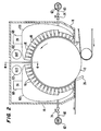
- a yankee dryer drum 10 is illustrated. As is conventional, the dryer drum is heated and has a web support surface for supporting a wet paper web 12 and delivering the paper web into the interior of a dryer hood 14 upon rotation of the dryer drum.
- a plurality of elongated heater nozzle boxes 16 are disposed in the interior of hood 14 and extend across the dryer drum 10 in the cross-machine direction.
- the heater nozzle boxes are arrayed side-by-side in the machine direction and spaced from one another.
- Each of the heater nozzle boxes defines a nozzle box interior 18 (Figs. 4, 5 and 6).
- Each heater nozzle box 16 includes side walls 22, end walls 24, a cap wall 20 and a nozzle plate 26. All of the aforesaid walls may be constructed of any suitable material such as high temperature alloy steel. Likewise, nozzle plate 26 may suitably be constructed of high temperature alloy steel.
- the heater box nozzle plates each define a plurality of exit openings 28 along the lengths thereof, said exit openings providing communication with the interior of the heater nozzle box.
- each of the heater nozzle boxes Positioned within the interior of each of the heater nozzle boxes are a plurality of gas burners 30.
- the gas burners 30 are arranged side-by-side along the length of the nozzle box interior and are for producing hot combustion gases within the nozzle box interior of each heater nozzle box.
- Each gas burner includes a burner nozzle 32, the burner nozzles being in the form of elongated burner nozzle segments defining a plurality of exit openings through which heated combustion gases are directed toward the nozzle plate 26. Rather then a plurality of exit openings, a single continuous slot could be utilized.
- Figs. 4 and 5 show flames 36 being emitted from the exit openings of the burner nozzles.
- Each gas burner also includes an aspirator 40 in the form of a venturi which will mix air and flammable gas, maintain the gas and combustion air in ratio, and deliver the air and flammable gas mixture mixed thereby to a burner nozzle.
- an aspirator 40 in the form of a venturi which will mix air and flammable gas, maintain the gas and combustion air in ratio, and deliver the air and flammable gas mixture mixed thereby to a burner nozzle.
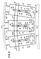
- each burner nozzle 32 Positioned on opposed sides of each burner nozzle 32 are flame shield plates 42.
- the burner nozzles and the respective flame shields extend along a predetermined width portion or slice of the wet paper web supported by the dryer drum web support surface.
- the flame shield plates 42 of each pair thereof are connected to each burner nozzle adjacent to the nozzle exit.
- an intermediate support plate 44 integral with the pair of flame shield plates 42 serves to provide such support, the support plates 44 having an aperture therein which fits about the associated gas burner 30 above the burner nozzle 32.
- both the burner nozzles and the support plates may be removed from the rest of the gas burner structures, as for example by providing a screw interconnection therebetween, to allow replacement and/or maintenance of the burner nozzles and flame shield plates.
- each pair of shield plates flare outwardly away from each other as illustrated and have distal ends spaced from the nozzle exit and also spaced from the heater box nozzle plate 26.
- the shield plates of each pair of shield plates are cut on an angle. Such a configuration has been found to facilitate removal of an individual set or pair of shield plates from the associated gas burner by avoiding interference contact between the pair of plates being removed and one or more adjacent pairs when the pair is unscrewed from the burner structure.
- the flame shield plates assist in directing the combustion gases from the burner nozzles to the nozzle plate. Additionally, the flame shield plates resist quenching of flame at the burner nozzles.
- the flame is very sensitive to cooling. When the flame is cooled before combustion is complete, carbon monoxide, soot and other undesirable products result. This process is known as flame quenching.
- the flame shield operates to protect the flame from the large volume of supply air flowing to the nozzles from associated crescent headers as will be described in greater detail below. The supply air is relatively cool as compared to flame temperature.
- the flame shields form a continuous trough across the width of the sheet on the dryer drum. Their segmented construction relieves stress from thermal expansion and provides ease of manufacture and assembly.
- the angular shape permits any particular bar burner to be threaded out of its aspirator by rotating the adjacent flame shields ninety degrees, as illustrated in Fig. 6.
- Another feature of the apparatus of the present invention is the use of air mixing elements in the form of bars or plates 50 which project inwardly from heater nozzle box side walls 22 into the interior of the heater nozzle box at a location between the distal ends of flame shield plates 42 and heater box nozzle plate 26.
- the air mixer elements 50 promote turbulence within the nozzle box interior 18 and thus promote thorough mixing between the products of combustion and the large volume of recirculated supply air.
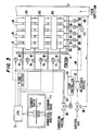
- An important aspect of the apparatus is the distribution system for distributing flammable gas, such as natural gas, and combustion air to the gas burners.
- a plurality of air headers 60 extend between the heater nozzle boxes 16.
- the air headers 60 are arrayed in the machine direction and connect at one end thereof to an air supply line 62 which in turn is connected to a source of combustion air through a control valve 66.
- Each of the air headers 60 supplies combustion air to the aspirator 40 of a gas burner 30 in each of the heater nozzle boxes.
- the air headers include expansion joints 72 between adjacent heater nozzle boxes to compensate for temperature changes.
- Control valves 74 are in operative association with each of the air headers 60 and placed between the air supply line 62 and the hood 14. Thus the flow of combustion air passing through the air headers 60 can be controlled. If desired, the control valves 74 can be automatically controlled to control the flow of air therethrough.
- Fig. 3 illustrates such an arrangement wherein a suitably programmed central processing unit 75 operates valves 74 based on inputs received from a scanning moisture gauge 77 of any known commercial type which monitors the moisture profile of web 12 after it is creped from the yankee. Air flow through individual control valves can be modified in response to the sensed moisture profile to control the moisture profile.
- a suitably programmed central processing unit 75 operates valves 74 based on inputs received from a scanning moisture gauge 77 of any known commercial type which monitors the moisture profile of web 12 after it is creped from the yankee. Air flow through individual control valves can be modified in response to the sensed moisture profile to control the moisture profile.
- a flammable gas header 80 is also operatively associated with the heater nozzle boxes 16. More particularly, a flammable gas header 80 extends the length of each of the heater nozzle boxes in the cross-machine direction. Flammable gas feeder lines 82 lead from the flammable gas headers 80 to the aspirators 40, it being understood that one such flammable gas feeder line 82 is connected to each aspirator.
- the aspirator being in the nature of a venturi, draws the relatively unpressurized gas into the interior of the aspirator as a result of the flow of combustion air through the aspirator. Thus, when the supply of combustion air to any particular aspirator is modulated, the flow of gas into that particular aspirator will also be modulated.
- the continuously flowing combustion air cools the aspirator and burner below the ignition temperature of the gas.
- Flammable gas typically natural gas
- a manifold 84 Preferably the manifold 84 also has a backpressure regulator 86 operatively associated therewith.
- the back pressure regulator is a diaphragm actuated valve of conventional construction and controls the gas pressure at the regulator to match the supply air pressure.
- An adjustable orifice valve 87 is located downstream from the regulator 86 and provides a means to adjust the fuel to air ratio for all the burners with a single adjustment. This restriction results in the gas header pressure being slightly less than the supply air pressure.
- each nozzle box is equipped with an igniter and a flame detector.
- the flame detector is mounted at the opposite end from the igniter to ensure that the bank of burners has ignited over the full width of the machine.
- Gas cut-off valves 88 are disposed in headers 80 between the hood and the flammable gas manifold 84. The gas cut-off valves provide positive gas shut off to an entire nozzle box in the event of an unsafe condition such as loss of flame. This is to be compared with the operation of the individual combustion air valves 74 which modulate the air flow (and via the aspirators, the gas flow) to level the moisture profile.
- wet paper web is partially dried by the drum because the underside thereof is in direct engagement with the heated drum web support surface.
- crescent headers 100 receive recirculated supply fan air from the hood interior through a duct 68 in communication with the hood interior through one or more exit ports 102.
- the fan means for providing such circulation is conventional and has not been illustrated.
- the recirculated supply air mixes with the combustion gases from gas burners 30.
- a tap line leads from the interior of duct 68 to backpressure regulator 86, the objective being to maintain the gas flowing through manifold 84 at the same pressure as the supply fan air.
- a temperature controller 110 is operatively associated with control valve 66 to control the flow of combustion air in response to the temperature sensed by temperature sensor 112 of the recirculated air in duct 68.
Landscapes
- Engineering & Computer Science (AREA)
- Mechanical Engineering (AREA)
- General Engineering & Computer Science (AREA)
- Textile Engineering (AREA)
- Drying Of Solid Materials (AREA)
- Paper (AREA)
Claims (11)
- Vorrichtung zum Trocknen einer nassen Papierbahn während der Herstellung der Papierbahn, wobei die Vorrichtung in Kombination folgendes umfaßt:eine drehbare Trocknertrommel mit einer Bahnträgerfläche zum Tragen einer nassen Papierbahn;eine Haube, die zumindest teilweise die drehbare Trocknertrommel umgibt und einen Haubeninnenraum zur Aufnahme einer nassen Papierbahn, die von der Bahnträgerfläche bei Drehung der Trocknertrommel getragen wird, definiert;eine Mehrzahl von länglichen Heizblasdüsenkästen, die in dem Haubeninnenraum angeordnet sind und sich über die Trocknertrommel quer zur Maschinenrichtung erstrecken und Seite an Seite in Maschinenrichtung angeordnet sind, wobei jeder der Heizblasdüsenkästen einen Blasdüsenkasteninnenraum und mindestens eine Auslaßöffnung definiert, die von dem Blasdüsenkasteninnenraum zu der Bahnträgerfläche der Trocknertrommel führt;eine Mehrzahl von Gasbrennern, die zumindest teilweise in dem Blasdüsenkasteninnenraum jedes der Heizblasdüsenkästen positioniert und Seite an Seite entlang der Länge des Blasdüsenkasteninnenraums angeordnet sind, um heiße Verbrennungsgase innerhalb des Blasdüsenkasteninnenraums jedes Heizblasdüsenkastens zu erzeugen, wobei die Heizblasdüsenkästen Strahlungswärmeenergie auf eine nasse Papierbahn auf der Bahnträgerfläche der Trocknertrommel aufbringen und erwärmte Verbrennungsluft von den Blasdüsenkasteninnenräumen durch die Auslaßöffnungen der Heizblasdüsenkästen zu der nassen Papierbahn lenken, die von der Bahnträgerfläche der Trocknertrommel getragen wird.
- Vorrichtung nach Anspruch 1, wobei jeder der Gasbrenner eine Brennerdüse umfaßt, die sich entlang einem vorbestimmten Breitenteil der nassen Papierbahn erstreckt, die von der Bahnträgerfläche der Trocknertrommel getragen wird, und vorzugsweise wobei die Brennerdüsen längliche Brennerdüsensegmente umfassen, wobei jedes längliche Brennerdüsensegment zumindest eine Auslaßöffnung definiert.
- Vorrichtung nach Anspruch 1 oder 2, wobei die Heizblasdüsenkästen voneinander beabstandet sind, jeder Heizblasdüsenkasten gegenüberliegende Seitenwände aufweist und die Seitenwände benachbarter Heizblasdüsenkästen Luftrückströmungswege zur Aufnahme von Verbrennungsluft definieren, nachdem die Verbrennungsluft aus den Auslaßöffnungen der Heizblasdüsenkästen ausgetreten ist.
- Vorrichtung nach einem der vorangehenden Ansprüche, wobei jeder Gasbrenner zusätzlich eine Saugeinrichtung zum Mischen von Luft und brennbarem Gas und zum Abgeben der so gemischten Mischung aus Luft und brennbarem Gas an eine Brennerdüse umfaßt, und vorzugsweise wobei die Vorrichtung zusätzlich mindestens ein Luftsammelrohr umfaßt, das sich zwischen der Mehrzahl länglicher Heizblasdüsenkästen in die Maschinenrichtung zur Abgabe von Verbrennungsluft an die Saugeinrichtungen der Gasbrenner in den Heizblasdüsenkästen erstreckt, und vorzugsweise wobei die Vorrichtung zusätzlich Leitungsmittel für brennbares Gas umfaßt, um brennbares Gas zu den Saugeinrichtungen der Gasbrenner in den Heizblasdüsenkästen zu leiten.
- Vorrichtung nach einem der vorangehenden Ansprüche, wobei die Vorrichtung zusätzlich eine Mehrzahl von Flammenabschirmungen umfaßt, die in jedem Heizblasdüsenkasten angeordnet sind und sich von jeder Brennerdüse im Inneren des Blasdüsenkastens des Heizblasdüsenkastens nach außen erstrecken.
- Vorrichtung nach Anspruch 5, wobei jede Brennerdüse eine Düsenöffnung aufweist und wobei jede Flammenabschirmung ein Paar von Abschirmplatten umfaßt, die mit jeder Brennerdüse neben der Düsenöffnung verbunden sind, wobei die Abschirmplatten jedes Paares von Abschirmplatten nach außen auseinandergehen und distale Enden aufweisen, die von der Düsenöffnung beabstandet sind, und vorzugsweise wobei die Abschirmplatten jedes Paares von Abschirmplatten aneinander befestigt und lösbar mit einer Brennerdüse verbunden sind und vorzugsweise wobei die Abschirmplatten jedes Paares von Abschirmplatten in einem Winkel geschnitten sind, um deren Entfernung von einer Brennerdüse zu erleichtern.
- Vorrichtung nach Anspruch 6, wobei die Vorrichtung zusätzlich Luftmischelemente umfaßt, die an die Heizblasdüsenkästen angeschlossen sind und sich in die Innenräume der Blasdüsenkästen zwischen den distalen Enden der Abschirmplatten und der mindestens einen Auslaßöffnung der Heizblasdüsenkästen erstrecken, um eine Wirbelströmung zu erzeugen und das Mischen von Gasen in den Innenräumen der Blasdüsenkästen zu erleichtern.
- Vorrichtung nach einem der vorangehenden Ansprüche, wobei jeder Heizblasdüsenkasten eine Düsenplatte umfaßt, die mindestens eine Auslaßöffnung definiert, wobei sich die Düsenplatte über die Trocknertrommel quer zur Maschinenrichtung erstreckt, wobei die Mehrzahl von länglichen Heizblasdüsenkästen mit ihren entsprechenden Düsenplatten nahe benachbart zu der Bahnträgerfläche der drehbaren Trocknertrommel angeordnet ist.
- Vorrichtung nach Anspruch 4, wobei die Saugeinrichtung zumindest teilweise innerhalb der Innenräume der Blasdüsenkästen angeordnet sind, wobei die Vorrichtung zusätzlich Verbrennungsluftabgabemittel umfaßt, die mindestens ein Luftsammelrohr enthalten, das sich in die Innenräume der Blasdüsenkästen erstreckt und in Fluidstromverbindung mit den Saugeinrichtungen steht, und/oder wobei die Vorrichtung zusätzlich Zuluftventilmittel zur Steuerung des Luftstroms und Stroms von brennbarem Gas zu den Saugeinrichtungen umfaßt.
- Vorrichtung nach Anspruch 4, wobei das Leitungsmittel für brennbares Gas ein Sammelrohr für brennbares Gas umfaßt, das betriebsmäßig mit dem Heizblasdüsenkasten verbunden ist und sich im wesentlichen entlang der Länge jedes Heizblasdüsenkastens quer zur Maschinenrichtung erstreckt, und Zuleitungen für brennbares Gas, die sich zwischen dem Sammelrohr für brennbares Gas zu jedem der Saugeinrichtung in dem entsprechenden Heizblasdüsenkasten erstrecken, und vorzugsweise wobei die Vorrichtung zusätzlich Ventilmittel umfaßt, die betriebsmäßig mit jeder Zuleitung für brennbares Gas verbunden sind, um den Strom des brennbaren Gases zu allen Gasbrennern in einem Heizblasdüsenkasten zu beenden, und vorzugsweise wobei die Vorrichtung zusätzlich Zündungsmittel zum Zünden der Gasbrenner in jedem Blasdüsenkasten sowie Flammendetektormittel zum Erfassen einer Flamme von den Gasbrennern in jedem Blasdüsenkasten umfaßt.
- Vorrichtung nach einem der vorangehenden Ansprüche, wobei die Vorrichtung zusätzlich eine Mehrzahl bogenförmiger Sammelrohre in der Haube umfaßt, die mit den Blasdüsenkästen zur Rezirkulierung der Haubenluft durch die Blasdüsenkästen verbunden sind, um diese mit den heißen Verbrennungsgasen zu vermischen, die von den Gasbrennern in den Blasdüsenkästen erzeugt werden.
Applications Claiming Priority (3)
| Application Number | Priority Date | Filing Date | Title |
|---|---|---|---|
| US225812 | 1994-04-11 | ||
| US08/225,812 US5416979A (en) | 1994-04-11 | 1994-04-11 | Paper web dryer and paper moisture profiling system |
| PCT/US1994/013980 WO1995027879A1 (en) | 1994-04-11 | 1994-12-12 | Paper web dryer and paper moisture profiling system |
Publications (3)
| Publication Number | Publication Date |
|---|---|
| EP0704043A1 EP0704043A1 (de) | 1996-04-03 |
| EP0704043A4 EP0704043A4 (de) | 1996-12-18 |
| EP0704043B1 true EP0704043B1 (de) | 1998-05-06 |
Family
ID=22846354
Family Applications (1)
| Application Number | Title | Priority Date | Filing Date |
|---|---|---|---|
| EP95910069A Expired - Lifetime EP0704043B1 (de) | 1994-04-11 | 1994-12-12 | Trockner zum Trocknen einer Papierbahn während der Herstellung der Papierbahn |
Country Status (6)
| Country | Link |
|---|---|
| US (1) | US5416979A (de) |
| EP (1) | EP0704043B1 (de) |
| CA (1) | CA2164942C (de) |
| DE (1) | DE69410091T2 (de) |
| ES (1) | ES2116733T3 (de) |
| WO (1) | WO1995027879A1 (de) |
Families Citing this family (28)
| Publication number | Priority date | Publication date | Assignee | Title |
|---|---|---|---|---|
| US5784804A (en) * | 1996-03-25 | 1998-07-28 | Asea Brown Boveri, Inc. | Yankee hood with integral air heating system |
| US5915813A (en) * | 1996-05-21 | 1999-06-29 | Fort James Corporation | Apparatus and method for drying a wet web and modifying the moisture profile thereof |
| US5937538A (en) * | 1996-05-21 | 1999-08-17 | Fort James Corporation | Through air dryer apparatus for drying webs |
| US5713138A (en) * | 1996-08-23 | 1998-02-03 | Research, Incorporated | Coating dryer system |
| CA2206382C (en) * | 1997-05-28 | 2000-08-22 | Asea Brown Boveri Inc. | Curl and profile correction with high velocity hoods |
| CA2216591C (en) * | 1997-09-24 | 2004-05-11 | Asea Brown Boveri Inc. | High temperature yankee hood |
| FI104000B (fi) * | 1998-04-03 | 1999-10-29 | Valmet Corp | Telan, sylinterin tai vastaavan ympärille sovitettu päällepuhallusjärjestelmä paperikoneen tai vastaavan kuivatusosassa |
| US6079116A (en) * | 1998-11-06 | 2000-06-27 | Valmet-Karlstad Ab | Duct configuration for a through-air drying apparatus in a papermaking machine |
| US6397489B1 (en) * | 2000-08-25 | 2002-06-04 | The University Of Chicago | Multiport cylinder dryer with low thermal resistance and high heat transfer |
| US6631566B2 (en) * | 2000-09-18 | 2003-10-14 | Kimberly-Clark Worldwide, Inc. | Method of drying a web |
| FI116731B (fi) * | 2001-06-26 | 2006-02-15 | Metso Paper Inc | Päällepuhallusjärjestelmä paperikoneen tai vastaavan kuivatusosassa |
| US6877979B2 (en) * | 2002-11-14 | 2005-04-12 | Gas Technology Institute | Process and apparatus for indirect-fired heating and drying |
| US6964117B2 (en) | 2002-12-20 | 2005-11-15 | Metso Paper Usa, Inc. | Method and apparatus for adjusting a moisture profile in a web |
| DE10325140B4 (de) * | 2003-06-04 | 2014-12-31 | Lts Lohmann Therapie-Systeme Ag | Direktbeschichtungsverfahren und dafür geeignete Vorrichtung |
| DE102004006515A1 (de) * | 2004-02-10 | 2005-08-25 | Voith Paper Patent Gmbh | Verfahren zur Beheizung einer Walze |
| FR2867263B1 (fr) * | 2004-03-02 | 2006-05-26 | Solaronics Irt | Installation de sechage pour une bande defilante, notamment pour une bande de papier |
| WO2005085730A2 (en) * | 2004-03-02 | 2005-09-15 | Nv Bekaert Sa | Infrared drier installation for passing web |
| AT413709B (de) * | 2004-06-28 | 2006-05-15 | Andritz Ag Maschf | Vorrichtung zum kontinuierlichen trocknen einer faserstoffbahn |
| DE102005000795A1 (de) * | 2005-01-05 | 2006-07-13 | Voith Paper Patent Gmbh | Vorrichtung und Verfahren zur Herstellung und/oder Veredelung einer Faserstoffbahn |
| US7716850B2 (en) * | 2006-05-03 | 2010-05-18 | Georgia-Pacific Consumer Products Lp | Energy-efficient yankee dryer hood system |
| CN102733242B (zh) * | 2011-04-10 | 2015-02-11 | 上海东冠纸业有限公司 | 一种烘缸气罩用鼓风装置 |
| US9481777B2 (en) | 2012-03-30 | 2016-11-01 | The Procter & Gamble Company | Method of dewatering in a continuous high internal phase emulsion foam forming process |
| WO2015030766A1 (en) | 2013-08-29 | 2015-03-05 | Hewlett-Packard Development Company, L.P. | Variable humidity drying |
| EP2963176B1 (de) * | 2015-04-23 | 2017-03-15 | Valmet S.p.A. | Yankee-trockenhaubenanordnung, yankee-trockenzylinder mit einer yankee-trockenhaubenanordnung und verfahren zur trocknung einer faserbahn |
| EP3170480A1 (de) * | 2015-11-18 | 2017-05-24 | The Procter and Gamble Company | Vorrichtung und verfahren zum recyceln von erwärmtem gas |
| CN120740278A (zh) * | 2018-05-01 | 2025-10-03 | 瓦尔梅特股份有限公司 | 具有热空气注入的空气穿透干燥系统和方法 |
| SE542214C2 (en) | 2018-10-12 | 2020-03-10 | Valmet Oy | A tissue paper making machine and a method of operating a tissue paper making machine |
| IT202200026445A1 (it) | 2022-12-22 | 2024-06-22 | Toscotec S P A | Macchina per la produzione della carta. |
Family Cites Families (4)
| Publication number | Priority date | Publication date | Assignee | Title |
|---|---|---|---|---|
| US2268988A (en) * | 1939-08-08 | 1942-01-06 | Interchem Corp | Method and apparatus for drying printing ink |
| US2576274A (en) * | 1947-10-04 | 1951-11-27 | Orr Felt & Blanket Company | Drying and curing apparatus |
| US3163502A (en) * | 1960-10-13 | 1964-12-29 | Beloit Corp | Removable hood for a drying cylinder |
| SE342273B (de) * | 1965-09-23 | 1972-01-31 | Svenska Flaektfabriken Ab |
-
1994
- 1994-04-11 US US08/225,812 patent/US5416979A/en not_active Expired - Fee Related
- 1994-12-12 ES ES95910069T patent/ES2116733T3/es not_active Expired - Lifetime
- 1994-12-12 EP EP95910069A patent/EP0704043B1/de not_active Expired - Lifetime
- 1994-12-12 CA CA002164942A patent/CA2164942C/en not_active Expired - Fee Related
- 1994-12-12 WO PCT/US1994/013980 patent/WO1995027879A1/en not_active Ceased
- 1994-12-12 DE DE69410091T patent/DE69410091T2/de not_active Expired - Fee Related
Also Published As
| Publication number | Publication date |
|---|---|
| EP0704043A4 (de) | 1996-12-18 |
| EP0704043A1 (de) | 1996-04-03 |
| CA2164942C (en) | 1999-04-13 |
| WO1995027879A1 (en) | 1995-10-19 |
| ES2116733T3 (es) | 1998-07-16 |
| CA2164942A1 (en) | 1995-10-19 |
| US5416979A (en) | 1995-05-23 |
| DE69410091T2 (de) | 1998-09-03 |
| DE69410091D1 (de) | 1998-06-10 |
Similar Documents
| Publication | Publication Date | Title |
|---|---|---|
| EP0704043B1 (de) | Trockner zum Trocknen einer Papierbahn während der Herstellung der Papierbahn | |
| US5465504A (en) | System for modifying the moisture profile of a paper web | |
| US5937538A (en) | Through air dryer apparatus for drying webs | |
| US5573396A (en) | Low emissions burner | |
| JPH01321994A (ja) | 移動ウェブの乾燥方法および組み合わせ乾燥機 | |
| EP0808942B1 (de) | Vorrichtung und Verfahren zum Trocknen einer feuchten Bahn und zum Modifizieren seines Feuchtigkeitsprofils | |
| US4989348A (en) | Continuous-flow dryer for material webs, in particular offset dryer process for the thermal operation of a continuous-flow dryer | |
| EP0708301B1 (de) | Mit Gas befeuerte Trocknungsvorrichtung | |
| JPH07508827A (ja) | チューブバーナ | |
| EP1588112B1 (de) | Verfahren und vorrichtung zum einstellen eines feuchtigkeitsprofils in einem vlies | |
| EP0857931B1 (de) | Gasbeheizter Trockenzylinder | |
| US5784804A (en) | Yankee hood with integral air heating system | |
| EP3870753B1 (de) | Yankee-trockenhaubenanordnung, yankee-trockenzylinder mit einer yankee-trockenhaubenanordnung und verfahren zur trocknung einer faserbahn | |
| EP3405612B1 (de) | Yankee-trockenzylinder mit dampflosem betrieb | |
| US4286945A (en) | Wall fired duct heater | |
| US6412190B1 (en) | Infrared and hot air dryer combination | |
| NO163905B (no) | Ikke-forurensende ba sis av salt- eller ferskvann og anvendelse av dette i borevaesker. | |
| JP3144345U (ja) | 温風機における空気加熱のための構造 | |
| JP2752322B2 (ja) | スクリードの加熱装置 | |
| FI124517B (en) | Method and system for stabilizing the operation of an overhead dryer | |
| KR100382667B1 (ko) | 강제대류가열장치및그내에서의유리판의가열방법 | |
| JP2000503379A (ja) | ガラスシートを加熱するための強制対流加熱装置および方法 | |
| JPH04108604U (ja) | 路面加熱装置 | |
| CZ20001861A3 (cs) | Keramický plynový hořák a regenerační tepelný generátor, vybavený keramickým plynovým hořákem | |
| GB2036270A (en) | Soaking pits for ingots |
Legal Events
| Date | Code | Title | Description |
|---|---|---|---|
| PUAI | Public reference made under article 153(3) epc to a published international application that has entered the european phase |
Free format text: ORIGINAL CODE: 0009012 |
|
| AK | Designated contracting states |
Kind code of ref document: A1 Designated state(s): DE ES FR GB IT |
|
| 17P | Request for examination filed |
Effective date: 19960319 |
|
| A4 | Supplementary search report drawn up and despatched |
Effective date: 19961105 |
|
| AK | Designated contracting states |
Kind code of ref document: A4 Designated state(s): DE ES FR GB IT |
|
| GRAG | Despatch of communication of intention to grant |
Free format text: ORIGINAL CODE: EPIDOS AGRA |
|
| 17Q | First examination report despatched |
Effective date: 19970516 |
|
| GRAG | Despatch of communication of intention to grant |
Free format text: ORIGINAL CODE: EPIDOS AGRA |
|
| GRAH | Despatch of communication of intention to grant a patent |
Free format text: ORIGINAL CODE: EPIDOS IGRA |
|
| GRAH | Despatch of communication of intention to grant a patent |
Free format text: ORIGINAL CODE: EPIDOS IGRA |
|
| GRAA | (expected) grant |
Free format text: ORIGINAL CODE: 0009210 |
|
| RAP1 | Party data changed (applicant data changed or rights of an application transferred) |
Owner name: FORT JAMES OPERATING COMPANY |
|
| AK | Designated contracting states |
Kind code of ref document: B1 Designated state(s): DE ES FR GB IT |
|
| ITF | It: translation for a ep patent filed | ||
| ET | Fr: translation filed | ||
| REF | Corresponds to: |
Ref document number: 69410091 Country of ref document: DE Date of ref document: 19980610 |
|
| REG | Reference to a national code |
Ref country code: ES Ref legal event code: FG2A Ref document number: 2116733 Country of ref document: ES Kind code of ref document: T3 |
|
| PLBE | No opposition filed within time limit |
Free format text: ORIGINAL CODE: 0009261 |
|
| STAA | Information on the status of an ep patent application or granted ep patent |
Free format text: STATUS: NO OPPOSITION FILED WITHIN TIME LIMIT |
|
| 26N | No opposition filed | ||
| REG | Reference to a national code |
Ref country code: GB Ref legal event code: IF02 |
|
| PGFP | Annual fee paid to national office [announced via postgrant information from national office to epo] |
Ref country code: FR Payment date: 20051110 Year of fee payment: 12 |
|
| PGFP | Annual fee paid to national office [announced via postgrant information from national office to epo] |
Ref country code: GB Payment date: 20051114 Year of fee payment: 12 |
|
| PGFP | Annual fee paid to national office [announced via postgrant information from national office to epo] |
Ref country code: DE Payment date: 20051117 Year of fee payment: 12 |
|
| PGFP | Annual fee paid to national office [announced via postgrant information from national office to epo] |
Ref country code: ES Payment date: 20051205 Year of fee payment: 12 |
|
| PGFP | Annual fee paid to national office [announced via postgrant information from national office to epo] |
Ref country code: IT Payment date: 20061231 Year of fee payment: 13 |
|
| PG25 | Lapsed in a contracting state [announced via postgrant information from national office to epo] |
Ref country code: DE Free format text: LAPSE BECAUSE OF NON-PAYMENT OF DUE FEES Effective date: 20070703 |
|
| GBPC | Gb: european patent ceased through non-payment of renewal fee |
Effective date: 20061212 |
|
| REG | Reference to a national code |
Ref country code: FR Ref legal event code: ST Effective date: 20070831 |
|
| PG25 | Lapsed in a contracting state [announced via postgrant information from national office to epo] |
Ref country code: GB Free format text: LAPSE BECAUSE OF NON-PAYMENT OF DUE FEES Effective date: 20061212 |
|
| REG | Reference to a national code |
Ref country code: ES Ref legal event code: FD2A Effective date: 20061213 |
|
| PG25 | Lapsed in a contracting state [announced via postgrant information from national office to epo] |
Ref country code: FR Free format text: LAPSE BECAUSE OF NON-PAYMENT OF DUE FEES Effective date: 20070102 Ref country code: ES Free format text: LAPSE BECAUSE OF NON-PAYMENT OF DUE FEES Effective date: 20061213 |
|
| PG25 | Lapsed in a contracting state [announced via postgrant information from national office to epo] |
Ref country code: IT Free format text: LAPSE BECAUSE OF NON-PAYMENT OF DUE FEES Effective date: 20071212 |