EP0704048B1 - Suppresseur de signaux d'activation pour gyroscope laser annulaire active - Google Patents
Suppresseur de signaux d'activation pour gyroscope laser annulaire active Download PDFInfo
- Publication number
- EP0704048B1 EP0704048B1 EP94930554A EP94930554A EP0704048B1 EP 0704048 B1 EP0704048 B1 EP 0704048B1 EP 94930554 A EP94930554 A EP 94930554A EP 94930554 A EP94930554 A EP 94930554A EP 0704048 B1 EP0704048 B1 EP 0704048B1
- Authority
- EP
- European Patent Office
- Prior art keywords
- output
- dither
- angle
- gain
- gyro
- Prior art date
- Legal status (The legal status is an assumption and is not a legal conclusion. Google has not performed a legal analysis and makes no representation as to the accuracy of the status listed.)
- Expired - Lifetime
Links
Images


Classifications
-
- G—PHYSICS
- G01—MEASURING; TESTING
- G01C—MEASURING DISTANCES, LEVELS OR BEARINGS; SURVEYING; NAVIGATION; GYROSCOPIC INSTRUMENTS; PHOTOGRAMMETRY OR VIDEOGRAMMETRY
- G01C19/00—Gyroscopes; Turn-sensitive devices using vibrating masses; Turn-sensitive devices without moving masses; Measuring angular rate using gyroscopic effects
- G01C19/58—Turn-sensitive devices without moving masses
- G01C19/64—Gyrometers using the Sagnac effect, i.e. rotation-induced shifts between counter-rotating electromagnetic beams
- G01C19/66—Ring laser gyrometers
- G01C19/661—Ring laser gyrometers details
- G01C19/662—Ring laser gyrometers details signal readout; dither compensators
- G01C19/664—Ring laser gyrometers details signal readout; dither compensators means for removing the dither signal
Definitions
- This invention relates generally to a method and apparatus for removing the dither signal component from the inertial output of a laser gyro and more particularly to a method and apparatus for dither stripper gain correction.
- Ring laser angular rate sensors also called laser gyros
- ring laser angular rate sensors are well known in the art.
- a ring laser angular rate sensor is US Patent No. 4,751,718 issued to Hanse, et al.
- Present day ring laser angular rate sensors include a thermally and mechanically stable laser block having a plurality of formed cavities for enclosing a gap. Minors are placed at the extremities of the cavities for reflecting laser beams and providing an optical closed-loop path.
- lock-in Associated with such sensors is an undesirable phenomenon called lock-in which has been recognized for some time in the prior art.
- the counter-propagating laser beams tend to lock together to a common frequency.
- the ring laser gyro may be biased by an alternating bias technique such as that shown and described in U.S. Pat. No. 3,373,650 issued in the name of J. B. Killpatrick.
- the alternating bias technique is usually referred to as dithering, and may be implemented by a variety of ways including electro-optical and mechanical schemes.
- the sensor readout signal will contain not only inertial rate information, but will also contain a signal component directly related to the dithering, or alternating bias, of the sensor.
- Dither motors of the prior art usually have a suspension system which includes, for example, an outer rim, a central hub member and a plurality of three dither motor reeds which project radially from the hub member and are connected between the hub member and the rim.
- a set of piezo-electric elements is connected to the suspension system.
- the set of piezo-electric elements serves as an actuator.
- the suspension system When actuated through the application of an electrical signal to the piezo-electric elements, the suspension system operates as a dither motor which causes the block of the sensor to oscillate angularly at the natural mechanical resonant frequency of the suspension system. This dither motion is superimposed upon the inertial rotation of the sensor in inertial space.
- Such dither motors may be used in connection with a single laser gyro, or to dither multiple laser gyros.
- the prior art includes various approaches to recover inertial rotation data free from dither effects.
- the gyro output comprises the sum of the base angular motion and the gyro dither motion relative to the mounting base. This is true whether the sensor readout is mounted directly on the sensor, as in the case of a laser block mounted sensor readout, or fixed relative to the sensor mounting base like that shown in the aforementioned patent.
- the signal contribution in the sensor readout signal due to the alternating bias is herein referred to as the dither signal component.
- the dither signal component in the readout signal generally needs to be minimized or removed to avoid control problems, particularly in block mounted readout systems.
- Prior art solutions to remove the dither signal component include notch filters and fast fourier transforms. However, such techniques generate gain and phase shift disturbances which can affect the stability of any control loops or any readout signal processing systems.
- Another solution utilizes a digital pulse subtraction technique as taught in U.S. Pat No. 4,248,534, issued to Elbert.
- a desirable solution is to remove the dither signal component by generating a correction signal which is substantially equivalent to the dither signal component. This latter approach is taught in U.S. Pat. No. 4,344,706 issued to Ljung et al. Ljung et al. teaches the use of a tracking circuit for tracking the clockwise and counterclockwise components of dither rotation. These dither components are subtracted from the usual readout signal which is responsive to the counter-propagating laser beams of the sensor thereby providing a corrected readout signal.
- the Ferriss patent also shows a closed-loop feedback method of reducing the dither component in the system readout signal.
- a dither correction signal is subtracted from the gyro readout signal to derive a corrected sensor output signal.
- US-A-5249031 describes an apparatus for removing the dither component in a ring laser gyro output.
- the removing of the dither is controlled by a microcomputer by scheduling internal A/D conversions.
- An accurate removing of the dither is obtained by using a phase locked loop feedback system which compensates for real time changes and in dither pickoff components while incorporating an accurate gain control mechanism.
- Closed loop correction is provided by generating the dither correction signal as a function of a dither reference signal representative of the dithering or alternating bias, and the relationship between the correction signal and the dither reference signal is controlled as a function of any dither signal component in the corrected sensor output signal.
- RLG Ring Laser Gyro
- the dither stripping be done in response to external commands, that is, commands from outside of the modular RLG.
- the system frequency may be an exact sub-multiple of the dither frequency. In such a rare case, the dither stripper apparatus may not receive data allowing it to run accurately. Further, if the system frequency is close to a sub-multiple of the dither frequency, a very severe loss of gain may occur. Further still, loop gains, time constants, and other operational parameters are all dependent upon system request frequencies thus making design of an RLG having wide capabilities very difficult unless dither stripping commands are generated externally to avoid having timing which is close to system frequencies.
- the present invention provides a method as defined in Claim 1 hereinafter.
- the present invention also provides apparatus as defined in Claim 5 hereinafter.
- the present invention may include anyone or more of the features of the dependent Claims 2 to 4 or 6 to 13.
- a dither drive signal 10 is proportional to a dither angle ⁇ .
- the dither drive signal 10 may be typically generated by a piezo-electric element mounted to a dither motor attached to a ring laser gyro. Such mechanisms are well known in the art as discussed hereinabove.
- peak amplitudes P 1 , P 2 , P 3 ...P n may be sensed at corresponding times t 1 , t 2 , t 3 ...t n .
- the ring laser gyro output angle may be simultaneously sensed at each of the same corresponding times t 1 , t 2 , t 3 ...t n .
- the method of the invention provides a means for sensing zero crossings at Z 1 , Z 2 , Z 3 ...Z n . These measurements are made at times T z1 , T z2 , T z3 ...T zn .
- the dither angle signal zero crossings are used in the method of the invention to determine phase angle errors as discussed further below.
- the value of the change in stripped gyro angle which may also be called the gyro net output, ⁇
- ⁇ ( ⁇ n - ⁇ n-1 ) - ( ⁇ n - ⁇ n-1 ).K, where K is a gain correction factor which operates on the dither signal in stripping the dither signal component from the unstripped gyro angle to yield a stripped gyro angle output.
- K is herein also referred to as DSGAIN in one example embodiment of the invention.
- the value of ⁇ is substantially a maximum sensitivity because ⁇ n and ⁇ n-1 are typically widely spaced apart due to their correspondence in time to the selected peak amplitudes.
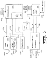
- the apparatus comprises a microcontroller 1006, digital logic 1010, a first analog-to-digital (A/D) convener 28, a read out amplifier 1014, a temperature sensing apparatus 1030, a dither pick-off apparatus 1024, and a dither drive 1002.
- the microcontroller 1006 may comprise any of a number of conventional microcontrollers such as the Intel 80C196KC microcontroller manufactured by Intel Corporation, USA.
- the microcontroller 1006 advantageously has an on board analogue to digital convener 304.
- the dither drive 1002 receives a dither drive signal 1004 to drive a dither motor on the ring laser gyro (not shown) in a conventional manner through drive line 23.
- a dither pick-off signal 22 is received from the drive elements, in this example received from piezo-electrical elements (PZTs). The use of PZT elements on ring laser gyro dither motors is well known.
- the dither pick-off signal 22 is amplified through an amplifier 24 in the dither pick-off apparatus 1024 and the dither pick-off signal is then provided by the dither pick-off apparatus on lines 306 and line 26.
- Line 306 is connected to a first input of the second A/D converter 304.
- Line 26 is connected to an input of the first A/D converter 28.
- the temperature sensor 1030 outputs a temperature signal on line 1032 which is also received at a second input of the second A/D converter.
- Read out counts from the ring laser gyro are received from detector A on line 1020 and detector B on line 1022.
- the read out amplifier provides A and B channels 1016, 1018 respectively with an amplified count signal on each line to the digital logic 1010.
- Digital logic 1010 is also coupled at an interface bus 29 to the first A/D converter 28 in order to receive digitized dither pick-off signals.
- the digital logic is also coupled by means of bus 1012 to the microcontroller for purposes of transmitting data and addresses in a conventional manner.
- a sample request line 390 handles external system sample requests for gyro output data.
- the sample request line 390 operates as an interrupt to provide the requested data.
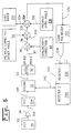
- the digital logic 1010 comprises an integrated circuit manufactured by "ACTEL, model number A1225". A more detailed description of the digital logic 1010 is shown in Figure 3. Those skilled in the art will recognize that other components may be added to the microcontroller shown herein for the purposes of adding more features to a modular ring laser gyro system.
- the digital logic 1010 comprises A/D control logic 348, a first latch 362, a second latch 368, a multiplexer 350 and address decoder 354, an up/down count logic 376 and up/down counter 374.
- Line 29 from the first A/D converter 28 further comprises an A/D serial data line 378, a chip select line 380 and a system clock line 382.
- the A/D control logic 348 also receives the sample request line 390 as generated by an external request for data.
- A/D control logic 348 receives dither pick-off information on A/D serial data line 378.
- the A/D control logic 348 ten processes the A/D serial data 378 to provide a value for the dither angle a on line 356 to the multiplexer 350.
- Up/down count logic 376 receives readout A from the ring laser gyro on channel 1016 and readout B from the ring laser gyro on channel 1018. Up/down count logic 376 processes the read out information in a well known manner and passes it to the up/down counter 374. Data from up/down counter 374 is provided to latch 362 and latch 368. The first latch 362 is enabled via control line 394 from the microcontroller 1006 at each peak and zero crossing of the dither signal as shown in Figure 1. The second latch 368 is enabled by an enable signal on control line 360 in response to an external request impressed on sample request line 390.
- the second latch 368 When the second latch 368 is enabled it latches the counter output 366 as ring laser gyro count angle ⁇ which is transmitted on line 370 to the multiplexer 350.
- the address decoder switches multiplexer 350 by means of a control signal on line 355 to switch either the dither angle ⁇ , gyro angle ⁇ or gyro angle ⁇ through the multiplexer 350 onto the bus 1012.
- the ring laser gyro count angles ⁇ and ⁇ may comprise the same value. That is, they both comprise unstripped gyro angle counts. However, the angle ⁇ is latched only at times substantially simultaneous with peaks and zero crossings of the dither pickoff signal as discussed above with reference to Figure 1. In contrast, the angle ⁇ is equivalent to gyro count data taken at the time an external system request is processed. An external system request may occur at any time. Further, the angle ⁇ may be provided to the external system as a corrected angle by applying the previous correction factors in a manner similar to that discussed herein for internal use for deriving a stripped gyro angle output.
- FIG. 4 a schematic block diagram of a method and apparatus for calculation of a change in stripped gyro output angle ⁇ g is implied in one example of the present invention as shown.
- the piezo-electric (PZT) or other dither drive element 20 provides a dither signal 22 to an amplifier 24 which outputs an amplified dither signal on line 26 into first A/D convener 28.
- the first A/D converter 28 converts the analog signal received on line 26 into a digital data signal on line 30 which is provided to a gain element 32 labeled DSGAIN.
- the output of DSGAIN gain element 32 on line 34 is a dither angle ⁇ .
- the dither angle ⁇ on line 34 is summed at a first summing junction 36 with phase corrections from phase correction apparatus 40 which are provided on line 41.
- the output of the first summing junction 36 on line 42 is provided to a second summing junction 44 where it is subtracted from a nonlinearity correction factor as provided by nonlinearity correction apparatus 84 on line 86.
- the second summing junction 44 then provides a corrected signal on line 46 to a third summing junction 47 where it is subtracted from the previous dither angle provided in a conventional way by storage device 50.
- the difference is then output on line 52 to a fourth summing junction 58 where it is summed to the previous gyro angle stored in memory element 53 and subtracted from the current gyro angle which may be stored in memory device 54.
- the output of the fourth summing junction is transmitted on line 60 to a fifth summing junction 61 where it is added to bias and thermal bias terms K 1 , K 2 , and K 3 along with a current bias term K 1 from block 76.
- K 1 may be determined from factory calibration measurements.
- the output is provided on line 63 to a sixth summing junction 66 where it is added to thermal count K 4 , K 5 , and K 6 .
- the output of the sixth summing junction 66 is added at a seventh summing junction 70 with a scale factor correction provided by block 82 on line 80 to provide the final stripped gyro angle ⁇ g in this example.
- PZT 20 is read at each system request in less than one microsecond and is within 0.16 microseconds of the gyro count reading.
- the PZT voltage value is corrected for the gain of the amplifier and the PZT; corrected for the pick-off amplitude nonlinearity; corrected for the phase difference between the pick-off and the gyro; and subtracted from the previous corrected pick-off angle.
- This value is then subtracted from the difference in the previous unstripped gyro angle and the present unstripped gyro angle. This produces the change in stripped gyro angle.
- This value is then further corrected by the gyro bias and count calibrations as a function of temperature. At this time the gyro scale factor is also corrected.
- the dither stripping and related calculations described throughout this specification may be accomplished with reference to the stripped or unstripped gyro angle itself without using the change in stripped gyro angle.
- This alternate approach eliminates the need for subtracting previous dither angle and previous gyro angle values since all angles are accumulated to provide a count representing the gyro angle output.
- the stripped gyro angle may also be expressed as the sum of all of the changes in stripped gyro angles.
- the corrections and adjustments to the gyro and dither counts may be done at a resolution of at least 1.0 counts, but may be much smaller, that is, resolutions as low as 0.1 counts may be used. Those skilled in the art will also recognize that the terms may be summed in any order.
- the output 22 of PZT 20 is read by the A/D converters.
- the second A/D converter is under microcontroller control and is read to control the dither amplitude; to measure the dither stripper gain; to measure the mean value of the PZT amplifier output; and to find the phase angle error.
- the PZT amplifier voltage is also read by the first A/D 28 upon command from an external system request. Compensation of the PZT measurement is made by multiplying the PZT voltage by the DSGAIN value measured in the DSGAIN loop and corrected for phase and nonlinearity.
- the nonlinearity correction is a constant. It is stored in a memory device, as, for example an EEPROM 1007.
- the value of 5000 is only an example and may vary as, for example, with temperature.
- the correction is for positive nonlinearity, i.e. if the measured angle is too large requiring this correction to be subtracted from the measured value thus reducing the measured value.
- Other nonlinearity equations may be used such as substituting a cubic equation for the quadratic.
- the phase error correction apparatus 40 between the pickoff voltage and the gyro angle may be derived by a measurement of a phase error angle at the gyro dither angle position.
- the phase error at other angles corresponding to external system request times may advantageously be found through a look up table which comprises values for a predetermined error correction function, as, for example, a cosine or sine function, expressed as a percentage of the peak dither angle.
- the phase loop as shown in Figure 6 determines the phase error counts at both positive going and negative going zero crossings.
- the resultant value is called MAXPHASE and it is a signed value.
- MAXPHASE phase angle on the dither cycle.
- ALPHAMAX maximum command dither angle
- the sine of the phase angle on the dither cycle may be determined.
- the phase correction may then be determined as the cosine of the dither cycle phase angle multiplied by MAXPHASE.
- a simple look up table which references a cosine value for corresponding sine values may be employed to look up the phase correction.
- the value of this correction may be added to the output angle in increments of 0.1 counts and any residual angle of 0.001 counts retained as DELTAR. This preserves the accuracy of about ⁇ 0.001 deg/hour to the gyro.
- TMP the value of the present filtered temperature
- TMPP the previous temperature
- the value of this correction may be added to the output angle in increments of 0.1 counts and any residual angle of 0.001 counts retrained as DELTART. This preserves the accuracy of 0.001 deg/hour. Note that each count is 1.1123 arc seconds and that 1 count/second is 1.112 deg/hour. The maximum value of these terms, for one embodiment of a modular laser gyro is about 2 arc seconds per 2°F. Therefore, at thermal rates of even 300°F per hour, this term is not greater that 0.12 counts per second.
- the correction of scale factor 82 may be corrected to an accuracy of one part per million.
- the total output angle may be monitored and a correction of counts be performed whenever the total equals or exceeds a pre-stored signed value. This correction may be accomplished at each output request when the output DELTAR is greater than a predetermined number of counts; for example, 1,000 counts. Residuals must be retained to preserve the scale factor accuracy of 1 ppm. This value will change about 4 ppm as the mode changes.
- the dither stripper gain is calculated by a function based upon the dither drive values at each peak.
- the DSGAIN may be used to correct the PZT measured voltage to be a substantially exact measure of the dither angle as expressed in counts.
- the DSGAIN has the dimensions of gyro counts/volt.
- the gain has a time constant of 0.2 seconds for the first 3 seconds after starting the RLG system and 12 seconds thereafter.
- the calculation for dither stripper gain may be processed as follows. At each dither peak, such as when the dither output is measured for the dither drive loop. PZT 20 outputs a signal on line 22 which is amplified by amplifier 24. The amplified PZT signal is output onto line 306 and received by A/D converter 304 which supplies a digital signal representative of the PZT output on line 308. The unstripped gyro angle is then used, together with the previous value of the unstripped gyro angle and a correction for nonlinearity 84 from stored parameters, to find a value for the gain correction factor DSGAIN. The value of the PZT output on line 308 is multiplied by the gain element 32 labeled DSGAIN.
- the resultant output from the gain element 32 is output as a gain corrected dither angle on line 310 and received by a scaling element 312.
- the scaling element 312 operates to scale the dither angle. In one example of the invention, the scaling element 312 operates to divide the gain corrected dither angle on line 310 by a factor of 10000.
- a nonlinearity correction 84 is then added to the scaled dither angle at summing junction 316.
- Summing junction 316 outputs the nonlinearity corrected dither signal on line 318 which is received by a second summing junction 320. Note that the nonlinearity correction does not have to be recalculated each time because the nonlinearity correction is always the same at the peak dither angle which is equal to the command angle. This value for the nonlinearity correction may be read from stored parameters.
- the output of the second summing junction is a difference value which is sent on line 328 to a third summing junction 329.
- a block 331 stores the previous unstripped gyro angle and a block 322 stores the current unstripped gyro angle.
- the current unstripped gyro angle is impressed on line 324 and subtracted from the difference value on line 328 while the previous gyro angle is impressed on line 326 and summed at the third summing junction to the difference value on line 328.
- the resulting value is impressed on line 330 and gain multiplier 332 operates on the result.
- gain multiplier 332 multiplies the result from line 330 by a gain of 600 for the first second after start of the RLG and by 10 thereafter to produce a gain correction value. In this way, the multiplier 332 operates to adjust the time constant in the gain correction loop.
- the gain correction value is then accumulated in a 32 bit register 335.
- Register 335 is comprised of low 16 bit register 336 and high 16 bit register 340. The most significant bits, register 340, are used to correct the DSGAIN factor. In this way the gain factor, DSGAIN, applied to the dither angle is continuously updated.
- FIG. 6 a functional diagram of one example of a method and apparatus for measuring a phase error angle as employed in the present invention is shown.
- the apparatus of Figure 6 includes PZT 20, amplifier 24, A/D 304, gain element 32 and scaling element 312 as discussed herein with reference to Figure 5.
- the aforesaid elements operate in a substantially similar manner as discussed above.
- a scaled dither angle is transmitted on line 414 to a first summing junction 416 which outputs a difference value to a second summing junction 420 which also receives a value representing the previous dither angle from storage device 50.
- the second summing junction provides a second difference on line 422 to a third summing junction 425.
- the third summing junction 425 also receives a value representing the unstripped gyro angle at the zero crossing from block 430 and the previous unstripped gyro angle at the zero crossing from block 434.
- the unstripped gyro angle at the zero crossing is subtracted and the previous unstripped gyro angle at the zero crossing is added to the second difference value to yield a corrected angle on line 436.
- the corrected angle is then multiplied by a factor from a phase angle gain multiplier element 438 to produce an error angle count at zero crossings on line 440.
- the output is switched as a positive or negative value into a register 445.
- Register 442 holds the low 16 bits and register 444 holds the high 16 bits of 32 bit register 445.
- the sign of the switch 451 follows the sign of the zero crossing dither angle as explained hereinbelow.
- the phase correction is made from the phase error measured by the phase error loop of Figure 6.
- the output stripped angle is measured and is added to a 32 bit accumulator with a sign set at plus for the zero crossing and negative for the 180° crossing.
- the output of this accumulator is added to the PZT count output also with the sign of the crossing.
- This loop finds the value of counts which satisfy the loop, and is the measure of the phase error angle. This value is used in the dither stripper to correct a gyro angle output in response to a system request.
- the compensation of the laser gyro output is accomplished by compensation for three sets of nominal constants.
- the constants include:
- the coefficients K 1 , K 2 , and K 3 may each be handled as a 16 bit number and all calculations may be performed to preserve an accuracy of at least 2 x 10 -4 deg/hour.
- K' coefficients have values which are corrected for a scale factor (SF) and in one embodiment of the invention may be as shown in Table II below: Coefficient Calculation Maximum Value @ 200°F Minimum Value of Correction @ 200°F (1/2 of LSB) Q Value Per Least Sig.
- steps may advantageously be processed in background software programs since they do not depend on current gyro data with the exception of temperature which is filtered through a one second filter.
- the calculation may advantageously be done once per second so that in one hour this calculation may be performed 3600 times.
- Coefficients for correcting angle error as a function of temperature may be determined from gyro thermal tests for each gyro. Typical coefficients are expressed as shown below in Table III. Coefficient Dimension Typical Value Value at 200°F and 360°F/hour rate K 4 deg/°F -0.35 x 10 -3 -0.126 deg/hour K 5 deg/°F/°F 0.17 x 10 -5 0.122 deg/hour
- the K 4 and K 5 coefficients may each be handled as a 16 bit number and all calculations may be performed to an accuracy of at least 2 x 10 -4 deg/hour when exposed to an input thermal rate of 360°F/hour and at 200°F.
- the data stored in the microcontroller may advantageously be stored for 16 bit calculations to preserve accuracy.
- the values of K' coefficients which are corrected for a scale factor (SF) are as shown below in Table IV.
- ⁇ -764 counts per second (assuming the temperature rate is 0.02° per second). This equates to a count of one every 86 seconds or 0.012° per hour at 100°F. Note that at 0°F, the correction is 0.023° per hour.
- a difference in temperature of 0.1°F produces an angle correction of about 0.05 counts. Therefore, this term, even at thermal rates of 360°F/hour, produces a correction of only 0.05 counts per second.
- a measurement of once per 10 seconds will keep the corrections to less than 1 count even in the presence of very high thermal rates of up to 700°F/hour.
- a measurement of once per second permits high resolution calculations at up to 7,000°F per hour.
- the scale factor correction may be accomplished to an accuracy of about one ppm by using a number N to make corrections.
- This value, N is equal to the number of counts which are counted before making a correction of one count.
- N is used in the microprocessor to correct the scale factor by adding or subtracting a count, as appropriate, every time the output increases or decreases by N counts.
- the non-corrected gyro counts are 11,631,120. In that angle, the above correction will add 19,985 counts for a total of 11,651,105 counts which is the equivalent of 1.3 ppm error. This correction of about 0.2% is at the maximum range of performance by an RLG.
- the nominal scale factor is 1.11234 arc seconds per count.
- the peak error is 0.5 ppm.
- the RMS error is equal to the peak error divided by 3 1/2 .
- the RMS error is 0.29 ppm.
- the RMS error is 1.15 ppm.
Landscapes
- Physics & Mathematics (AREA)
- Engineering & Computer Science (AREA)
- Optics & Photonics (AREA)
- Electromagnetism (AREA)
- Power Engineering (AREA)
- General Physics & Mathematics (AREA)
- Radar, Positioning & Navigation (AREA)
- Remote Sensing (AREA)
- Gyroscopes (AREA)
Claims (13)
- Procédé de détermination d'une variation pure d'un angle de gyroscope comprenant les étapes consistant à:(a) détecter une pluralité d'amplitudes de crête P1, P2, P3 ...Pn, à partir d'un signal d'attaque d'activation dans lequel chaque amplitude de la pluralité des amplitudes de crête présente des instants correspondants t1, t2, t3 ... tn, et(b) détecter simultanément une pluralité d'angles de sortie de gyroscope à laser en anneau à chacun des instants correspondants t1, t2, t3 ... tn, et(c) déterminer une variation pure d'angle de gyroscope Δ, en fonction d'une relation selon laquelle
- Procédé selon la revendication 1, comprenant l'étape consistant à ajouter des valeurs de Δ avec le signe de αn dans un intégrateur afin de corriger la valeur de K.
- Procédé selon la revendication 2, dans lequel l'étape consistant à ajouter des valeurs de Δ avec le signe de αn dans un intégrateur pour corriger la valeur de K comprend en outre les étapes consistant à:(a) augmenter l'angle d'activation du facteur de correction, K, afin d'obtenir un angle d'activation corrigé,(b) prendre la différence entre un angle d'activation corrigé précédent et l'angle d'activation corrigé afin d'obtenir une variation d'angle d'activation, et(c) prendre la différence entre un angle de gyroscope actuel et la variation de l'angle d'activation et combiner un angle de gyroscope précédent afin d'obtenir une modification du facteur de correction K.
- Procédé selon la revendication 3, comprenant l'étape consistant à augmenter la variation du facteur de correction K d'un second facteur de gain afin d'obtenir une modification de facteur de correction mise à jour.
- Dispositif séparateur de signal d'activation destiné à un gyroscope à laser en anneau comprenant : un moyen destiné à détecter les amplitudes de crête et les instants correspondants d'un détecteur d'angle d'activation de gyroscope à laser en anneau (22), dans lequel le détecteur d'angle d'activation (22) comporte une sortie de détecteur d'angle d'activation (26, 306), la sortie de détecteur d'angle d'activation (26, 306) comprend une pluralité de passages par zéro et de crêtes, le dispositif séparateur de signal d'activation comprenant :un moyen de commande (1006) destiné à obtenir un signal d'angle de gyroscope pur, et comportant une sortie de commande (1004) qui est activée pour attaquer le moteur d'activation du gyroscope à laser en anneau,un premier moyen de conversion analogique vers numérique (28) destiné à convertir la sortie de détecteur d'angle d'activation (26) en une première sortie de détecteur d'angle d'activation numérique (29), dans lequel le premier moyen de conversion analogique vers numérique (28) est relié à la sortie de détecteur d'angle d'activation (26), etun second moyen de conversion analogique vers numérique (304) destiné à convertir la sortie de détecteur d'angle d'activation (306) en une seconde sortie de détecteur d'angle d'activation numérique (308).
- Dispositif selon la revendication 5, dans lequel le dispositif séparateur de signal d'activation comprend en outre un moyen logique de comptage/décomptage (376) comportant une sortie de compteur (364, 366),un moyen logique destiné à une commande analogique vers numérique (348) comportant une entrée reliée de façon à recevoir la première sortie de détecteur d'angle d'activation numérique (29, 378), une sortie de validation de demande d'échantillonnage (360) et une sortie d'angle d'activation (356), dans lequel la sortie de validation de demande d'échantillonnage est sensible à une demande d'échantillonnage externe (390),un premier moyen de circuit à verrouillage (362) destiné à mémoriser un comptage, comportant une entrée de validation reliée à une sortie de commande (394) du moyen de commande (1006), dans lequel le premier moyen de circuit à verrouillage (362) comporte une sortie (372) de premier circuit à verrouillage, le comptage représentant un angle de détection de gyroscope à laser,un second moyen de circuit à verrouillage (368) destiné à mémoriser le comptage, comportant une enliée de validation reliée à la sortie (360) de validation de demande d'échantillonnage, dans lequel le second moyen de circuit à verrouillage (368) comporte une sortie (370) de second circuit à verrouillage , etun moyen de multiplexeur (350) destiné à appliquer un signal de données d'angle sur un bus de données (1012) en réponse à un signal de demande d'adresses de bus (355) comportant une première entrée de multiplexeur reliée à la sortie d'angle d'activation (356), une seconde entrée de multiplexeur reliée à la sortie (372) du premier circuit à verrouillage, et une troisième entrée de multiplexeur reliée à la sortie (370) du second circuit à verrouillage.
- Dispositif selon la revendication 5 ou 6, comprenant en outre un moyen destiné à générer un facteur de gain de séparateur d'activation destiné à être utilisé dans un gyroscope à laser en anneau, le moyen de génération comprenant:un moyen (20) destiné à appliquer un signal d'activation sur une sortie de signal d'activation (22),un moyen destiné à amplifier (24) relié, au niveau d'une enliée, à la sortie de signal d'activation (22), le moyen d'amplification (24) comportant une sortie amplifiée (306),un moyen destiné à une conversion analogique vers numérique (304) comportant une entrée reliée de façon à recevoir la sortie amplifiée (306) et comportant une sortie numérique qui fournit un signal numérique représentatif de la sortie amplifiée (308),un moyen (32) destiné à additionner un gain, comportant une première enliée reliée à la sortie numérique (308) et comportant une sortie de gain (310), le moyen d'addition de gain agissant de façon à multiplier une valeur de la sortie numérique par un facteur de gain, dans lequel le moyen destiné à additionner un gain (32) comporte également une enliée de facteur de gain (342),un moyen de mise à l'échelle (312) comportant une entrée reliée la sortie de gain (310) et comportant une sortie d'angle d'activation (314),un moyen destiné à appliquer une correction de non-linéarité (84), relié à la sortie d'angle d'activation (314), comportant une sortie (318) d'angle d'activation corrigé de la non-linéarité,un premier moyen destiné à soustraire un angle d'activation précédent de la sortie d'angle (320) d'activation corrigé de la non-linéarité, le premier moyen destiné à soustraire comprenant une entrée reliée de façon à recevoir la sortie d'angle (318) d'activation corrigé de la non-linéarité et comportant une première sortie de valeur de différence (328),un second moyen destiné à soustraire un angle de gyroscope actuel et à additionner un angle de gyroscope précédent (329), le second moyen de soustraction comprenant une entrée reliée à la première sortie de valeur de différence (328) et comportant une seconde sortie de valeur de différence (330),un moyen de multiplicateur de gain destiné à multiplier (332) comportant une entrée reliée à la seconde sortie de valeur de différence (330) et comportant une sortie commutée (334) dans lequel le moyen de multiplicateur de gain (332) multiplie la seconde sortie de valeur de différence (330) afin de produire un facteur de correction de gain au niveau d'un commutateur de sortie de facteur de correction de gain (334) dans lequel une polarité du facteur de correction de gain est commutée pour suivre la polarité de la sortie d'angle d'activation (314), etun moyen (335) relié au commutateur de sortie de facteur de correction de gain (334), destiné à transférer le facteur de correction de gain vers le moyen destiné à additionner un gain grâce à une liaison vers l'entrée de facteur de gain (342).
- Dispositif selon la revendication 7, dans lequel le moyen de transfert (335) comprend en outre un moyen de registre (336, 340) relié au niveau d'une entrée de données au commutateur de sortie de facteur de correction de gain (334), le moyen de registre comprenant une sortie de données reliée à l'entrée de facteur de gain (342).
- Dispositif selon l'une quelconque des revendications 7 ou 8, dans lequel le moyen de multiplicateur de gain (332) multiplie par un premier facteur de gain pendant un premier intervalle de temps après le démarrage d'un gyroscope à laser en anneau et par un second facteur de gain ensuite afin de produire un facteur de correction de gain (334).
- Dispositif selon l'une quelconque des revendications 5 à 9, comprenant en outre:un moyen destiné à fournir un signal d'activation (20) sur une sortie de signal d'activation (22),un moyen destiné à amplifier (24) relié, au niveau d'une entrée, à la sortie de signal d'activation (22), le moyen d'amplification comportant une sortie amplifiée (306),un moyen destiné à une conversion analogique vers numérique (304) comportant une entrée reliée de façon à recevoir la sortie amplifiée (306) et comportant une sortie numérique qui fournit un signal numérique représentatif de la sortie amplifiée (308),un moyen destiné à additionner un gain (32) comportant une première entrée reliée à la sortie numérique (308) et comportant une sortie de gain (310), le moyen d'addition de gain (32) agissant de façon à multiplier une valeur de la sortie numérique (308) par un facteur de gain,un moyen destiné à une mise à l'échelle (312) comportant une entrée reliée à la sortie de gain (310) et comportant une sortie d'angle d'activation (414),un moyen destiné à fournir une correction d'angle d'erreur (416) relié à la sortie d'angle d'activation (414) comportant une sortie d'angle d'activation corrigé de l'angle d'erreur et comportant une entrée de correction d'angle d'erreur (450),un moyen (420) destiné à soustraire un angle d'activation précédent de la sortie d'angle d'activation corrigé de l'angle d'erreur, le moyen destiné à soustraire (420) comprenant une entrée reliée de façon à recevoir la sortie d'angle d'activation corrigé de l'angle d'erreur et comportant une sortie de valeur de différence (422),un moyen (425) destiné à soustraire un angle de gyroscope actuel et à additionner un angle de gyroscope précédent, le moyen de soustraction et d'addition (425) comprenant une entrée reliée à la sortie de valeur de différence (422) et comportant une sortie de sommation (436),un moyen de multiplicateur de gain destiné à multiplier (438), comportant une entrée reliée à la sortie de sommation (436) et comportant une sortie commutée, dans lequel le moyen de multiplicateur de gain multiplie la valeur de différence afin de produire un angle d'erreur de phase au niveau d'un commutateur de sortie (440), dans lequel une polarité de l'angle d'erreur de phase est commutée pour suivre une polarité de la sortie d'angle d'activation (414), etun moyen (445) relié au commutateur de sortie (440), destiné à transférer l'angle d'erreur de phase vers le moyen (416) destiné à fournir une correction d'angle d'erreur.
- Dispositif selon la revendication 10, comprenant en outre :un moyen de registre (444, 442) comportant une entrée de données reliée au commutateur de sortie (440), le premier moyen de registre comportant également une sortie de données (446), etun commutateur polarisé (451) comportant une entrée reliée de façon à recevoir la sortie de données (446) et comportant une sortie reliée à l'entrée de correction d'angle d'erreur (450), dans lequel le commutateur polarisé commute un signe de polarité de la correction d'angle d'erreur de phase (446) pour suivre la sortie de signal d'activation (22).
- Dispositif selon l'une quelconque des revendications 5 à 11, dans lequel le moyen de commande (1006) comprend un microprocesseur.
- Dispositif selon l'une quelconque des revendications 5 à 12, dans lequel le second moyen de conversion analogique vers numérique (304) est incorporé dans le microprocesseur.
Applications Claiming Priority (3)
| Application Number | Priority Date | Filing Date | Title |
|---|---|---|---|
| US137669 | 1987-12-24 | ||
| US08/137,669 US5486920A (en) | 1993-10-01 | 1993-10-01 | Laser gyro dither strippr gain correction method and apparatus |
| PCT/US1994/011180 WO1995010025A1 (fr) | 1993-10-01 | 1994-09-30 | Suppresseur de signaux d'activation pour gyroscope laser annulaire active |
Publications (2)
| Publication Number | Publication Date |
|---|---|
| EP0704048A1 EP0704048A1 (fr) | 1996-04-03 |
| EP0704048B1 true EP0704048B1 (fr) | 2000-02-09 |
Family
ID=22478529
Family Applications (1)
| Application Number | Title | Priority Date | Filing Date |
|---|---|---|---|
| EP94930554A Expired - Lifetime EP0704048B1 (fr) | 1993-10-01 | 1994-09-30 | Suppresseur de signaux d'activation pour gyroscope laser annulaire active |
Country Status (5)
| Country | Link |
|---|---|
| US (1) | US5486920A (fr) |
| EP (1) | EP0704048B1 (fr) |
| CA (1) | CA2166801A1 (fr) |
| DE (1) | DE69422985T2 (fr) |
| WO (1) | WO1995010025A1 (fr) |
Families Citing this family (59)
| Publication number | Priority date | Publication date | Assignee | Title |
|---|---|---|---|---|
| US7206646B2 (en) | 1999-02-22 | 2007-04-17 | Fisher-Rosemount Systems, Inc. | Method and apparatus for performing a function in a plant using process performance monitoring with process equipment monitoring and control |
| US8044793B2 (en) * | 2001-03-01 | 2011-10-25 | Fisher-Rosemount Systems, Inc. | Integrated device alerts in a process control system |
| US6975219B2 (en) * | 2001-03-01 | 2005-12-13 | Fisher-Rosemount Systems, Inc. | Enhanced hart device alerts in a process control system |
| US7562135B2 (en) | 2000-05-23 | 2009-07-14 | Fisher-Rosemount Systems, Inc. | Enhanced fieldbus device alerts in a process control system |
| US6354964B1 (en) | 1999-12-06 | 2002-03-12 | Honeywell Inc. | Single beam signal blanking for enhanced path length control in a ring laser gyro |
| US6795798B2 (en) | 2001-03-01 | 2004-09-21 | Fisher-Rosemount Systems, Inc. | Remote analysis of process control plant data |
| US7389204B2 (en) * | 2001-03-01 | 2008-06-17 | Fisher-Rosemount Systems, Inc. | Data presentation system for abnormal situation prevention in a process plant |
| US8073967B2 (en) | 2002-04-15 | 2011-12-06 | Fisher-Rosemount Systems, Inc. | Web services-based communications for use with process control systems |
| EP1364263B1 (fr) | 2001-03-01 | 2005-10-26 | Fisher-Rosemount Systems, Inc. | Partage de donnees dans une installation de traitement |
| US7720727B2 (en) * | 2001-03-01 | 2010-05-18 | Fisher-Rosemount Systems, Inc. | Economic calculations in process control system |
| US6813532B2 (en) * | 2001-03-01 | 2004-11-02 | Fisher-Rosemount Systems, Inc. | Creation and display of indices within a process plant |
| US6954713B2 (en) * | 2001-03-01 | 2005-10-11 | Fisher-Rosemount Systems, Inc. | Cavitation detection in a process plant |
| US20020191102A1 (en) * | 2001-05-31 | 2002-12-19 | Casio Computer Co., Ltd. | Light emitting device, camera with light emitting device, and image pickup method |
| US6476918B1 (en) | 2001-06-21 | 2002-11-05 | Honeywell International Inc. | Dither control system for a ring laser gyro |
| US7162534B2 (en) * | 2001-07-10 | 2007-01-09 | Fisher-Rosemount Systems, Inc. | Transactional data communications for process control systems |
| US6704111B2 (en) | 2001-09-11 | 2004-03-09 | Honeywell International Inc. | High temperature electrode seal in a ring laser gyro |
| US7600234B2 (en) * | 2002-12-10 | 2009-10-06 | Fisher-Rosemount Systems, Inc. | Method for launching applications |
| US8935298B2 (en) | 2002-12-30 | 2015-01-13 | Fisher-Rosemount Systems, Inc. | Integrated navigational tree importation and generation in a process plant |
| US7493310B2 (en) | 2002-12-30 | 2009-02-17 | Fisher-Rosemount Systems, Inc. | Data visualization within an integrated asset data system for a process plant |
| US7152072B2 (en) | 2003-01-08 | 2006-12-19 | Fisher-Rosemount Systems Inc. | Methods and apparatus for importing device data into a database system used in a process plant |
| US20040158474A1 (en) * | 2003-02-06 | 2004-08-12 | Karschnia Robert J. | Service facility for providing remote diagnostic and maintenance services to a process plant |
| US7953842B2 (en) | 2003-02-19 | 2011-05-31 | Fisher-Rosemount Systems, Inc. | Open network-based data acquisition, aggregation and optimization for use with process control systems |
| US7103427B2 (en) | 2003-02-28 | 2006-09-05 | Fisher-Rosemont Systems, Inc. | Delivery of process plant notifications |
| US6915235B2 (en) * | 2003-03-13 | 2005-07-05 | Csi Technology, Inc. | Generation of data indicative of machine operational condition |
| US7634384B2 (en) * | 2003-03-18 | 2009-12-15 | Fisher-Rosemount Systems, Inc. | Asset optimization reporting in a process plant |
| US20040230328A1 (en) * | 2003-03-21 | 2004-11-18 | Steve Armstrong | Remote data visualization within an asset data system for a process plant |
| US7088452B2 (en) * | 2003-04-11 | 2006-08-08 | Honeywell International Inc. | Dither stripper with non-linearity correction |
| US7299415B2 (en) * | 2003-06-16 | 2007-11-20 | Fisher-Rosemount Systems, Inc. | Method and apparatus for providing help information in multiple formats |
| US7030747B2 (en) * | 2004-02-26 | 2006-04-18 | Fisher-Rosemount Systems, Inc. | Method and system for integrated alarms in a process control system |
| US7079984B2 (en) * | 2004-03-03 | 2006-07-18 | Fisher-Rosemount Systems, Inc. | Abnormal situation prevention in a process plant |
| US7676287B2 (en) * | 2004-03-03 | 2010-03-09 | Fisher-Rosemount Systems, Inc. | Configuration system and method for abnormal situation prevention in a process plant |
| US7515977B2 (en) * | 2004-03-30 | 2009-04-07 | Fisher-Rosemount Systems, Inc. | Integrated configuration system for use in a process plant |
| US20050267709A1 (en) * | 2004-05-28 | 2005-12-01 | Fisher-Rosemount Systems, Inc. | System and method for detecting an abnormal situation associated with a heater |
| US7536274B2 (en) * | 2004-05-28 | 2009-05-19 | Fisher-Rosemount Systems, Inc. | System and method for detecting an abnormal situation associated with a heater |
| WO2005124491A1 (fr) | 2004-06-12 | 2005-12-29 | Fisher-Rosemount Systems, Inc. | Systeme et methode de detection d'une situation anormale associee a un gain de process d'une boucle de controle |
| US7181654B2 (en) * | 2004-09-17 | 2007-02-20 | Fisher-Rosemount Systems, Inc. | System and method for detecting an abnormal situation associated with a reactor |
| US8005647B2 (en) | 2005-04-08 | 2011-08-23 | Rosemount, Inc. | Method and apparatus for monitoring and performing corrective measures in a process plant using monitoring data with corrective measures data |
| US9201420B2 (en) | 2005-04-08 | 2015-12-01 | Rosemount, Inc. | Method and apparatus for performing a function in a process plant using monitoring data with criticality evaluation data |
| US7440109B1 (en) * | 2006-06-28 | 2008-10-21 | The United States Of America As Represented By The Secretary Of The Navy | Dither stripper having least-mean-squares adaptive updating of dither stripper gains |
| US7912676B2 (en) * | 2006-07-25 | 2011-03-22 | Fisher-Rosemount Systems, Inc. | Method and system for detecting abnormal operation in a process plant |
| US7657399B2 (en) * | 2006-07-25 | 2010-02-02 | Fisher-Rosemount Systems, Inc. | Methods and systems for detecting deviation of a process variable from expected values |
| US8145358B2 (en) * | 2006-07-25 | 2012-03-27 | Fisher-Rosemount Systems, Inc. | Method and system for detecting abnormal operation of a level regulatory control loop |
| US8606544B2 (en) | 2006-07-25 | 2013-12-10 | Fisher-Rosemount Systems, Inc. | Methods and systems for detecting deviation of a process variable from expected values |
| JP5197610B2 (ja) * | 2006-09-28 | 2013-05-15 | フィッシャー−ローズマウント システムズ,インコーポレイテッド | 熱交換器における異常状態の防止 |
| US8489360B2 (en) * | 2006-09-29 | 2013-07-16 | Fisher-Rosemount Systems, Inc. | Multivariate monitoring and diagnostics of process variable data |
| US20080188972A1 (en) * | 2006-10-11 | 2008-08-07 | Fisher-Rosemount Systems, Inc. | Method and System for Detecting Faults in a Process Plant |
| US8032340B2 (en) | 2007-01-04 | 2011-10-04 | Fisher-Rosemount Systems, Inc. | Method and system for modeling a process variable in a process plant |
| US8032341B2 (en) * | 2007-01-04 | 2011-10-04 | Fisher-Rosemount Systems, Inc. | Modeling a process using a composite model comprising a plurality of regression models |
| US7827006B2 (en) * | 2007-01-31 | 2010-11-02 | Fisher-Rosemount Systems, Inc. | Heat exchanger fouling detection |
| US10410145B2 (en) * | 2007-05-15 | 2019-09-10 | Fisher-Rosemount Systems, Inc. | Automatic maintenance estimation in a plant environment |
| US8301676B2 (en) * | 2007-08-23 | 2012-10-30 | Fisher-Rosemount Systems, Inc. | Field device with capability of calculating digital filter coefficients |
| US7702401B2 (en) | 2007-09-05 | 2010-04-20 | Fisher-Rosemount Systems, Inc. | System for preserving and displaying process control data associated with an abnormal situation |
| US9323247B2 (en) | 2007-09-14 | 2016-04-26 | Fisher-Rosemount Systems, Inc. | Personalized plant asset data representation and search system |
| US8055479B2 (en) | 2007-10-10 | 2011-11-08 | Fisher-Rosemount Systems, Inc. | Simplified algorithm for abnormal situation prevention in load following applications including plugged line diagnostics in a dynamic process |
| US9927788B2 (en) | 2011-05-19 | 2018-03-27 | Fisher-Rosemount Systems, Inc. | Software lockout coordination between a process control system and an asset management system |
| US8905635B2 (en) | 2011-09-30 | 2014-12-09 | Honeywell International Inc. | Temperature sensor attachment facilitating thermal conductivity to a measurement point and insulation from a surrounding environment |
| US8901432B2 (en) | 2011-09-30 | 2014-12-02 | Honeywell International Inc. | Mitigation of block bending in a ring laser gyroscope caused by thermal expansion or compression of a circuit board |
| US9529348B2 (en) | 2012-01-24 | 2016-12-27 | Emerson Process Management Power & Water Solutions, Inc. | Method and apparatus for deploying industrial plant simulators using cloud computing technologies |
| CN110926449B (zh) * | 2019-12-17 | 2023-04-11 | 重庆华渝电气集团有限公司 | 一种提高触发式光纤陀螺标度因数线性度的方法 |
Family Cites Families (10)
| Publication number | Priority date | Publication date | Assignee | Title |
|---|---|---|---|---|
| US3373650A (en) * | 1965-04-02 | 1968-03-19 | Honeywell Inc | Laser angular rate sensor |
| US4248534A (en) * | 1979-05-09 | 1981-02-03 | The Singer Company | Apparatus and method for the elimination of angular vibration induced errors in ring laser gyroscopes |
| US4344706A (en) * | 1980-07-14 | 1982-08-17 | The Singer Company | Ring laser gyro dither pulse eliminator |
| US4529311A (en) * | 1981-07-06 | 1985-07-16 | Honeywell Inc. | Ring laser gyro system |
| US4610543A (en) * | 1985-04-03 | 1986-09-09 | The Singer Company | Electronic dither compensator for a ring laser gyro |
| US4751718A (en) * | 1985-05-10 | 1988-06-14 | Honeywell Inc. | Dither suspension mechanism for a ring laser angular rate sensor |
| US4802766A (en) * | 1986-12-23 | 1989-02-07 | Honeywell Inc. | Dither signal remover for a dithered ring laser angular rate sensor |
| US5048963A (en) * | 1989-11-01 | 1991-09-17 | Honeywell Inc. | Dither signal remover for a dithered ring laser gyro |
| US5225889A (en) * | 1991-12-11 | 1993-07-06 | Fritze Keith R | Laser gyro dither drive |
| US5249031A (en) * | 1991-12-11 | 1993-09-28 | Honeywell Inc. | Ring laser gyro dither stripper |
-
1993
- 1993-10-01 US US08/137,669 patent/US5486920A/en not_active Expired - Lifetime
-
1994
- 1994-09-30 DE DE69422985T patent/DE69422985T2/de not_active Expired - Lifetime
- 1994-09-30 WO PCT/US1994/011180 patent/WO1995010025A1/fr not_active Ceased
- 1994-09-30 EP EP94930554A patent/EP0704048B1/fr not_active Expired - Lifetime
- 1994-09-30 CA CA002166801A patent/CA2166801A1/fr not_active Abandoned
Also Published As
| Publication number | Publication date |
|---|---|
| CA2166801A1 (fr) | 1995-04-13 |
| EP0704048A1 (fr) | 1996-04-03 |
| DE69422985T2 (de) | 2000-06-29 |
| US5486920A (en) | 1996-01-23 |
| DE69422985D1 (de) | 2000-03-16 |
| WO1995010025A1 (fr) | 1995-04-13 |
Similar Documents
| Publication | Publication Date | Title |
|---|---|---|
| EP0704048B1 (fr) | Suppresseur de signaux d'activation pour gyroscope laser annulaire active | |
| AU699978B2 (en) | Modular laser gyro | |
| US5444639A (en) | Angular rate sensing system and method, with digital synthesizer and variable-frequency oscillator | |
| EP1341311A2 (fr) | Dispositif de traitement de signaux pour un codeur | |
| EP0642216A1 (fr) | Filtre suiveur et générateur de référence de quadrature de phase | |
| EP0183838A1 (fr) | Systeme de reference d'inertie | |
| US5893054A (en) | Amplitude detection and automatic gain control of a sparsely sampled sinusoid by computation including a hilbert transform | |
| KR100523650B1 (ko) | 진동회전센서전자장치내정량화잡음을줄이기위한제어방법및그장치 | |
| US4712427A (en) | Vibrating beam accelerometer with velocity change output | |
| US5048963A (en) | Dither signal remover for a dithered ring laser gyro | |
| US5249031A (en) | Ring laser gyro dither stripper | |
| US4802766A (en) | Dither signal remover for a dithered ring laser angular rate sensor | |
| EP0692160B1 (fr) | Convertisseur analogique/numerique a integration a correction de temperature | |
| HK1008081B (en) | Dither signal remover for a dithered ring laser gyro | |
| US5331402A (en) | Dither signal remover for a dithered ring laser angular rate sensor utilizing an adaptive digital filter | |
| US7088452B2 (en) | Dither stripper with non-linearity correction | |
| US12031821B2 (en) | Compensating a temperature-dependent quadrature-induced zero rate offset for a microelectromechanical gyroscope | |
| US5329355A (en) | Dither stripper to leave base motion | |
| JPH11344339A (ja) | 電子磁気コンパス | |
| US4888705A (en) | System for measuring the position of vibrating object | |
| JP4287975B2 (ja) | 姿勢計測装置 | |
| EP0690972B1 (fr) | Appareil de suppression du signal d'activation d'un gyrolaser | |
| HK47490A (en) | Vibrating beam accelerometer with velocity change output | |
| WO1987002467A1 (fr) | Accelerateur a regle vibrante avec sortie de changement de vitesse |
Legal Events
| Date | Code | Title | Description |
|---|---|---|---|
| PUAI | Public reference made under article 153(3) epc to a published international application that has entered the european phase |
Free format text: ORIGINAL CODE: 0009012 |
|
| 17P | Request for examination filed |
Effective date: 19951214 |
|
| AK | Designated contracting states |
Kind code of ref document: A1 Designated state(s): DE FR GB SE |
|
| 17Q | First examination report despatched |
Effective date: 19970505 |
|
| GRAG | Despatch of communication of intention to grant |
Free format text: ORIGINAL CODE: EPIDOS AGRA |
|
| GRAG | Despatch of communication of intention to grant |
Free format text: ORIGINAL CODE: EPIDOS AGRA |
|
| GRAG | Despatch of communication of intention to grant |
Free format text: ORIGINAL CODE: EPIDOS AGRA |
|
| GRAH | Despatch of communication of intention to grant a patent |
Free format text: ORIGINAL CODE: EPIDOS IGRA |
|
| GRAG | Despatch of communication of intention to grant |
Free format text: ORIGINAL CODE: EPIDOS AGRA |
|
| GRAH | Despatch of communication of intention to grant a patent |
Free format text: ORIGINAL CODE: EPIDOS IGRA |
|
| GRAA | (expected) grant |
Free format text: ORIGINAL CODE: 0009210 |
|
| AK | Designated contracting states |
Kind code of ref document: B1 Designated state(s): DE FR GB SE |
|
| ET | Fr: translation filed | ||
| REF | Corresponds to: |
Ref document number: 69422985 Country of ref document: DE Date of ref document: 20000316 |
|
| PLBE | No opposition filed within time limit |
Free format text: ORIGINAL CODE: 0009261 |
|
| STAA | Information on the status of an ep patent application or granted ep patent |
Free format text: STATUS: NO OPPOSITION FILED WITHIN TIME LIMIT |
|
| 26N | No opposition filed | ||
| REG | Reference to a national code |
Ref country code: GB Ref legal event code: IF02 |
|
| PGFP | Annual fee paid to national office [announced via postgrant information from national office to epo] |
Ref country code: SE Payment date: 20050905 Year of fee payment: 12 |
|
| PG25 | Lapsed in a contracting state [announced via postgrant information from national office to epo] |
Ref country code: SE Free format text: LAPSE BECAUSE OF NON-PAYMENT OF DUE FEES Effective date: 20061001 |
|
| EUG | Se: european patent has lapsed | ||
| PGFP | Annual fee paid to national office [announced via postgrant information from national office to epo] |
Ref country code: GB Payment date: 20090807 Year of fee payment: 16 |
|
| PGFP | Annual fee paid to national office [announced via postgrant information from national office to epo] |
Ref country code: DE Payment date: 20090930 Year of fee payment: 16 |
|
| GBPC | Gb: european patent ceased through non-payment of renewal fee |
Effective date: 20100930 |
|
| REG | Reference to a national code |
Ref country code: DE Ref legal event code: R119 Ref document number: 69422985 Country of ref document: DE Effective date: 20110401 |
|
| PG25 | Lapsed in a contracting state [announced via postgrant information from national office to epo] |
Ref country code: DE Free format text: LAPSE BECAUSE OF NON-PAYMENT OF DUE FEES Effective date: 20110401 |
|
| PG25 | Lapsed in a contracting state [announced via postgrant information from national office to epo] |
Ref country code: GB Free format text: LAPSE BECAUSE OF NON-PAYMENT OF DUE FEES Effective date: 20100930 |
|
| PGFP | Annual fee paid to national office [announced via postgrant information from national office to epo] |
Ref country code: FR Payment date: 20130826 Year of fee payment: 20 |
|
| P01 | Opt-out of the competence of the unified patent court (upc) registered |
Effective date: 20230525 |