EP0704255A2 - Dispositif d'inversion de la direction de transport d'envois plats - Google Patents
Dispositif d'inversion de la direction de transport d'envois plats Download PDFInfo
- Publication number
- EP0704255A2 EP0704255A2 EP95113897A EP95113897A EP0704255A2 EP 0704255 A2 EP0704255 A2 EP 0704255A2 EP 95113897 A EP95113897 A EP 95113897A EP 95113897 A EP95113897 A EP 95113897A EP 0704255 A2 EP0704255 A2 EP 0704255A2
- Authority
- EP
- European Patent Office
- Prior art keywords
- transport
- fence
- conveying means
- transport roller
- fence elements
- Prior art date
- Legal status (The legal status is an assumption and is not a legal conclusion. Google has not performed a legal analysis and makes no representation as to the accuracy of the status listed.)
- Granted
Links
- 238000007599 discharging Methods 0.000 claims description 6
- 238000000034 method Methods 0.000 claims description 5
- 238000001514 detection method Methods 0.000 description 3
- 238000010586 diagram Methods 0.000 description 3
- 230000007423 decrease Effects 0.000 description 1
- 230000007257 malfunction Effects 0.000 description 1
- 239000013049 sediment Substances 0.000 description 1
- 230000002123 temporal effect Effects 0.000 description 1
Images



Classifications
-
- B—PERFORMING OPERATIONS; TRANSPORTING
- B07—SEPARATING SOLIDS FROM SOLIDS; SORTING
- B07C—POSTAL SORTING; SORTING INDIVIDUAL ARTICLES, OR BULK MATERIAL FIT TO BE SORTED PIECE-MEAL, e.g. BY PICKING
- B07C1/00—Measures preceding sorting according to destination
- B07C1/20—Sorting according to orientation, e.g. according to position of stamp
-
- B—PERFORMING OPERATIONS; TRANSPORTING
- B65—CONVEYING; PACKING; STORING; HANDLING THIN OR FILAMENTARY MATERIAL
- B65H—HANDLING THIN OR FILAMENTARY MATERIAL, e.g. SHEETS, WEBS, CABLES
- B65H15/00—Overturning articles
- B65H15/016—Overturning articles employing rotary or reciprocating elements supporting transport means
-
- B—PERFORMING OPERATIONS; TRANSPORTING
- B65—CONVEYING; PACKING; STORING; HANDLING THIN OR FILAMENTARY MATERIAL
- B65H—HANDLING THIN OR FILAMENTARY MATERIAL, e.g. SHEETS, WEBS, CABLES
- B65H2701/00—Handled material; Storage means
- B65H2701/10—Handled articles or webs
- B65H2701/19—Specific article or web
- B65H2701/1916—Envelopes and articles of mail
Definitions
- the present invention relates to a device for reversing the transport direction of flat mail items for mail distribution systems.
- mail distribution systems in which flat mail items are supplied with character recognition and marking devices in order to distribute the mail items in accordance with various information applied to their surface, there is a problem in that a part of the mail items is transported in the conveying means in such a way that the information provided Surface is not arranged in the processing position opposite the character recognition and identification means.
- a shipment that is not in the processing position can be brought into the working position by rotating the shipment about the longitudinal axis and / or the vertical axis.
- a problem that arises with such rotations is that the gaps between the consignments or the distances between the front or rear edges of the consignment are changed by the operation of the rotation, possibly even overlapping of consignments, which can lead to blockages and malfunction of the system.
- a device for reversing the direction of flat mail items is already known from DE 43 15 053, with conveying means for feeding the mail items at a first speed and further funding means for removing the mail items at a second speed, the first conveying means for feeding the mail items at a first predetermined speed in the second funding for receiving the Consignments and detection means for determining the point in time at which the rear edge of a consignment that has left the first conveying means is provided.
- Each shipment is picked up in the second conveyor at the first predetermined speed and, as soon as its rear edge has left the first conveyor, braked according to a predetermined speed profile. The direction of conveyance is then reversed and the shipment is accelerated to a second predetermined speed.
- Third funding is provided for receiving the mail items from the second funding at the second predetermined speed, the sediments in the first, second and third funding being guided non-positively at all times.
- the object of the present invention is to provide a device with which mail items can be rotated quickly and safely about their vertical axis.
- the object of the features of independent claims 1 and 2 is achieved, advantageous embodiments of the invention are contained in the subclaims and the description. It is particularly advantageous in the device according to the invention that the consignments are guided smoothly and safely within the device.
- the programs always remain recorded and are never left to their own devices. This achieves a high degree of precision in the movement of the mail items and prevents mail run disruptions.
- This device brakes and accelerates the mail gently.
- the device is also particularly space-saving.
- the mail items are rotated in such a way that the gaps in the mail flow before and after the mail items are rotated are the same, or not the mail item gaps, but the distances between the front or rear edges of the items before and after the rotation remain constant.
- the mail items 3a are first transferred from the feeding conveying means 1 to the device for reversing.
- the conveying means 1 usually consist of conveyor belts, between which the items are moved upright.
- the reversing device essentially has two fence elements 4, 5 arranged symmetrically to one another, between which a transport roller 3 is arranged.
- the transport roller and the fence elements are arranged in an area between the conveying means 1 and the discharging conveying means 2 so as to be rotatable about an axis A.
- the fence elements 4, 5 are arranged essentially parallel to one another and tangential to the transport roller. Each fence element forms an essentially linearly elongated and angled sliding surface for the mail items.
- the two fence elements are point symmetrical to each other arranged to the axis of rotation A that together they form a transport channel, the cross section of which decreases in the region of the angled part of each fence element.
- Transport roller 3 and fence elements 4, 5 can be rotated about the same axis A.
- Each fence element consists of a section with a bend and a section which is substantially linear. Seen from the common axis A of the transport roller and fence element, the angled section of each fence element extends less far than the linear section of the respectively opposite fence element.
- the linear section of a fence element serves as a receiving surface for the mail items during the supply and as a removal area during the removal of the mail items. For this purpose, it is advantageous that this part protrudes into the area of the feeding or discharging conveying means when the mail items are picked up or removed in such a way that secure pick up or removal of the mail item is ensured.
- the end region of this section preferably projects above the conveyor belts 1a and 2a.
- the fastening of all rollers and conveyor belts projecting into the radius of the fence elements 4, 5 is designed such that no collisions with the fence elements 4, 5 occur.
- each fence element is used to transfer mail items for which no reversal of the transport direction is provided to the conveying means 2 at undiminished speed. From the angled section of each fence element, such a continuous mail is directed against the linear section of the opposite fence element, from which it is slidably transferred to the conveying means 2.
- the transport roller 3 is arranged between the two fence elements 4 and 5 such that a flat consignment can be guided non-positively between the transport roller 3 and a fence element 4, 5.
- This essentially requires the selection of a suitable distance between the transport roller and the fence element as well as resilient sliding surfaces 7 in the area of each fence element in which the mail items between the fence element and the transport roller are non-positively guided.
- the shipment is transported by the transport roller 3 to the discharging conveying means 2 at an undiminished speed.
- the transport roller 3 is operated at a speed that is adapted to the feed speed of the mail items.
- the letter transported between the transport roller 3 and the fence 4 is thereby moved from the linearly elongated part of the fence 4 to the angled area and directed in the direction of the opposite linear section of the fence 5.
- the fence elements rotate through 180 ° around the axis A.
- the rotation begins at the earliest as soon as the rear edge of the shipment has left the conveying means 1 and this has been determined by detection means not shown in FIG. 1. While this 180 ° rotation is carried out, the speed of the transport roller is negated.
- the consignment is then moved by the transport roller along the linearly elongated part of the fence 4 and, after completion of the rotation, is transferred to the conveying means 2 smoothly. As soon as the shipment loses contact with the transport roller 3, the latter becomes Reverse speed again to be ready for the recording of the next program.
- the contact between the shipment and the transport roller is monitored by detection means not shown in FIG. 1.
- the following consignment may already have left the funding 1 in part, that is, protrude into the swivel range of the fence elements when the 180 ° rotation has been completed. This enables a reduction in the smallest safely processable shipment gap.
- C denotes a possible trajectory of the rear edge of the consignment during the turning process.
- the deviation from a circular path around the axis A results from the movement of the item between the fence element 4 and the transport roller 3 that is carried out during the rotary movement.
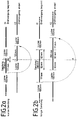
- FIG. 2 illustrates the dynamic processes that typically occur when the device is operated.
- the device can process mail items of different lengths. Shipment lengths between 135 mm and 295 mm are assumed as an example; the gaps between the continuously fed items are, for example, 100 mm each at a feed speed of 3 m / s.
- Figure 2b shows the case of a long shipment. At time t1, the rotation is initiated, which in turn lasts 37 ms.
- the two representations 2a and 2b show that, in the example under consideration, t2 must be selected such that at this point in time the left edge of the letter is 111 mm further away from the axis of rotation A than the right. This way from 111 mm corresponds to a rotation time of 37 ms at 3 m / s.
- t 180 l min - l klem, min V , where V denotes the transport speed and l min the length of the shortest letter to be processed.
- l klem, min is the minimum clamping length required for secure contact between the transport roller and the consignment, cf. Figure 2a.
- FIG. 3 shows a sectional view along the length X-X in FIG. 1.
- the device is then mechanically driven by two electric motors 8, 9, which are arranged on the same geometric axis A.
- the torque of the motor 8 is passed on to the fence elements 4, 5 and to the transport roller 3 via a hollow shaft 10 which surrounds a shaft 11. It is advantageous to avoid unnecessary moments of inertia: the fence elements 4, 5 can be designed as a wire frame.
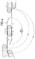
- FIG. 1 A further embodiment of the invention is shown in FIG.
- two rollers 12 and 13 are provided which can be rotated about an axis B.
- the rollers 12 and 13 are advantageously provided with an endless belt 14 in order to ensure better guidance of the item 3a.
- the letters are gripped earlier by one of the transport rollers 12, 13, so that the rotary movement can be started earlier and may take a long time. Therefore, with This arrangement advantageously extends the time available for a 180 ° rotation of the fence elements.
- the transport rollers 12, 13 are each independently rotatable about their axes of rotation 6, 6 'with respect to the rotational movement of the fence elements 4 and 5 about the common axis of rotation B.
- FIG. 5 shows a further embodiment of the mechanical drive for the device according to the invention.
- the torque of the motor 14 is then transmitted via the shaft 16 or the motor 15 via the drive belt 17 to the hollow shaft 18 to the transport roller or the fence elements.
- the shafts are supported in bearings 19.
Landscapes
- Engineering & Computer Science (AREA)
- Mechanical Engineering (AREA)
- Delivering By Means Of Belts And Rollers (AREA)
- Attitude Control For Articles On Conveyors (AREA)
- Registering Or Overturning Sheets (AREA)
- Sorting Of Articles (AREA)
- Separation, Sorting, Adjustment, Or Bending Of Sheets To Be Conveyed (AREA)
- Manufacturing And Processing Devices For Dough (AREA)
Applications Claiming Priority (2)
| Application Number | Priority Date | Filing Date | Title |
|---|---|---|---|
| DE4431800 | 1994-09-07 | ||
| DE4431800A DE4431800A1 (de) | 1994-09-07 | 1994-09-07 | Vorrichtung zur Umkehrung der Transportrichtung von flachen Sendungen |
Publications (3)
| Publication Number | Publication Date |
|---|---|
| EP0704255A2 true EP0704255A2 (fr) | 1996-04-03 |
| EP0704255A3 EP0704255A3 (fr) | 1998-01-21 |
| EP0704255B1 EP0704255B1 (fr) | 2001-08-16 |
Family
ID=6527592
Family Applications (1)
| Application Number | Title | Priority Date | Filing Date |
|---|---|---|---|
| EP95113897A Expired - Lifetime EP0704255B1 (fr) | 1994-09-07 | 1995-09-05 | Dispositif d'inversion de la direction de transport d'envois plats |
Country Status (3)
| Country | Link |
|---|---|
| EP (1) | EP0704255B1 (fr) |
| AT (1) | ATE204214T1 (fr) |
| DE (2) | DE4431800A1 (fr) |
Cited By (1)
| Publication number | Priority date | Publication date | Assignee | Title |
|---|---|---|---|---|
| EP1424299A3 (fr) * | 2002-11-27 | 2005-01-26 | Kabushiki Kaisha Toshiba | Dispositif de commande pour retourner des feuilles et procédé de commande |
Families Citing this family (1)
| Publication number | Priority date | Publication date | Assignee | Title |
|---|---|---|---|---|
| US9132979B1 (en) * | 2014-05-06 | 2015-09-15 | Xerox Corporation | Shuttling nip set for media sheet inversion |
Citations (1)
| Publication number | Priority date | Publication date | Assignee | Title |
|---|---|---|---|---|
| DE4315053A1 (de) | 1993-05-06 | 1994-11-10 | Licentia Gmbh | Vorrichtung zur Richtungsumkehr von flachen Sendungen |
Family Cites Families (12)
| Publication number | Priority date | Publication date | Assignee | Title |
|---|---|---|---|---|
| DD17547A (fr) * | ||||
| GB621533A (en) * | 1946-01-29 | 1949-04-11 | Milos Horica | A device for turning over articles of flat shape at a point where they are transferred from one conveyor belt to another conveyor belt |
| DE2153051A1 (de) * | 1971-10-25 | 1973-05-03 | Wilhelm Dr Ing May | Verfahren und vorrichtung zum ausrichten von briefen od.dgl. auf ihrem transportweg von einer aufgabestelle zu einer selbsttaetig arbeitenden sortiervorrichtung |
| FR2315131A1 (fr) * | 1975-06-19 | 1977-01-14 | Signaux Entr Electriques | Appareil de controle de titres de transport a piste magnetique |
| DE3412464A1 (de) * | 1984-04-03 | 1985-10-10 | Adrema Maschinenbau GmbH, 6148 Heppenheim | Vorrichtung zum wenden flacher gegenstaende, insbesondere befuellter briefumschlaege |
| DE8410361U1 (de) * | 1984-04-03 | 1987-09-10 | Adrema Maschinenbau GmbH, 6148 Heppenheim | Vorrichtung zum Wenden flacher Gegenstände, insbesondere befüllter Briefumschläge |
| DE3634860A1 (de) * | 1986-10-13 | 1988-04-14 | Microhandling Handhabungsgerae | Vorrichtung zum sortieren unter gleichzeitigem wenden (insichdrehen um 180(grad)) von quaderfoermigen bauteilen |
| US4798278A (en) * | 1987-07-23 | 1989-01-17 | General Machine Design, Inc. | Conveyor for turning packages upside down |
| GB2230245A (en) * | 1989-04-12 | 1990-10-17 | Noshe Eng Ltd | Article orientators |
| DE4107464A1 (de) * | 1991-03-08 | 1992-09-10 | Schmid Gmbh & Co Geb | Verfahren und vorrichtung zum einseitigen behandeln von plattenfoermigen gegenstaenden |
| JP3127035B2 (ja) * | 1992-01-31 | 2001-01-22 | 芝浦メカトロニクス株式会社 | 紙葉類反転さばき装置 |
| FR2695381B1 (fr) * | 1992-09-08 | 1994-11-04 | Sierem Sa | Dispositif de modification de l'orientation de produits présentant au moins deux faces tels des paquets d'articles. |
-
1994
- 1994-09-07 DE DE4431800A patent/DE4431800A1/de not_active Withdrawn
-
1995
- 1995-09-05 AT AT95113897T patent/ATE204214T1/de not_active IP Right Cessation
- 1995-09-05 DE DE59509507T patent/DE59509507D1/de not_active Expired - Fee Related
- 1995-09-05 EP EP95113897A patent/EP0704255B1/fr not_active Expired - Lifetime
Patent Citations (1)
| Publication number | Priority date | Publication date | Assignee | Title |
|---|---|---|---|---|
| DE4315053A1 (de) | 1993-05-06 | 1994-11-10 | Licentia Gmbh | Vorrichtung zur Richtungsumkehr von flachen Sendungen |
Cited By (3)
| Publication number | Priority date | Publication date | Assignee | Title |
|---|---|---|---|---|
| EP1424299A3 (fr) * | 2002-11-27 | 2005-01-26 | Kabushiki Kaisha Toshiba | Dispositif de commande pour retourner des feuilles et procédé de commande |
| US7080834B2 (en) | 2002-11-27 | 2006-07-25 | Kabushiki Kaisha Toshiba | Sheets reversing controller and control method |
| EP2236446A1 (fr) * | 2002-11-27 | 2010-10-06 | Kabushiki Kaisha Toshiba | Dispositif pour retourner des courriers et procédé de retour |
Also Published As
| Publication number | Publication date |
|---|---|
| EP0704255A3 (fr) | 1998-01-21 |
| ATE204214T1 (de) | 2001-09-15 |
| EP0704255B1 (fr) | 2001-08-16 |
| DE59509507D1 (de) | 2001-09-20 |
| DE4431800A1 (de) | 1996-03-14 |
Similar Documents
| Publication | Publication Date | Title |
|---|---|---|
| EP0827931B1 (fr) | Dispositif et méthode pour le guidage dynamique d'objets plats | |
| DE3718206A1 (de) | Vorrichtung zum foerdern und drehen von papierstapeln | |
| DE2643709A1 (de) | Sortiervorrichtung fuer ungeordnet verteiltes stueckgut | |
| DE3917115A1 (de) | Verfahren und vorrichtung zum aendern der relativstellung von packungen, insbesondere quaderfoermigen zigaretten-packungen des typs klappschachtel (hinge-lid-packung) | |
| DD211963A5 (de) | Vorrichtung zur sortierung laenglicher teile | |
| DE3315490A1 (de) | Verfahren und vorrichtung zum stapeln von druckbogen o.dgl. | |
| EP0727370B1 (fr) | Installation de transport | |
| DE69515772T2 (de) | Verfahren und vorrichtung zum überlappen von dokumenten | |
| EP0085418A2 (fr) | Procédé et installation pour appliquer des étiquettes auto-adhésives | |
| DE4315053C2 (de) | Vorrichtung zur Richtungsumkehr von flachen Sendungen | |
| DE2830197C2 (fr) | ||
| DE3743676C2 (de) | Druck- und/oder Prägevorrichtung | |
| DE69317117T2 (de) | Segmentierter transportabschnitt mit schneller laufenden entnahme-bändern | |
| EP0704255B1 (fr) | Dispositif d'inversion de la direction de transport d'envois plats | |
| DE102006033987A1 (de) | Zubringereinrichtung | |
| EP1753681A1 (fr) | Dispositif pour inverser le sens de marchandises plates | |
| DE10158426A1 (de) | Vorrichtung zum Sortieren von flächigen Stückgütern | |
| EP0775657A2 (fr) | Dispositif pour aligner des objets postaux plats | |
| DE19916196B4 (de) | Vorrichtung und Verfahren zum Sammeln von Blattgut | |
| AT526066B1 (de) | Holzlamellenhandlinganlage, sowie ein Verfahren zum Betreiben der Holzlamellenhandlinganlage | |
| DE102018214048A1 (de) | Absetzband für eine Palettiervorrichtung | |
| DE3730132A1 (de) | Blechtransportvorrichtung | |
| DE1142879B (de) | Anordnung zum Transportieren, Stapeln oder Zufuehren von duennen, flachen, knickgefaehrdeten Foerderstuecken | |
| DE4237056C2 (de) | Vorrichtung zum Erfassen von auf einem runden Objekt aufgebrachten Informationsträgern | |
| EP0557725B1 (fr) | Appareil d'enroulage de matériau flexible et plat |
Legal Events
| Date | Code | Title | Description |
|---|---|---|---|
| PUAI | Public reference made under article 153(3) epc to a published international application that has entered the european phase |
Free format text: ORIGINAL CODE: 0009012 |
|
| AK | Designated contracting states |
Kind code of ref document: A2 Designated state(s): AT BE CH DE DK ES FR GB GR IE IT LI LU NL PT SE |
|
| RAP1 | Party data changed (applicant data changed or rights of an application transferred) |
Owner name: SIEMENS AKTIENGESELLSCHAFT |
|
| PUAL | Search report despatched |
Free format text: ORIGINAL CODE: 0009013 |
|
| AK | Designated contracting states |
Kind code of ref document: A3 Designated state(s): AT BE CH DE DK ES FR GB GR IE IT LI LU NL PT SE |
|
| RHK1 | Main classification (correction) |
Ipc: B07C 1/20 |
|
| 17P | Request for examination filed |
Effective date: 19980220 |
|
| 17Q | First examination report despatched |
Effective date: 19991130 |
|
| GRAG | Despatch of communication of intention to grant |
Free format text: ORIGINAL CODE: EPIDOS AGRA |
|
| GRAG | Despatch of communication of intention to grant |
Free format text: ORIGINAL CODE: EPIDOS AGRA |
|
| GRAH | Despatch of communication of intention to grant a patent |
Free format text: ORIGINAL CODE: EPIDOS IGRA |
|
| GRAH | Despatch of communication of intention to grant a patent |
Free format text: ORIGINAL CODE: EPIDOS IGRA |
|
| GRAA | (expected) grant |
Free format text: ORIGINAL CODE: 0009210 |
|
| AK | Designated contracting states |
Kind code of ref document: B1 Designated state(s): AT BE CH DE DK ES FR GB GR IE IT LI LU NL PT SE |
|
| PG25 | Lapsed in a contracting state [announced via postgrant information from national office to epo] |
Ref country code: NL Free format text: LAPSE BECAUSE OF FAILURE TO SUBMIT A TRANSLATION OF THE DESCRIPTION OR TO PAY THE FEE WITHIN THE PRESCRIBED TIME-LIMIT Effective date: 20010816 Ref country code: IE Free format text: LAPSE BECAUSE OF FAILURE TO SUBMIT A TRANSLATION OF THE DESCRIPTION OR TO PAY THE FEE WITHIN THE PRESCRIBED TIME-LIMIT Effective date: 20010816 Ref country code: GR Free format text: LAPSE BECAUSE OF NON-PAYMENT OF DUE FEES Effective date: 20010816 Ref country code: GB Free format text: LAPSE BECAUSE OF FAILURE TO SUBMIT A TRANSLATION OF THE DESCRIPTION OR TO PAY THE FEE WITHIN THE PRESCRIBED TIME-LIMIT Effective date: 20010816 |
|
| REF | Corresponds to: |
Ref document number: 204214 Country of ref document: AT Date of ref document: 20010915 Kind code of ref document: T |
|
| REG | Reference to a national code |
Ref country code: CH Ref legal event code: EP |
|
| PG25 | Lapsed in a contracting state [announced via postgrant information from national office to epo] |
Ref country code: LU Free format text: LAPSE BECAUSE OF NON-PAYMENT OF DUE FEES Effective date: 20010905 Ref country code: AT Free format text: LAPSE BECAUSE OF NON-PAYMENT OF DUE FEES Effective date: 20010905 |
|
| REF | Corresponds to: |
Ref document number: 59509507 Country of ref document: DE Date of ref document: 20010920 |
|
| PGFP | Annual fee paid to national office [announced via postgrant information from national office to epo] |
Ref country code: FR Payment date: 20010928 Year of fee payment: 7 |
|
| PG25 | Lapsed in a contracting state [announced via postgrant information from national office to epo] |
Ref country code: LI Free format text: LAPSE BECAUSE OF NON-PAYMENT OF DUE FEES Effective date: 20010930 Ref country code: CH Free format text: LAPSE BECAUSE OF NON-PAYMENT OF DUE FEES Effective date: 20010930 Ref country code: BE Free format text: LAPSE BECAUSE OF NON-PAYMENT OF DUE FEES Effective date: 20010930 |
|
| REG | Reference to a national code |
Ref country code: IE Ref legal event code: FG4D Free format text: GERMAN |
|
| PG25 | Lapsed in a contracting state [announced via postgrant information from national office to epo] |
Ref country code: SE Free format text: LAPSE BECAUSE OF FAILURE TO SUBMIT A TRANSLATION OF THE DESCRIPTION OR TO PAY THE FEE WITHIN THE PRESCRIBED TIME-LIMIT Effective date: 20011116 Ref country code: PT Free format text: LAPSE BECAUSE OF FAILURE TO SUBMIT A TRANSLATION OF THE DESCRIPTION OR TO PAY THE FEE WITHIN THE PRESCRIBED TIME-LIMIT Effective date: 20011116 Ref country code: DK Free format text: LAPSE BECAUSE OF FAILURE TO SUBMIT A TRANSLATION OF THE DESCRIPTION OR TO PAY THE FEE WITHIN THE PRESCRIBED TIME-LIMIT Effective date: 20011116 |
|
| PGFP | Annual fee paid to national office [announced via postgrant information from national office to epo] |
Ref country code: DE Payment date: 20011119 Year of fee payment: 7 |
|
| ET | Fr: translation filed | ||
| NLV1 | Nl: lapsed or annulled due to failure to fulfill the requirements of art. 29p and 29m of the patents act | ||
| GBV | Gb: ep patent (uk) treated as always having been void in accordance with gb section 77(7)/1977 [no translation filed] |
Effective date: 20010816 |
|
| PG25 | Lapsed in a contracting state [announced via postgrant information from national office to epo] |
Ref country code: ES Free format text: LAPSE BECAUSE OF FAILURE TO SUBMIT A TRANSLATION OF THE DESCRIPTION OR TO PAY THE FEE WITHIN THE PRESCRIBED TIME-LIMIT Effective date: 20020228 |
|
| BERE | Be: lapsed |
Owner name: SIEMENS A.G. Effective date: 20010930 |
|
| REG | Reference to a national code |
Ref country code: CH Ref legal event code: PL |
|
| PLBE | No opposition filed within time limit |
Free format text: ORIGINAL CODE: 0009261 |
|
| STAA | Information on the status of an ep patent application or granted ep patent |
Free format text: STATUS: NO OPPOSITION FILED WITHIN TIME LIMIT |
|
| 26N | No opposition filed | ||
| PG25 | Lapsed in a contracting state [announced via postgrant information from national office to epo] |
Ref country code: DE Free format text: LAPSE BECAUSE OF NON-PAYMENT OF DUE FEES Effective date: 20030401 |
|
| PG25 | Lapsed in a contracting state [announced via postgrant information from national office to epo] |
Ref country code: FR Free format text: LAPSE BECAUSE OF NON-PAYMENT OF DUE FEES Effective date: 20030603 |
|
| REG | Reference to a national code |
Ref country code: FR Ref legal event code: ST |
|
| PG25 | Lapsed in a contracting state [announced via postgrant information from national office to epo] |
Ref country code: IT Free format text: LAPSE BECAUSE OF NON-PAYMENT OF DUE FEES;WARNING: LAPSES OF ITALIAN PATENTS WITH EFFECTIVE DATE BEFORE 2007 MAY HAVE OCCURRED AT ANY TIME BEFORE 2007. THE CORRECT EFFECTIVE DATE MAY BE DIFFERENT FROM THE ONE RECORDED. Effective date: 20050905 |