EP0704276A2 - Mehrspindel-Drehbank - Google Patents
Mehrspindel-Drehbank Download PDFInfo
- Publication number
- EP0704276A2 EP0704276A2 EP95113375A EP95113375A EP0704276A2 EP 0704276 A2 EP0704276 A2 EP 0704276A2 EP 95113375 A EP95113375 A EP 95113375A EP 95113375 A EP95113375 A EP 95113375A EP 0704276 A2 EP0704276 A2 EP 0704276A2
- Authority
- EP
- European Patent Office
- Prior art keywords
- spindle
- spindle carrier
- carrier
- bearings
- bearing
- Prior art date
- Legal status (The legal status is an assumption and is not a legal conclusion. Google has not performed a legal analysis and makes no representation as to the accuracy of the status listed.)
- Withdrawn
Links
Images





Classifications
-
- B—PERFORMING OPERATIONS; TRANSPORTING
- B23—MACHINE TOOLS; METAL-WORKING NOT OTHERWISE PROVIDED FOR
- B23Q—DETAILS, COMPONENTS, OR ACCESSORIES FOR MACHINE TOOLS, e.g. ARRANGEMENTS FOR COPYING OR CONTROLLING; MACHINE TOOLS IN GENERAL CHARACTERISED BY THE CONSTRUCTION OF PARTICULAR DETAILS OR COMPONENTS; COMBINATIONS OR ASSOCIATIONS OF METAL-WORKING MACHINES, NOT DIRECTED TO A PARTICULAR RESULT
- B23Q39/00—Metal-working machines incorporating a plurality of sub-assemblies, each capable of performing a metal-working operation
- B23Q39/04—Metal-working machines incorporating a plurality of sub-assemblies, each capable of performing a metal-working operation the sub-assemblies being arranged to operate simultaneously at different stations, e.g. with an annular work-table moved in steps
- B23Q39/042—Metal-working machines incorporating a plurality of sub-assemblies, each capable of performing a metal-working operation the sub-assemblies being arranged to operate simultaneously at different stations, e.g. with an annular work-table moved in steps with circular arrangement of the sub-assemblies
- B23Q39/044—Metal-working machines incorporating a plurality of sub-assemblies, each capable of performing a metal-working operation the sub-assemblies being arranged to operate simultaneously at different stations, e.g. with an annular work-table moved in steps with circular arrangement of the sub-assemblies having at least one tool station cooperating with each work holder, e.g. multi-spindle lathes
-
- B—PERFORMING OPERATIONS; TRANSPORTING
- B23—MACHINE TOOLS; METAL-WORKING NOT OTHERWISE PROVIDED FOR
- B23Q—DETAILS, COMPONENTS, OR ACCESSORIES FOR MACHINE TOOLS, e.g. ARRANGEMENTS FOR COPYING OR CONTROLLING; MACHINE TOOLS IN GENERAL CHARACTERISED BY THE CONSTRUCTION OF PARTICULAR DETAILS OR COMPONENTS; COMBINATIONS OR ASSOCIATIONS OF METAL-WORKING MACHINES, NOT DIRECTED TO A PARTICULAR RESULT
- B23Q11/00—Accessories fitted to machine tools for keeping tools or parts of the machine in good working condition or for cooling work; Safety devices specially combined with or arranged in, or specially adapted for use in connection with, machine tools
- B23Q11/08—Protective coverings for parts of machine tools; Splash guards
- B23Q11/0883—Protective coverings for parts of machine tools; Splash guards for spindles, e.g. for their bearings or casings
-
- Y—GENERAL TAGGING OF NEW TECHNOLOGICAL DEVELOPMENTS; GENERAL TAGGING OF CROSS-SECTIONAL TECHNOLOGIES SPANNING OVER SEVERAL SECTIONS OF THE IPC; TECHNICAL SUBJECTS COVERED BY FORMER USPC CROSS-REFERENCE ART COLLECTIONS [XRACs] AND DIGESTS
- Y10—TECHNICAL SUBJECTS COVERED BY FORMER USPC
- Y10T—TECHNICAL SUBJECTS COVERED BY FORMER US CLASSIFICATION
- Y10T82/00—Turning
- Y10T82/25—Lathe
- Y10T82/2524—Multiple
-
- Y—GENERAL TAGGING OF NEW TECHNOLOGICAL DEVELOPMENTS; GENERAL TAGGING OF CROSS-SECTIONAL TECHNOLOGIES SPANNING OVER SEVERAL SECTIONS OF THE IPC; TECHNICAL SUBJECTS COVERED BY FORMER USPC CROSS-REFERENCE ART COLLECTIONS [XRACs] AND DIGESTS
- Y10—TECHNICAL SUBJECTS COVERED BY FORMER USPC
- Y10T—TECHNICAL SUBJECTS COVERED BY FORMER US CLASSIFICATION
- Y10T82/00—Turning
- Y10T82/25—Lathe
- Y10T82/2552—Headstock
- Y10T82/2562—Spindle and bearings
-
- Y—GENERAL TAGGING OF NEW TECHNOLOGICAL DEVELOPMENTS; GENERAL TAGGING OF CROSS-SECTIONAL TECHNOLOGIES SPANNING OVER SEVERAL SECTIONS OF THE IPC; TECHNICAL SUBJECTS COVERED BY FORMER USPC CROSS-REFERENCE ART COLLECTIONS [XRACs] AND DIGESTS
- Y10—TECHNICAL SUBJECTS COVERED BY FORMER USPC
- Y10T—TECHNICAL SUBJECTS COVERED BY FORMER US CLASSIFICATION
- Y10T82/00—Turning
- Y10T82/30—Miscellaneous
Definitions
- the present invention relates to a multiple spindle bar machine and, more particularly, to an improved spindle carrier and spindle carrier bearing design.
- a multiple spindle bar machine includes a spaced apart array of four, six or eight rotatable workpiece holding spindles mounted in a spindle carrier.
- the spindle carrier is supported in a headstock and is intermittently rotated or indexed a fraction of a full turn.
- Each spindle includes a collet at one end of the spindle adjacent a machining work zone for releasably securing a piece of bar stock.
- a predetermined length of the bar stock extends from an end of each spindle, defining a workpiece.
- cutting tools mounted on tool slides, engage workpieces at the machining work zone to perform machining operations.
- Each spindle is rotated at the same angular velocity by a spindle drive shaft which extends from a gearbox housing through an aperture in the spindle carrier coincident with the spindle carrier's axis of rotation or central axis.
- the gearbox housing is spaced apart from the headstock and supports a motor and associated sets of gears for rotating the spindle drive shaft at a desired angular velocity and rotating a main drum shaft.
- the main drum shaft drives an indexing mechanism which rotates or indexes the spindle carrier.
- the main drum shaft also drives sets of cams which move the tool slides and other cams which advance bar stock through its corresponding spindle to define a new workpiece.
- Each spindle, and therefore each workpiece, moves in steps about the central axis of the spindle carrier as the spindle carrier indexes.
- a spindle completes one orbit or a 360 degree rotation every six steps or indexes of the spindle carrier, that is, each index rotates the spindle carrier 60°.
- a spindle carrier indexes, a spindle moves in an arcuate path about the spindle drive shaft and the workpiece held by that spindle moves through successive spindle indexing positions within the machining work zone.
- the tool slides include a hexagonal end slide, having a tool mounting surface corresponding to each spindle carrier indexing position and a plurality of cross slides, one cross slide per spindle carrier indexing position.
- a six spindle machine has six indexing positions and six cross slides.
- the end slide and six cross slides whose movement is controlled by the main drum shaft in conjunction with sets of cams, move from starting locations removed from the machining work zones toward the workpieces.
- Tools mounted on the end and cross slides engage the workpieces at their current spindle indexing positions to perform the machining operations. After the longest cycle machining operation is complete, the end and cross slides retract to their starting locations and the spindle carrier is indexed to the next spindle carrier indexing position.
- Sufficient clearance is provided between the tool slide starting locations and the workpieces so that the workpieces do not impact the tools when the spindle carrier indexes to its next position.
- Tools mounted on the end slide engage the workpiece in a direction parallel to the central axis, that is, parallel to the spindle drive shaft, of the spindle carrier while tools mounted on the cross slides engage the workpieces in a direction perpendicular to the spindle carrier central axis.
- a bar stock pusher moves the bar stock along an axial dimension at a first spindle carrier indexing position.
- the spindle collet at that position opens and the predetermined length of bar stock is fed through the spindle to move a section of new unfinished bar to the machining work zone thereby defining a new workpiece.
- the spindle collet then closes to secure the new workpiece in position for subsequent machining operations.
- various machining operations are performed on the rotating workpiece.
- a cut-off tool mounted on a cross slide engages and severs the completed workpiece from the remaining bar stock.
- the spindle Upon the next index of the spindle carrier, the spindle returns to the first indexing position and the bar feeding, machining and cut-off sequence is repeated. Performing simultaneous machining operations on four, six or eight spaced apart rotating workpieces provides significant economies of scale in the high volume manufacture of parts as compared to single spindle machines wherein only one workpiece at a time is machined.
- the spindle carrier is rotatably supported in a bore in the headstock by two spaced apart roller bearing assemblies.
- the two spindle carrier roller bearings provided radial support to the spindle carrier, but did not provide axial support. That is, the spindle carrier was permitted to move axially within the headstock bore.
- Axial support for the spindle carrier was provided by a bearing coupled to the gearbox housing and a tubular spindle carrier stem overlying a portion of the spindle drive shaft, the carrier stem was coupled to the spindle carrier near one end of the carrier stem and rotatably journaled in the gearbox housing bearing at an opposite end of the carrier stem.
- the gearbox housing bearing provided both thrust and axial support to the carrier stem, that is, the bearing prevented both lateral and axial movement of the carrier stem. Since the spindle carrier was pinned to the carrier stem, axial movement of the spindle carrier was also constrained by the gearbox housing bearing.
- a multiple spindle bar machine constructed in accordance with the present invention includes a new and improved bearing structure for rotatably supporting a spindle carrier for indexed movement through multiple work orientations.
- a bar machine headstock includes first and second spaced apart uprights having a throughbore dimensioned to receive the spindle carrier.
- First and second sets of tapered roller bearings support the spindle carrier.
- a bearing loading plate applies a force to the first and second sets of roller bearings to minimize lateral movement of the bearings relative to the spaced apart uprights.
- the first and second sets of tapered roller bearings are circumferentially spaced around the outer surface of the spindle carrier. Each bearing in the first and second sets of bearings rotate about an axis transverse to an axis of rotation of the spindle carrier.
- the tapered bearings maintain a precise axial alignment and positional relationship between the spindle carrier and the cutting tools regardless of the thermal expansion of the bar machine components during operation thereby insuring accurate and consistent machining.
- the bar machine spindle carrier is supported by a base that also supports a drive system for simultaneously rotating multiple bars.
- the headstock is coupled to the base and maintained in a spaced relation to a gearbox also coupled to the base and housing a portion of the drive system.
- the spindle carrier supports a plurality of spaced apart rotatable bar holding spindles. Each spindle is coupled to a spindle drive gear and is journaled in a spindle bearing.
- the spindle carrier includes a throughbore aligned with a longitudinal axis of the spindle carrier and an interior manifold for routing pressurized fluid to preload each of the spindle bearings.
- a hollow spindle drive shaft extends through the spindle carrier throughbore and has a drive gear pinned to an end of the drive shaft. The drive gear intermeshes with each of the spindle drive gears providing uniform rotation of the spindles.
- a fluid coupling at an opposite end of the spindle drive shaft from the drive gear injects pressurized fluid into the drive shaft.
- a fluid coupling at the drive gear end of the drive shaft routes fluid from the drive shaft hollow cavity to the spindle carrier interior manifold.
- the fluid coupling at the drive gear end of the drive shaft includes a swivel connector coupled to the drive shaft and in fluid communication with the hollow cavity, a second connector coupled to the spindle carrier and in fluid communication with the spindle carrier manifold and a tube connected between the swivel connector and the second connector.
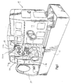
- Figure 1 is a perspective view of a multiple spindle bar machine 10 constructed in accordance with a preferred embodiment of the present invention.
- the bar machine 10 includes a cast base or pan 12 that collects metal chips produced during machining operations and serves as a sump for cooling fluids used to transmit heat away from a machining work zone 13 during operation of the bar machine 10.
- a gearbox housing 14 is coupled to and extends upwardly near one end of the pan 12.
- a headstock 16 also extending upwardly from and attached to the pan 12.
- a top plate 18 connects the gearbox housing 14 and the headstock 16 near a top portion of each. The top plate 18 ties the gearbox housing 14 and headstock 16 together and holds them firmly in alignment.
- a tailstock support 20 extends upwardly near an end of the pan 12 opposite the gearbox housing 14.
- the headstock 16 includes two uprights 22a, 22b having aligned throughbores 24a, 24b respectively.
- Upright 22a is closest to the headstock 16, while upright 22b is closest to the tailstock support 20.
- Only upright 22a and throughbore 24a can be seen in Figure 1, while in Figure 3, each can be seen in cross section.
- Rotatably supported in the upright throughbores 24a, 24b is a cylindrical spindle carrier 30.
- the carrier 30, supports six workpiece holding spindles 40a-40f in bores which are uniformly radially spaced through the carrier the carrier.
- the spindles 40a-40f and the workpieces (not shown) extending from the spindles into the machining work zone 13, are rotatably driven with respect to the spindle carrier 30 by a spindle drive shaft 50 which extends through a central aperture 52 in the spindle carrier 30.
- the spindle carrier central aperture 52 is coincident with the carrier's axis of rotation or central axis.
- the spindle drive shaft 50 is comprised of two sections 50a, 50b (best seen in Figure 3), the sections being press fit together. The first section 50a is supported within the gearbox housing 14, while the second section 50b extends from the gearbox housing 14 through the spindle carrier central aperture 52.
- a passageway 51 extends the length of the spindle drive shaft 50. Coupled to an end of the spindle drive shaft 50 extending through the spindle carrier central aperture 52 is a drive gear 54 (seen in Figures 3 and 4) which engages a set of six identical driven gears.
- Each of the driven gears is coupled to an outer periphery of a respective spindle 40a-40f. Only one of the driven gears 41a, which is coupled to spindle 40a, can be seen in Figure 3, while in Figure 4, all the driven gears 41a-41f, can be seen schematically.
- Rotation of the spindle drive shaft 50 causes rotation of the spindles 40a-40f (and workpieces supported thereby) at a uniform angular velocity.
- the spindle drive shaft 50 is rotatably supported within the spindle carrier central aperture 52 by a bearing 55 adjacent drive gear 54. Within the gearbox housing 14, the spindle drive shaft 50 is supported by bearings 56a, 56b.
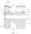
- a tubular spindle drive shaft carrier stem 57 Overlying a section of the spindle drive shaft 50 is a tubular spindle drive shaft carrier stem 57 (Figures 3 and 6).
- the carrier stem 57 is rotatably journaled at end one in a roller bearing 58 which is disposed in an opening in the gearbox housing 14 ( Figure 3) and pinned to the spindle carrier 30 adjacent the carrier's central aperture 52 by two spaced apart tapered pins 59a, 59b.
- the roller bearing 58 supports the carrier stem 57 radially, but does not provide significant thrust support, this is, it does not support the carrier stem 57 (nor the spindle carrier 30) in the axial direction.
- Axial support for the spindle carrier 30 and the carrier stem 57 is provided by two preloaded spindle carrier bearings 110,112, as will be described.
- Spindle drive shaft bearing 55 is axially secured in the spindle carrier central aperture 52 by a flange 60 overlying an outer ring or cup of the bearing.
- the flange 60 is secured by bolts 61 extending through apertures in the flange and threading into apertures in the spindle carrier 30.
- the flange 60 forces the cup of bearing 55 against an end of spindle carrier stem 57.
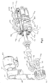
- the drive system includes a motor 62 having an output shaft 64 coupled to a drive pulley 66. Reeved over the drive pulley is a drive belt 68 which engages a driven pulley 70.
- the driven pulley 70 is fixed to a pulley shaft 72 having a gear 74 at one end. (Please note that all gears in Figure 2 are shown schematically for ease in depiction.)
- the pulley shaft gear 74 engages and rotates a spindle speed range gear 76 which, in turn, is coupled to a speed range gear shaft 78.
- a spindle speed change gear 80 which drives a drive gear 82 pinned to the spindle drive shaft 50.
- the spindle carrier 30 is rotated or indexed in fixed increments about the spindle drive shaft 50 by an indexing mechanism (not shown) of conventional design.
- the indexing mechanism includes a gear which engages a spindle carrier drive gear 84 to rotate the spindle carrier 30.
- the spindle carrier 30 is rotated one sixth of a complete revolution or 60° with each index thereby defining six indexing positions at which machining operations take place in the machining work zone 13.
- a given spindle, for example 40a, must increment six times to make a complete orbit about the spindle drive shaft 50.
- the indexing mechanism is driven by a main drum shaft (not shown).
- the tailstock support 20 includes an opening 90 (Figure 1) which rotatably supports a bar stock reel geared ring (not shown).
- the bar stock reel geared ring supports six spaced apart bar stock reel tubes (not shown) which are arrayed so as to be aligned with the spindles 40a-40f. Lengths of bar stock (not shown) are inserted into the reel tubes and are pushed forward to extend into each reel tube's corresponding aligned spindle.
- Each spindle 40a-40f includes a bar stock feeding apparatus of conventional design to feed out a predetermined length of bar stock from the spindle into the machining work area 13 at a specified first indexing position to define a new workpiece.
- the bar stock feeding apparatus includes a bar stock gripping collet 92 mounted in a nose 94 of the spindle 40a, a pusher tube 96 and collet actuating fingers 98 (one finger is seen in Figures 3 and 6).
- collet actuating fingers 98 spread apart, the collet 92 is moved forward in the spindle nose 94, that is, toward the machining work zone 13 and the collet opens.
- the stock feeding apparatus further includes a finger holder spool 100 slideably overlying the collet actuating fingers 98.
- An internal diameter of the finger holder spool 100 is such that in one spool position the collet actuating fingers 98 are closed up and in another position the collet actuating fingers are spread open.
- a pusher tube end flange 102 is coupled to an end of the pusher tube 96.
- Moving the collet 92 forward opens it to permit the advancing bar stock to move past the collet into the machining work zone 13.
- a bar stock stop (not shown) moves to a position in the machining work zone 13 in front of the spindle nose 94 to limit the advancement of the bar stock to a desired, predetermined amount.
- Advancement of the bar stock at the first indexing position defines a new workpiece.
- the workpiece will be machined at subsequent indexing positions as the spindle carrier 30 indexes in a counterclockwise orbit about the spindle drive shaft 50, that is, counterclockwise as the spindle carrier is viewed from the machining work zone 13.
- different machining operations are performed by tools (not shown) engaging the workpiece. Simultaneously, other tools engage and perform machining operations on workpieces at other spindle carrier indexing locations.
- Certain tools are mounted on an end tool slide (not shown), which moves parallel to a longitudinal axis of the workpiece (that is, parallel to the spindle drive shaft 50) and typically performs drilling operations.
- the end tool slide is slideably mounted on the spindle carrier stem 57 and is driven by the main drum shaft (not shown) in conjunction with a set of cams (not shown).
- a lubricating oil passageway 103 is provided through the wall of the spindle carrier stem 57. The oil introduced through passageway 103 forms a lubricating film in a gap between the overlying spindle carrier stem 57 and the spindle drive shaft 50 rotating within the carrier stem.
- cross slides (not shown) which are provided, one for each indexing position.
- the cross slides support tools which engage and machine a workpiece in a direction perpendicular to the longitudinal axis of the workpiece. Turning and threading are typical operations performed by tools mounted on cross slides.
- spindle 40d is at the final indexing position in Figure 2
- the completed workpiece is cut off from the bar stock and falls into a trough (not shown) which routes the completed workpiece to a parts basket (not shown).
- a rotational speed of the main drum shaft determines a travel speed of the end and cross slides.
- the drum shaft is rotated at a high speed (30 revolutions per minute) providing rapid movement of the end and cross slides.
- the power to drive the main drum shaft at the high rotational speed is taken from the pulley shaft 72 through a set of gears including gear 106 and a clutch assembly (not shown).
- the end and cross slides must travel at a much lower speed.
- the rotational speed of the drum shaft is reduced to between 1-15 rpm, depending on the material characteristics of the workpieces being machined. For example, if a hard material such as 316 stainless steel is being machined, a main drum shaft rotational speed as low as 1 rpm may be required while a rotational speed of up to 15 rpm may be suitable for a ductile material such as aluminum.
- the main drum shaft is driven at a desired low rotational speed by the spindle drive shaft 50 through a combination of gears, including gear 106 coupled to the spindle drive shaft, and a set of clutches (not shown).
- front and rear spindle carrier bearing assemblies 110, 112 at opposite ends of the spindle carrier 30 support the carrier for indexed rotation within the headstock upright throughbores 24a, 24b.
- Bearing geometry and preloading of the bearing assemblies 110, 112 contribute to accurate positioning of the spindle carrier 30 and insure its positional stability over a broad range of bar machine operating temperatures resulting in consistent, precise machining.
- the front spindle bearing assembly 110 is located near a front end 114 of the spindle carrier 30, that is, the end of the spindle carrier adjacent the machining work zone 13.
- the bearing assembly 110 is supported in an counterbore 118 extending radially outwardly from upright throughbore 24a adjacent an end 120 of the headstock upright 22a.
- the rear spindle bearing assembly 112 is located near a rear end 116 of the spindle carrier 30, that is, facing the tailstock support 20.
- the bearing assembly 112 is supported in a counterbore 122 extending radially outwardly from upright throughbore 24b adjacent an end 124 of the headstock upright 22b.
- each of the spindle carrier bearing assemblies 110, 112 are built by Timkin and are superior to the normal caged roller ball bearings that have been used in this type of machine in the past. As opposed to ball bearings, each of the spindle carrier bearing assemblies 110, 112 include a plurality of rollers 126, 128 having a tapered or wedge-shaped configuration.
- the tapered rollers 126 of bearing assembly 110 are rotatably confined between an inner ring or cone 130 and an outer ring or cup 132.
- the cup 132 is pressed into the counterbore 118 and seats against an inwardly stepped portion or shoulder 118a of the counterbore, while the cone 130 is forced over the spindle carrier 30 and seats against a front retaining ring set 133.
- the cup 132 and the cone 130 are installed before the spindle carrier 30 is inserted into the upright throughbores 24a, 24b.
- the cup 132 which has an outer diameter at room temperature just greater than the counterbore inner diameter at the same temperature, the cup is subjected to cold temperatures to reduce its outer diameter and then force fit into the counterbore 118 and is seated against the counterbore shoulder 118a.
- the cone 130 which has an inner diameter at room temperature just less than the spindle carrier diameter at the same temperature, the cone is heated to expand its inner diameter. The expanded cone 130 is then slid over the spindle carrier just beyond an annular notch 146 which provides a seat for a front retaining ring set 133.
- the front retaining ring set 133 is secured in the annular notch 146 and the cone 130 is seated against the front retaining ring set by tapping cone gently with a hammer to move it forward on the spindle carrier, that is, toward the front retaining ring set.
- the spindle carrier 30 is then inserted through the headstock throughbores 24a, 24b from the gearbox 14 side of the machine. Because of angles of contact between the rollers 126, cone 130 and cup 132 force the rollers 126 outwardly away from the central axis of the spindle carrier 30.
- the front retaining ring set 133 including a two piece retaining ring 134 and an overlying retaining ring 136.
- the two piece retaining ring 134 comprises two matching semicircular segments which are seated in an annular notch 146 in the spindle carrier outer peripheral surface 44.
- the two piece retaining ring 134 is secured in place by an overlying retaining ring 134.
- a sealing assembly 147 (Fig. 13) is coupled to the headstock upright 24a to prevent contaminants from entering the spindle carrier bearing assembly 110.
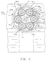
- the sealing assembly includes a front seal ring 138, a spindle carrier seal 140, an O-ring 142 and five retainer screws 144 (only one of which can be seen in Figures 6 and 13, but all five of which can be seen in Figure 5).
- the front seal ring 138 is coupled to the headstock upright 22a and includes a notch 148 in an inner peripheral surface which accommodates the spindle carrier seal 140.
- the seal 140 engages the outer peripheral surface 44 of the spindle carrier 30.
- the seal 140 includes a v-shaped cut out in its spindle carrier engaging surface to reduce the contact area and friction between the spindle carrier 30 and the seal.
- the front seal ring 138 is secured to the headstock upright end 120 by the five retainer screws 144 which thread into spaced apart apertures in the headstock upright end.
- the retainer screws 144 include cap portions which partially overlie and bear against the front seal ring forcing it against the shoulder 118a of the counterbore 118.
- the front seal ring 138 further includes a groove 149 on its outer peripheral surface.
- the O-ring 142 seats in the outer peripheral surface groove of the front seal ring 138 to provide a positive seal with the headstock upright 22a.
- each roller 126 forms an acute angle between the outer peripheral surface 44 of the spindle carrier 30 and an axis of rotation or central axis of the roller.
- the spindle carrier bearing assembly 112 is identical to bearing assembly 110 only the cone retaining structure and the sealing structure are somewhat different.
- the tapered rollers 128 of the spindle carrier bearing assembly are rotatably confined between an inner ring or cone 150 and an outer ring or cup 152.
- the cone 150 frictionally engages the outer peripheral surface 44 of the spindle carrier 30 and rotates with it when the carrier indexes.
- the cup 152 frictionally engages the headstock upright counterbore 122 and is wedged against a radially stepped portion or shoulder of counterbore 122a.
- the cup 152 is installed when the front spindle bearing cup 132 is installed, that is, before the spindle carrier 30 is inserted into the upright throughbores 24a, 24b.
- the cup 152 which has an outer diameter at room temperature just greater than the counterbore inner diameter at the same temperature
- the cup is subjected to cold temperatures to reduce its outer diameter and then force fit into the counterbore 122 and is seated against the counterbore shoulder 122a.
- the cone 150 which has an inner diameter at room temperature just less than the spindle carrier diameter at the same temperature, is heated to expand its inner diameter. The expanded cone 150 is then slid over the spindle carrier into contact with rollers 128.
- a rear retaining ring 156 is coupled to the spindle carrier 30 and overlies an outwardly facing portion of the cone.
- the ring 156 is secured to the spindle carrier 30 with fourteen hex head cap screws 158 (one of which can be seen in Figure 6 and all of which can be seen in Figure 4) extending through apertures in the ring and thread into aligned apertures in the headstock upright end 124. Tightening the screws 158 exerts an extremely large axial force on cone 130, approximately 15,000 psi.
- the axial force on cone 130 preloads both bearing assemblies 110, 112. Recall that the cone 130 of bearing assembly 110 is constrained to bear against the rollers 126 by the retaining assembly 133. Thus, when the rear retaining ring 156 exerts axial force on cone 150 and equal and opposite force is exerted by retaining assembly 133 on cone 130. The resultant of these large axial forces is a preloading or compressing of both sets of rollers 126, 128 to the extent that a diameter of each roller is reduced. A face of the rear retaining ring 156 is ground to the extent necessary to provide an appropriate fit subject to the axial tolerances of spindle carrier bearings 110, 112 and the spindle carrier 30. The preloading produces a highly stable spindle carrier position regardless of machining load or operating temperature.
- a sealing assembly 160 is coupled to the headstock upright 24b to prevent contaminants from entering the spindle carrier bearing assembly 112.
- the sealing assembly 160 includes a rear seal ring 162, a rear retaining ring seal 164, nine socket head cap screws 166 (only one of which can be seen in Figures 6 and four of which can be seen in Figure 4).
- the rear seal ring 162 is coupled to the headstock upright 22b and includes a notch 168 in an inner peripheral surface which accommodates the rear retaining ring seal 164.
- the seal 164 engages the outer peripheral surface of the rear retaining ring 156.
- the seal 164 includes a v-shaped cut out in its retaining ring engaging surface to reduce the contact area and friction between the retaining ring and the seal.
- the rear seal ring 162 is secured to the headstock upright end 124 by the nine socket head screws 166 which pass through spaced apart apertures in the seal ring and thread into aligned apertures in the headstock upright end.
- Figures 3, 6 and 13 show one 40a of the six spindles which is supported by two bearings, a front spindle bearing 200 disposed in bore 42a in a front portion 30a of the spindle carrier 30 and a rear spindle bearing 202 disposed in bore 43a in a rear portion 30b of the spindle carrier for allowing relative rotation between the spindle 40a and the spindle carrier 30.
- Each of the six spindles 40a-40f is similarly supported by identical pairs of spindle bearings (which for convenience will be referred to by the same reference numbers 200, 202) rotatably supported in the spindle carrier bores 42a-42f and 43a-43f.
- each of the rear spindle bearings 202 is advantageously preloaded by fluid pressure to insure precise positioning of the spindles (and thereby the workpieces supported by the spindles) with respect to the spindle carrier 30. Additionally, two fluid pressure seals are provided at each of the front spindle bearings 200 to block contaminants from infiltrating the bearings.
- a fluid transmission delivery system is provided to route pressurized fluid from an external source to the front and rear spindle bearings 200, 202.
- the spindle drive shaft 50 includes a longitudinal passageway 51 extending the length of the shaft
- a rotating union 204 ( Figure 3) threads (preferably a left handed thread) into a tapped hole in an end of the spindle drive shaft 50 disposed in the gearbox housing 14.
- the union 204 includes a side wall with a tapped hole 206 adapted to receive a coupling (not shown).
- An external source of pressurized fluid (not shown) is coupled to the tapped hole 208 to pressurize the spindle drive shaft passageway 51.
- the pressurized fluid preferably is air.
- a rotating fluid coupling structure 210 is provided to route the pressurized fluid in the spindle drive shaft passageway 51 to an fluid inlet opening 212 in the spindle carrier rear end 116.
- the fluid coupling structure 210 must be rotatable because of the relative rotation between the spindle drive shaft 50 and the spindle carrier 30.
- the fluid coupling structure 210 includes a rotating in-shaft union 214 which extends into the end of the drive shaft and is in fluid communication with the drive shaft passageway 51.
- the union 214 is secured in the spindle drive shaft by a trantorque coupling 216, which is coupled to spindle drive shaft drive gear 54, and a retaining ring 218.
- the union includes a threaded bore in an outwardly extending portion of the union adapted to receive a straight coupling 220.
- Straight coupling 220 is, in turn, connected to two coupled right angle couplings 222.
- An end of a flexible hose 224 is connected to an end of one of the right angle couplings 222 and coupled at the other end to a coupling 226 threaded into the spindle carrier fluid inlet opening 212 (the opening, not shown in Figures 3 and 6 is seen in Figure 7 and in section in Figure 10).
- the fluid coupling structure 210 rotates to supply pressurized fluid to the inlet opening 212.
- Figures 7-12 depict a fluid delivery manifold system defined by the spindle carrier 30 for supplying pressurized air input to the carrier through coupling 226 to the front and rear spindle bearings 200, 202 supporting the spindles.
- Figure 7 is an end view of the spindle carrier 30 with the individual spindles 40a-40f removed for ease in depiction.
- Figure 10 is a section view through the bore 43a supporting spindle 40a in conjunction with bore 42a.
- the fluid input opening 212 in the rear end 116 of the spindle carrier 30 has a threaded internal bore which accommodates coupling 226. Extending from input opening 212 is an entry passageway 222 which communicates with a circumferential notch in bore 43a which defines an annular passageway 224a.
- Each of the multiple spindles is surrounded by a similar passageways 224b-224f.
- the passageways 224a-224f are interconnected by drilled conduits 230 between spindle bores 43a-43f. These drilled conduits 230 are seen in phantom in the end view of Figure 7 and entries 232 to these conduits are depicted in Figure 10. Pressurized fluid is routed through the conduits 230 to pressurize each of the circumferentially extending passageways 224a-224f.
- each grease fitting 240 in fluid communication respective grease passageways 242 extend to openings in bores 43a-43f to permit lubrication of the six rear spindle bearings 202.
- the grease fitting 240 includes a check valve (not shown) to prevent reflux of injected grease.
- Corresponding weep holes 244 extending from the bores 43a-43f to the spindle carrier outer peripheral surface 44 are provided to allow excess grease to seep out of the respective rear spindle bearings.
- the pressure in the passageways 224a-224f applies a preload to the rear spindle bearings 202 disposed in the bores 43a-43f.
- the preferred rear spindle bearing 202 is commercially available from the Timkin Company under the trade designation "Hydra-Rib Bearing.”
- the structure of the "Hydra-Rib" rear spindle bearing is illustrated in Figure 12 and includes the cup 250 and a cone 252 which trap a set of tapered roller bearings 254. Individual rollers 254 are maintained in a spaced apart relationship by a roller bearing cage 255 of conventional design.
- the cup 250 includes a groove in its inner peripheral surface which seats a snap ring 256 and also defines a through passageway 257 for introduction of a fluid under pressure for applying a preload to the tapered roller bearings 254.
- the rear spindle bearings 202 are positioned in their respective bores 43a-43f such that the spindle bearing passageway 257 is aligned with and in fluid communication with the spindle carrier bore passageways 224a-224f.
- the piston ring 262 When fluid pressure is applied through passageway 257, the piston ring 262 is forcefully pushed against an edge of each tapered roller bearing 255 thereby loading the bearing 202.
- a ring seal 264 is provided to maintain a pressure seal between the pressurized passageway 254 and an interior region of the bearing.
- the cup also includes a lubrication passageway 268 which permits the injection of lubricant into a region where the piston ring 262 contacts roller bearing edges. Further details concerning the construction and arrangement of such a bearing are available in Timkin product literature which is incorporated herein by reference.
- the pressurized fluid which enters the spindle carrier 30 through the fluid inlet opening 212 is also used as a sealing mechanism to prevent contaminants from entering a region of the front spindle bearings 200 as relative rotation between the spindles 40a-40f and spindle carrier occurs.
- an axially extending bore 270 is drilled into the spindle carrier 30 from the carrier rear end 116. An opening of the bore is then sealed with a plug 272 (which also can be seen in Figure 7).
- the axial bore 270 provides a fluid delivery path for fluid under pressure in passageway 234a to bores 42a-42f in upright 22a.
- An angled bore 274 connects pressurized passageway 234a with axial bore 270, while angled bores 276, 278 provide fluid communication between axial bore 270 and bore 42a.
- the angled bore 274 is also seen in Figure 10.
- the bores 42a-42f are interconnected by two sets of drilled conduits (not shown but are axially aligned with conduits 230 seen in phantom in Figure 7) between bores.
- Entries 280, 282 to respective sets of drilled are seen in Figures 8 and 11.
- the pressurized fluid supplied to bore 42a via passageways 276, 278 to is routed through the respective sets of conduits to provide two air seal regions surrounding each of the front spindles bearings 200.
- each of the front spindle bearings 200 is comprised of a set of caged tapered rollers 290 secured between an inner ring or cone 292 coupled to an outer peripheral surface 296 of the spindle 40a.
- the rollers 290 are located and oriented so as to be aligned with the line of action of the front spindle carrier bearings 110. That is, lines drawn perpendicularly to a cone contacting surface each roller 290 would intersect in the at a point X ( Figure 3) which is situated forward of the front end 30' of the spindle carrier 30 and rearwardly of the plane Y-Y extending through a front surface of each spindle collet 92.
- three shallow grooves 298 are milled into the outer peripheral surface 296 of the spindle 40a rearwardly of the spindle nose 94.
- the grooves 298 serve as a labyrinth seal.
- the pressurized fluid routed to the bores 42a-42f through passageways 276, 278 and corresponding sets of conduits form an air seal on either side of the bearings 200 to further protect the bearings.
- the annular air seal member 300 is seated in a counterbored section of the spindle carrier 30 adjacent the carrier front end 120 and includes a conduit 302 which is in fluid communication with passageway 278.
- the air seal member 300 is comprised of impermeable bronze and is secured to the spindle carrier 30 by two screws 304. Two O-rings (not shown) seated in circumferential grooves 306 sealing engage a surface of the spindle carrier 30.
- an outlet end of the air seal member conduit 302 (that is, an end opposite an end adjacent the spindle carrier) is a permeable bronze ring 308.
- the pressurized air leaks through the ring 308 along the spindle outer peripheral surface 296 thereby preventing any contaminants which traversed the labyrinth seal from progressing to the front spindle bearing 200.
- a second annular air seal member 310 and permeable bronze ring 312 provide an air seal on the other or rearward side of the bearing 200.
- the second air seal member 310 is disposed in the spindle carrier counterbore and axially secured between a circumferential stepped portion 314 of the spindle carrier 30 and a vertically oriented surface of the bearing cup 294.
- the second air seal member 310 includes an air passage conduit 316 in fluid communication with passageway 276 and an O-ring (not shown) is disposed in an annular groove in an outer peripheral surface of the member to sealingly engage a surface of the spindle carrier 30.
- the pressurized air passes through conduit 316 and leaks through ring 312 to provide a second air seal. The air leaks out along the spindle outer peripheral surface 296.
- the advantage of having two air seals axially surrounding each of the front spindle bearing 200 is that the two air seal air flows intersect at the bearing and create a "dead" zone of air, that is, no air flow. All the leaking air must escape in an axial directions away from the bearing 200 taking any contaminants away from the bearing.
- the bar machine shown in the drawings is a six spindle machine wherein the spindles are sized to hold 1 1/4'' bar stock. It should be appreciated, however, that present invention is equally applicable to four or eight spindle bar machines and to bar machines having spindles sized to run other bar stock sizes. Moreover, the present invention could also be used advantageously in chuckers, which are similar in many respects to bar machines, e.g. an indexable spindle carrier mounted in a bore, the spindle carrier supporting a plurality of rotating spindles. In a chucker, workpieces are not defined by a section of bar stock pushed through a spindle.
- the workpieces are normally individual cast or forged parts which are inserted into an open spindle collet.
- the collet closes and the workpiece is secured in the rotating spindle.
- the spindle carrier indexes moving the spindle through successive indexing positions where machining operations are performed.
Landscapes
- Engineering & Computer Science (AREA)
- Mechanical Engineering (AREA)
- Turning (AREA)
Applications Claiming Priority (2)
| Application Number | Priority Date | Filing Date | Title |
|---|---|---|---|
| US297257 | 1994-08-26 | ||
| US08/297,257 US6389939B1 (en) | 1994-08-26 | 1994-08-26 | Multiple-spindle bar machine |
Publications (2)
| Publication Number | Publication Date |
|---|---|
| EP0704276A2 true EP0704276A2 (de) | 1996-04-03 |
| EP0704276A3 EP0704276A3 (de) | 1997-08-13 |
Family
ID=23145534
Family Applications (1)
| Application Number | Title | Priority Date | Filing Date |
|---|---|---|---|
| EP95113375A Withdrawn EP0704276A3 (de) | 1994-08-26 | 1995-08-25 | Mehrspindel-Drehbank |
Country Status (2)
| Country | Link |
|---|---|
| US (1) | US6389939B1 (de) |
| EP (1) | EP0704276A3 (de) |
Cited By (2)
| Publication number | Priority date | Publication date | Assignee | Title |
|---|---|---|---|---|
| EP1960139A4 (de) * | 2005-12-14 | 2010-11-17 | Brinkman Products Inc | Schmiersystem für ein automatisches schraubgerät mit mehreren spindeln |
| EP2942151A1 (de) * | 2011-09-12 | 2015-11-11 | Index-Werke GmbH & Co. KG Hahn & Tessky | Mehrspindeldrehmaschine |
Families Citing this family (7)
| Publication number | Priority date | Publication date | Assignee | Title |
|---|---|---|---|---|
| US6379728B1 (en) * | 2000-05-26 | 2002-04-30 | Eldon Roth | Method for producing a target PH in a foodstuff |
| DE20303147U1 (de) * | 2003-02-26 | 2003-04-30 | Deckel Maho Pfronten GmbH, 87459 Pfronten | Werkstückaufnahme für stangenförmige Werkstücke |
| US7104170B1 (en) | 2005-10-10 | 2006-09-12 | Basgall Robert M | Air release stock stop |
| DE102010002804A1 (de) * | 2010-03-12 | 2011-09-15 | Index-Werke Gmbh & Co. Kg Hahn & Tessky | Mehrspindeldrehmaschine |
| US10280505B2 (en) * | 2014-11-17 | 2019-05-07 | Integrated 3D Metallizing, Llc | Integrated 3D metallizer |
| JP6892594B2 (ja) * | 2017-03-14 | 2021-06-23 | スター精密株式会社 | 工作機械 |
| IT202000001054A1 (it) * | 2020-01-21 | 2021-07-21 | Grazioli Cesare S R L | Macchina transfer |
Family Cites Families (23)
| Publication number | Priority date | Publication date | Assignee | Title |
|---|---|---|---|---|
| CH52895A (fr) | 1910-07-02 | 1912-01-02 | Edouard Joly | Four à compartiments multiples |
| GB195280A (en) | 1922-04-18 | 1923-03-29 | Frederic Phelp Jones | Improvements in and relating to the manufacture of bricks |
| US2036685A (en) | 1934-01-19 | 1936-04-07 | Nat Acme Co | Spindle bearing for automatic multiple spindle screw machines |
| US2401072A (en) * | 1943-05-21 | 1946-05-28 | Morey Machinery Co Inc | Turret lathe headstock |
| DE1098325B (de) * | 1956-02-21 | 1961-01-26 | Fritz Petzoldt | Mehrspindeldrehautomat |
| US3317258A (en) | 1964-10-06 | 1967-05-02 | Leblond Mach Tool Co R K | Compensation for spindle creep due to bearing temperature |
| US3521526A (en) | 1968-11-18 | 1970-07-21 | Giddings & Lewis | Method and apparatus for positional control compensation for temperature changes in machine tool spindles |
| DE1903882B2 (de) | 1969-01-27 | 1973-03-08 | Werkzeugmaschinen Fabrik Gildemeister & Co AG, 4800 Bielefeld | Mehrspindel-drehautomat mit drehschaltbarer spindeltrommel und hydrodynamisch arbeitenden drehspindellagern |
| DE2107735C3 (de) | 1971-02-18 | 1974-01-17 | Werkzeugmaschinen-Fabrik Gildemeister & Co, Ag, 4800 Bielefeld | Mehrspindel-Drehautomat |
| US3785023A (en) | 1972-03-23 | 1974-01-15 | Timken Co | Method for adjusting tapered roller bearings and for assembling devices employing such bearings as journals |
| DE2410540C3 (de) * | 1974-03-06 | 1980-12-04 | Index-Werke Kg Hahn & Tessky, 7300 Esslingen | Pinolenvorrichtung |
| CH581518A5 (de) * | 1975-03-14 | 1976-11-15 | Eunipp Ag | |
| BR7506815A (pt) * | 1975-03-21 | 1976-09-21 | Hure Sa | Aperfeicoamentos em maquinas operatrizes com eixo porta-ferramentas rotativo |
| US4519734A (en) * | 1982-06-22 | 1985-05-28 | Ex-Cello-O Corporation | High speed spindle with preloaded bearings |
| EP0290693B1 (de) | 1987-05-14 | 1993-08-11 | Hofer-Tech Corporation | Mehrspindel-Futter-Drehautomat |
| US4665781A (en) * | 1985-02-25 | 1987-05-19 | Hofer Industries Inc. | Multi-spindle chucking machine |
| DE8509777U1 (de) | 1985-04-01 | 1986-10-02 | Maho Werkzeugmaschinenbau Babel & Co, 8962 Pfronten | Werkzeugmaschine zur Fräs- und Drehbearbeitung |
| US4611934A (en) * | 1985-09-09 | 1986-09-16 | Cincinnati Milacron Inc. | Device for preloading bearings |
| IL78582A0 (en) | 1986-04-22 | 1986-08-31 | Amcor Ltd | Air feed tube assembly for a pneumatic chuck |
| DE3633050C1 (de) * | 1986-09-29 | 1987-10-22 | Goetze Ag | Drehmaschine |
| EP0298672A3 (de) | 1987-07-08 | 1989-12-06 | Wickman Bennett Machine Tool Company Limited | Mehrspindlige Drehmaschine |
| JPH0236006A (ja) | 1988-07-21 | 1990-02-06 | Daihatsu Motor Co Ltd | 多軸ヘッド |
| US5111562A (en) | 1990-11-27 | 1992-05-12 | Versa Tech Engineering | Spindle apparatus for holding a workpiece |
-
1994
- 1994-08-26 US US08/297,257 patent/US6389939B1/en not_active Expired - Lifetime
-
1995
- 1995-08-25 EP EP95113375A patent/EP0704276A3/de not_active Withdrawn
Non-Patent Citations (1)
| Title |
|---|
| NATIONAL ACME DIVISION: "Handbook for Operators - Acme Gridley Multiple Spindle Bar Machines", 1980, ACME-CLEVELAND CORPORATION |
Cited By (3)
| Publication number | Priority date | Publication date | Assignee | Title |
|---|---|---|---|---|
| EP1960139A4 (de) * | 2005-12-14 | 2010-11-17 | Brinkman Products Inc | Schmiersystem für ein automatisches schraubgerät mit mehreren spindeln |
| EP2942151A1 (de) * | 2011-09-12 | 2015-11-11 | Index-Werke GmbH & Co. KG Hahn & Tessky | Mehrspindeldrehmaschine |
| EP3381605A1 (de) * | 2011-09-12 | 2018-10-03 | Index-Werke GmbH & Co. KG Hahn & Tessky | Mehrspindeldrehmaschine |
Also Published As
| Publication number | Publication date |
|---|---|
| US6389939B1 (en) | 2002-05-21 |
| EP0704276A3 (de) | 1997-08-13 |
Similar Documents
| Publication | Publication Date | Title |
|---|---|---|
| US6729813B2 (en) | Spindlehead for tools | |
| US7509720B2 (en) | Continuous tool rotation tool turret | |
| US5544985A (en) | Deep bore drilling apparatus with rotatable single tube system | |
| CA2087798C (en) | High speed spindle unit and driver | |
| KR101676885B1 (ko) | 머시닝 센터용 유니버셜 툴 마운팅 시스템 | |
| US4571129A (en) | Mandrel assembly | |
| US3020057A (en) | Rotary fluid supply system | |
| US5918514A (en) | Multi-spindle CNC lathe | |
| US6389939B1 (en) | Multiple-spindle bar machine | |
| US7344341B2 (en) | Drill | |
| EP2529883A1 (de) | Hauptwellenvorrichtung für eine bohrmaschine | |
| US5351376A (en) | Machine tool | |
| MX2011006311A (es) | Ensamble de herramienta automatica. | |
| EP1177847A1 (de) | Gewindebohrerhalter | |
| KR19980071543A (ko) | 회전하는 기계부로 혼합 유체를 공급하기 위한 방법 및 장치 | |
| US5133629A (en) | Tool holding assembly provided with a feeler device | |
| CA2156334C (en) | Tool for precise machining of metal | |
| DE19642975C2 (de) | Werkzeugrevolver für eine Werkzeugmaschine | |
| KR20070029598A (ko) | 공작기계 또는 그들의 부품에서 베어링 위치의 윤활 방법및 장치 | |
| CN116532731B (zh) | 滚齿装置及数控滚齿机 | |
| US3469496A (en) | Quill support for machine tool spindles | |
| EP3593943B1 (de) | Hauptspindelvorrichtung für eine werkzeugmaschine | |
| CN214868972U (zh) | 动力头、动力装置以及机床 | |
| CN109604744B (zh) | 大长径比内螺纹拉丝系统及拉丝方法 | |
| JP3331869B2 (ja) | タレット装置における流体分配装置 |
Legal Events
| Date | Code | Title | Description |
|---|---|---|---|
| PUAI | Public reference made under article 153(3) epc to a published international application that has entered the european phase |
Free format text: ORIGINAL CODE: 0009012 |
|
| AK | Designated contracting states |
Kind code of ref document: A2 Designated state(s): DE FR GB IT |
|
| RAP1 | Party data changed (applicant data changed or rights of an application transferred) |
Owner name: DEVLIEG-BULLARD, INC. |
|
| PUAL | Search report despatched |
Free format text: ORIGINAL CODE: 0009013 |
|
| AK | Designated contracting states |
Kind code of ref document: A3 Designated state(s): DE FR GB IT |
|
| 17P | Request for examination filed |
Effective date: 19980204 |
|
| 17Q | First examination report despatched |
Effective date: 19980930 |
|
| STAA | Information on the status of an ep patent application or granted ep patent |
Free format text: STATUS: THE APPLICATION IS DEEMED TO BE WITHDRAWN |
|
| 18D | Application deemed to be withdrawn |
Effective date: 20000301 |