EP0704295A1 - Drahtverstärkung einer Gummimatrix - Google Patents
Drahtverstärkung einer Gummimatrix Download PDFInfo
- Publication number
- EP0704295A1 EP0704295A1 EP95114207A EP95114207A EP0704295A1 EP 0704295 A1 EP0704295 A1 EP 0704295A1 EP 95114207 A EP95114207 A EP 95114207A EP 95114207 A EP95114207 A EP 95114207A EP 0704295 A1 EP0704295 A1 EP 0704295A1
- Authority
- EP
- European Patent Office
- Prior art keywords
- wire
- sections
- rotor
- support
- cylindrical chamber
- Prior art date
- Legal status (The legal status is an assumption and is not a legal conclusion. Google has not performed a legal analysis and makes no representation as to the accuracy of the status listed.)
- Granted
Links
Images



Classifications
-
- B—PERFORMING OPERATIONS; TRANSPORTING
- B21—MECHANICAL METAL-WORKING WITHOUT ESSENTIALLY REMOVING MATERIAL; PUNCHING METAL
- B21F—WORKING OR PROCESSING OF METAL WIRE
- B21F11/00—Cutting wire
-
- B—PERFORMING OPERATIONS; TRANSPORTING
- B21—MECHANICAL METAL-WORKING WITHOUT ESSENTIALLY REMOVING MATERIAL; PUNCHING METAL
- B21F—WORKING OR PROCESSING OF METAL WIRE
- B21F1/00—Bending wire other than coiling; Straightening wire
- B21F1/02—Straightening
- B21F1/026—Straightening and cutting
-
- B—PERFORMING OPERATIONS; TRANSPORTING
- B29—WORKING OF PLASTICS; WORKING OF SUBSTANCES IN A PLASTIC STATE IN GENERAL
- B29C—SHAPING OR JOINING OF PLASTICS; SHAPING OF MATERIAL IN A PLASTIC STATE, NOT OTHERWISE PROVIDED FOR; AFTER-TREATMENT OF THE SHAPED PRODUCTS, e.g. REPAIRING
- B29C70/00—Shaping composites, i.e. plastics material comprising reinforcements, fillers or preformed parts, e.g. inserts
- B29C70/68—Shaping composites, i.e. plastics material comprising reinforcements, fillers or preformed parts, e.g. inserts by incorporating or moulding on preformed parts, e.g. inserts or layers, e.g. foam blocks
- B29C70/82—Forcing wires, nets or the like partially or completely into the surface of an article, e.g. by cutting and pressing
-
- B—PERFORMING OPERATIONS; TRANSPORTING
- B29—WORKING OF PLASTICS; WORKING OF SUBSTANCES IN A PLASTIC STATE IN GENERAL
- B29D—PRODUCING PARTICULAR ARTICLES FROM PLASTICS OR FROM SUBSTANCES IN A PLASTIC STATE
- B29D30/00—Producing pneumatic or solid tyres or parts thereof
- B29D30/06—Pneumatic tyres or parts thereof (e.g. produced by casting, moulding, compression moulding, injection moulding, centrifugal casting)
- B29D30/38—Textile inserts, e.g. cord or canvas layers, for tyres; Treatment of inserts prior to building the tyre
-
- B—PERFORMING OPERATIONS; TRANSPORTING
- B29—WORKING OF PLASTICS; WORKING OF SUBSTANCES IN A PLASTIC STATE IN GENERAL
- B29K—INDEXING SCHEME ASSOCIATED WITH SUBCLASSES B29B, B29C OR B29D, RELATING TO MOULDING MATERIALS OR TO MATERIALS FOR MOULDS, REINFORCEMENTS, FILLERS OR PREFORMED PARTS, e.g. INSERTS
- B29K2021/00—Use of unspecified rubbers as moulding material
-
- B—PERFORMING OPERATIONS; TRANSPORTING
- B29—WORKING OF PLASTICS; WORKING OF SUBSTANCES IN A PLASTIC STATE IN GENERAL
- B29K—INDEXING SCHEME ASSOCIATED WITH SUBCLASSES B29B, B29C OR B29D, RELATING TO MOULDING MATERIALS OR TO MATERIALS FOR MOULDS, REINFORCEMENTS, FILLERS OR PREFORMED PARTS, e.g. INSERTS
- B29K2105/00—Condition, form or state of moulded material or of the material to be shaped
- B29K2105/06—Condition, form or state of moulded material or of the material to be shaped containing reinforcements, fillers or inserts
- B29K2105/08—Condition, form or state of moulded material or of the material to be shaped containing reinforcements, fillers or inserts of continuous length, e.g. cords, rovings, mats, fabrics, strands or yarns
- B29K2105/10—Cords, strands or rovings, e.g. oriented cords, strands or rovings
- B29K2105/101—Oriented
-
- Y—GENERAL TAGGING OF NEW TECHNOLOGICAL DEVELOPMENTS; GENERAL TAGGING OF CROSS-SECTIONAL TECHNOLOGIES SPANNING OVER SEVERAL SECTIONS OF THE IPC; TECHNICAL SUBJECTS COVERED BY FORMER USPC CROSS-REFERENCE ART COLLECTIONS [XRACs] AND DIGESTS
- Y10—TECHNICAL SUBJECTS COVERED BY FORMER USPC
- Y10S—TECHNICAL SUBJECTS COVERED BY FORMER USPC CROSS-REFERENCE ART COLLECTIONS [XRACs] AND DIGESTS
- Y10S156/00—Adhesive bonding and miscellaneous chemical manufacture
- Y10S156/906—Off-drum manufacture of tire fabric or ply
-
- Y—GENERAL TAGGING OF NEW TECHNOLOGICAL DEVELOPMENTS; GENERAL TAGGING OF CROSS-SECTIONAL TECHNOLOGIES SPANNING OVER SEVERAL SECTIONS OF THE IPC; TECHNICAL SUBJECTS COVERED BY FORMER USPC CROSS-REFERENCE ART COLLECTIONS [XRACs] AND DIGESTS
- Y10—TECHNICAL SUBJECTS COVERED BY FORMER USPC
- Y10T—TECHNICAL SUBJECTS COVERED BY FORMER US CLASSIFICATION
- Y10T156/00—Adhesive bonding and miscellaneous chemical manufacture
- Y10T156/12—Surface bonding means and/or assembly means with cutting, punching, piercing, severing or tearing
- Y10T156/1317—Means feeding plural workpieces to be joined
- Y10T156/1322—Severing before bonding or assembling of parts
- Y10T156/133—Delivering cut part to indefinite or running length web
- Y10T156/1335—Cutter also delivers cut piece
Definitions
- the present invention relates to the reinforcement of a matrix of rubbery material by wires.
- the present invention relates to the manufacture of tires, more particularly the manufacture of reinforcements, regardless of the location in a tire where it is envisaged to make or use such a reinforcement.
- thread must of course be understood in a completely general sense, including a monofilament, a multifilament, a cable or a twist or an equivalent assembly, and this whatever the material constituting the thread or the treatment that it has undergone, for example, a surface treatment to promote its spontaneous adhesion to a support on which it is deposited, or its intimate bond with rubber.
- the objective of the present invention is to propose a means of depositing sections of son on a matrix of material rubbery, which is very economical to manufacture and implement.
- the objective of the present invention is to propose a manufacturing process which makes it possible to produce, from a spool of wire, both in the form of a semi-finished product and directly on a raw blank during manufacture, several categories of non-circumferential wire reinforcements.
- One of the objectives of the invention with regard to the manufacture of semi-finished products is to propose the means making it possible to produce reinforcing plies such as crown plies or carcass plies as deposited quite commonly on drums by means of guideways called "servicers”.
- Another objective of the invention with regard to the manufacture of semi-finished products is to propose the means making it possible to produce strips of a matrix of reinforced rubber material, necessary for the manufacture of belts such as those appearing in FIGS. 6 and 7, or 10 and 11 of US Pat. No. 1,894,237, containing non-circumferential cords, or else those necessary for the manufacture of the tire described in patent application EP 95 / 107861.7.
- a "semi-finished product" having the appearance of a ribbon, of relatively small width, comprising a matrix of rubbery material in which are embedded, or at least on which are fixed by gluing, is called “strip". reinforcing wires extending transversely in said strip.
- the width is considered to be small when it is necessary, in a radial section of the tire, to use more than one strip to carry out the entire reinforcement considered, for example at least two strips over the height of the sidewall in a carcass, or at least two strips across the width of the belt.
- the support is a strip of raw rubber, continuously extruded, on which said sections are stored parallel to each other. to others.
- the support is a raw tire during manufacture, on which said sections are stored in the place provided by the architecture of the tire, forming a constant angle.
- the essential organs of a machine according to the invention constitute a device 1 ensuring the removal of sections of wire and transporting said sections on said support.
- a device 1 ensuring the removal of sections of wire and transporting said sections on said support.
- the support 2 is here a strip of raw rubber, extruded through a die 20, and is supported downstream of the extrusion, by a roller 21.
- the device 1 comprises a casing 10 in which is hollowed out a cylindrical chamber, delimited by a cylindrical wall 11, and by two lateral flat walls 12 perpendicular to the axis aa of said cylindrical chamber.
- One of the main organs of the device is a rotor A, which can rotate about the axis aa of said cylindrical chamber.
- This rotor A is provided with pallets 13 oriented transversely, said pallets delimiting with at least part of the cylindrical wall 11 of the cylindrical chamber each a housing for receiving the wire.
- a hole 14 for introducing the wire is located in one of the two side walls 12 of said cylindrical chamber, facing said housings.
- An exhaust opening 15 is arranged transversely in said cylindrical wall 11.
- the outside diameter of the rotor is of course less than the inside diameter of the cylindrical chamber at least by a value corresponding to the thickness of the wire used. In general, this diameter of the rotor is less than the inside diameter of the cylindrical chamber by a value slightly greater than the diameter of the orifice 14, itself of slightly larger diameter than the largest of the wire diameters that it is desired to be able to use.
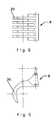
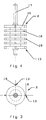
- the rotor A comprises a set of discs 16 (see FIG. 4), integral with a shaft 17, and therefore kept regularly spaced and without relative rotation between them. It is thus possible to interpose the teeth 30 of the comb B (see FIGS. 5 and 6) between the discs 16.
- Each disc 16 is provided with an always identical number of lugs 18 regularly distributed around its periphery.
- the pins 18 belonging to different discs 16 are here arranged opposite each other. In the particular case illustrated here, the lugs 18 are aligned, parallel to the axis aa of the rotor A.
- Each group of adjacent lugs 18 transversely forms said pallets 13. More generally, the lugs belonging to different discs 16 form said pallets 13.
- the comb is shaped and arranged so as to guide each section 40 of wire towards the exhaust opening 15. It makes it possible to maintain a passage section which is just sufficient for a section 40 of wire: the sections 40 which have reached this place can push one on the other, they thus travel in a certain direction towards the exhaust opening.
- each section 40 placed on the rubber band constituting the support 2 is preferably rectilinear, preferably, in order to make the shape taken by each section 40 very reliable and perfectly reproducible, the teeth 30 of the comb B form, with an opposite wall 31, an exhaust passage 32 in which the clearance existing between said teeth 30 and said opposite wall 31 decreases when one moves towards the exhaust opening 15.
- the machine can advantageously comprise a rotary roller C whose role is to assist in the deposition of the sections on the rubber band, by a rolling effect.
- the roller C is here arranged with an axis of rotation parallel to the axis of rotation aa of the rotor A. Between the roller C and the rubber band, a slight clearance remains, less than the thickness of the sections of wire 40 to be embedded in the rubber matrix.
- the roller C has its cylindrical surface 50 at said sections 40 near said exhaust opening 15, and accompanies the sections 40 until they adhere to the ribbon of raw rubber material.
- the rotary roller C can be designed so as to guarantee a very regular spacing between all the sections 40 of wire which it is desired to lay parallel to each other.
- the roller C has, on its cylindrical surface 50, a plurality of rectilinear grooves 51 parallel to the axis of rotation of the roller C, each capable of receiving a section 40 of wire.
- the machine described must be associated with a feeder (not shown) capable of introducing the wire used by the orifice 14.
- a feeder (not shown) capable of introducing the wire used by the orifice 14.
- the wire is pinched between two rollers covered with a non-slip coating. At least one of the rollers is motorized. It is therefore possible to continuously control the length of wire introduced through the orifice 14 by knowing the tangential speed of the rollers. Any type of wire can be called and measured this way.
- patent application EP 0519295 in which numerous information relating to the motorization of a wire is given.
- each section 40 introduced into a housing has a length which is not greater than the length of the rotor A measured along a pallet 13, from one side wall 12 to the other.
- the cut sections have a length such that they occupy, apart from a functional clearance, substantially the entire length available between the side walls 12.
- the motorization of the device can very simply be carried out at constant speed. Likewise, so that the pitch of laying of the sections of wire 40 is regular, the synchronous control mentioned above is also synchronized with the movement of the support, that is to say here with the movement of the rubber band 2 under the device 1 .
- the operation of the device is as follows.
- the rotation of the rotor A cuts the wire to take sections 40 thereof, thanks to the cooperation between the edge 180 of each pallet 13 and the adjacent side wall 12, more precisely between the edge 180 of the lugs 18 of the disc 16 adjacent to the side wall 12, and the material constituting the latter around the insertion orifice 14.
- the constituent materials are chosen and / or treated so as to withstand the stresses due to this cutting by shearing of the wire.
- this possibility can be combined with the previous one: the device 1 in itself is designed or adjusted to operate, at the optimum, at a given characteristic angle, and a small range of angles can be traversed by inclination of the device 1 relative to the direction of travel of the support 2.
- the strip thus formed comprises a matrix of rubbery material reinforced essentially by wires 40 placed side by side, and extending transversely, that is to say over most of the width of the rubber band 2.
- the sections 40 encrusted on said ribbon 2 develop from one edge to the other of the strip.
- the wires 40 are arranged at the desired angle as a function of the use of the strip in the tire that it is desired to manufacture.
- the scrolling of the ribbon 2 would form the desired angle relative to the plane of the figure, namely would form the angle at which one wishes that the wires are arranged in top ply.
- the range of angles that can be scanned using the invention as described above is from 90 ° to about 45 °.
- roller C whose axis of rotation remains perpendicular to the direction of travel of the support, the grooves 51 being hollowed out at an adequate angle to the direction of the axis of the roller C, as explained above.
Landscapes
- Engineering & Computer Science (AREA)
- Mechanical Engineering (AREA)
- Chemical & Material Sciences (AREA)
- Composite Materials (AREA)
- Textile Engineering (AREA)
- Tyre Moulding (AREA)
- Moulding By Coating Moulds (AREA)
Applications Claiming Priority (2)
| Application Number | Priority Date | Filing Date | Title |
|---|---|---|---|
| FR9411776A FR2725153A1 (fr) | 1994-09-29 | 1994-09-29 | Renforcement d'une matrice en materiau caoutchouteux par des fils |
| FR9411776 | 1994-09-29 |
Publications (2)
| Publication Number | Publication Date |
|---|---|
| EP0704295A1 true EP0704295A1 (de) | 1996-04-03 |
| EP0704295B1 EP0704295B1 (de) | 1998-02-11 |
Family
ID=9467500
Family Applications (1)
| Application Number | Title | Priority Date | Filing Date |
|---|---|---|---|
| EP95114207A Expired - Lifetime EP0704295B1 (de) | 1994-09-29 | 1995-09-11 | Drahtverstärkung einer Gummimatrix |
Country Status (5)
| Country | Link |
|---|---|
| US (1) | US5609705A (de) |
| EP (1) | EP0704295B1 (de) |
| JP (1) | JP3705374B2 (de) |
| DE (1) | DE69501608T2 (de) |
| FR (1) | FR2725153A1 (de) |
Families Citing this family (2)
| Publication number | Priority date | Publication date | Assignee | Title |
|---|---|---|---|---|
| FR3099890A1 (fr) * | 2019-08-12 | 2021-02-19 | Compagnie Generale Des Etablissements Michelin | Machine de Guidage et de Maintien des Fils et Méthode d’Utilisation |
| US12558822B2 (en) | 2019-08-12 | 2026-02-24 | Compagnie Generale Des Etablissements Michelin | Filament guiding and retention machine and method of use |
Citations (6)
| Publication number | Priority date | Publication date | Assignee | Title |
|---|---|---|---|---|
| GB191739A (en) * | 1923-01-10 | 1924-02-28 | Hermann Debor | Improvements in pneumatic tyres |
| US1894237A (en) | 1930-05-31 | 1933-01-10 | Goodyear Tire & Rubber | Breaker strip |
| US2441071A (en) * | 1943-04-26 | 1948-05-04 | Gen Tire & Rubber Co | Pneumatic tire and method of making same |
| US3894906A (en) | 1973-06-01 | 1975-07-15 | Nat Standard Co | Apparatus for making tire breakers |
| DE3215604A1 (de) * | 1982-04-27 | 1983-11-03 | Leschus, geb. Putsch, Hildegard, 5600 Wuppertal | Fugenband sowie verfahren und vorrichtung zu seiner herstellung |
| EP0489352A1 (de) * | 1990-12-04 | 1992-06-10 | Bridgestone Corporation | Verfahren zur Herstellung einer verstärkten Lage für die Karkasse eines Reifens |
Family Cites Families (4)
| Publication number | Priority date | Publication date | Assignee | Title |
|---|---|---|---|---|
| GB1157112A (en) * | 1966-04-26 | 1969-07-02 | John Bagnall | Improvements in Carrier Bags |
| FR2599297B1 (fr) * | 1986-06-02 | 1988-08-12 | Michelin & Cie | Procede et machine de fabrication d'un renforcement pour pneumatiques |
| FR2669574B1 (fr) * | 1990-11-26 | 1994-11-18 | Aerospatiale | Procede et machine pour la fabrication d'une feuille complexe etanche, de forme quelconque, comportant une armature interne, et feuille ainsi obtenue. |
| FR2677578A1 (fr) * | 1991-06-17 | 1992-12-18 | Sedepro | Procede de fabrication d'un pneumatique et machines pour la mise en óoeuvre de ce procede. |
-
1994
- 1994-09-29 FR FR9411776A patent/FR2725153A1/fr active Pending
-
1995
- 1995-09-11 DE DE69501608T patent/DE69501608T2/de not_active Expired - Fee Related
- 1995-09-11 EP EP95114207A patent/EP0704295B1/de not_active Expired - Lifetime
- 1995-09-28 US US08/535,884 patent/US5609705A/en not_active Expired - Lifetime
- 1995-09-29 JP JP27711595A patent/JP3705374B2/ja not_active Expired - Fee Related
Patent Citations (6)
| Publication number | Priority date | Publication date | Assignee | Title |
|---|---|---|---|---|
| GB191739A (en) * | 1923-01-10 | 1924-02-28 | Hermann Debor | Improvements in pneumatic tyres |
| US1894237A (en) | 1930-05-31 | 1933-01-10 | Goodyear Tire & Rubber | Breaker strip |
| US2441071A (en) * | 1943-04-26 | 1948-05-04 | Gen Tire & Rubber Co | Pneumatic tire and method of making same |
| US3894906A (en) | 1973-06-01 | 1975-07-15 | Nat Standard Co | Apparatus for making tire breakers |
| DE3215604A1 (de) * | 1982-04-27 | 1983-11-03 | Leschus, geb. Putsch, Hildegard, 5600 Wuppertal | Fugenband sowie verfahren und vorrichtung zu seiner herstellung |
| EP0489352A1 (de) * | 1990-12-04 | 1992-06-10 | Bridgestone Corporation | Verfahren zur Herstellung einer verstärkten Lage für die Karkasse eines Reifens |
Also Published As
| Publication number | Publication date |
|---|---|
| JP3705374B2 (ja) | 2005-10-12 |
| US5609705A (en) | 1997-03-11 |
| DE69501608T2 (de) | 1998-06-04 |
| JPH08244120A (ja) | 1996-09-24 |
| DE69501608D1 (de) | 1998-03-19 |
| FR2725153A1 (fr) | 1996-04-05 |
| EP0704295B1 (de) | 1998-02-11 |
Similar Documents
| Publication | Publication Date | Title |
|---|---|---|
| EP0248301B1 (de) | Verfahren und Vorrichtung zur Herstellung von Verstärkungen für Reifen | |
| EP1517781B1 (de) | Vorrichtung zur herstellung einer verstärkungsstruktur für einen reifen mit einem wulstfahnendrehmechanismus | |
| CA1311671C (fr) | Procede et appareil de fabrication de renforcements pour pneumatiques | |
| CA2071445C (fr) | Procede de fabrication d'un pneumatique et machines pour la mise en oeuvre de ce procede | |
| EP0656853B1 (de) | Verfahren zum verpacken von ladungen mittels einer streckfolie, maschine und folie zur ausübung des verfahrens | |
| FR2744598A1 (fr) | Procede et appareil de production d'un aliment cylindrique, et aliment cylindrique | |
| EP1513672B1 (de) | Herstellung einer reifenverstärkungsstruktur mit der volumenregelung der matrix | |
| EP1147864A2 (de) | Schneidevorrichtung mit hoher Geschwindigkeit zum schneiden von Reifenverstärkungselementen | |
| EP0704295B1 (de) | Drahtverstärkung einer Gummimatrix | |
| CH635135A5 (fr) | Procede et dispositif pour la coupe d'un cable de filaments continus et l'ouverture en continu des fibres obtenues. | |
| EP1426170B1 (de) | Vorrichtung mit mehreren Auftragungsarmen zur Herstellung eines Verstärkungselements für Luftreifen | |
| EP1838520A1 (de) | Verfahren und vorrichtung zur herstellung und anordnung einer umfangsverstärkung für einen reifen und gemäss dem verfahren erhaltener reifen | |
| EP0647518B1 (de) | Vorrichtung und Verfahren zur seriellen Herstellung von faserverstärkten Harzteilen | |
| EP1426169B1 (de) | Vorrichtung zur Herstellung eines Verstärkungselements für grossformatige Luftreifen | |
| EP1590169B1 (de) | Eine mit einer drahtführungseinrichtung ausgerüstete vorrichtung zur herstellung von verstärkungselementen für luftreifen und ein herstellungsverfahren unter verwendung einer solchen vorrichtung. | |
| EP1711335A1 (de) | Vorrichtung zur herstellung einer reifenverstärkung | |
| FR2543058A1 (fr) | Procede et dispositif de fabrication par extrusion de composants en matiere elastomere | |
| EP1279484B1 (de) | Verfahren und Vorrichtung zur Herstellung einer Reifenverstärkungsstruktur | |
| CH426241A (fr) | Procédé de fabrication de pneumatiques, pneumatique fabriqué selon ce procédé et appareil pour la mise en oeuvre de ce procédé | |
| EP4330006B1 (de) | Verbessertes verfahren und vorrichtung zum kontinuierlichen aufwickeln von gummistreifen zu spulen | |
| EP1824666B1 (de) | Vorrichtung zur herstellung einer verstärkung für einen luftreifen | |
| WO1989010834A1 (fr) | Procede et appareil pour enduire de caoutchouc des fils deroules en parallele et produire ainsi une nappe |
Legal Events
| Date | Code | Title | Description |
|---|---|---|---|
| PUAI | Public reference made under article 153(3) epc to a published international application that has entered the european phase |
Free format text: ORIGINAL CODE: 0009012 |
|
| AK | Designated contracting states |
Kind code of ref document: A1 Designated state(s): DE ES FR GB IT LU |
|
| 17P | Request for examination filed |
Effective date: 19961004 |
|
| GRAG | Despatch of communication of intention to grant |
Free format text: ORIGINAL CODE: EPIDOS AGRA |
|
| 17Q | First examination report despatched |
Effective date: 19970409 |
|
| GRAG | Despatch of communication of intention to grant |
Free format text: ORIGINAL CODE: EPIDOS AGRA |
|
| GRAH | Despatch of communication of intention to grant a patent |
Free format text: ORIGINAL CODE: EPIDOS IGRA |
|
| GRAH | Despatch of communication of intention to grant a patent |
Free format text: ORIGINAL CODE: EPIDOS IGRA |
|
| GRAA | (expected) grant |
Free format text: ORIGINAL CODE: 0009210 |
|
| AK | Designated contracting states |
Kind code of ref document: B1 Designated state(s): DE ES FR GB IT LU |
|
| PG25 | Lapsed in a contracting state [announced via postgrant information from national office to epo] |
Ref country code: IT Free format text: LAPSE BECAUSE OF FAILURE TO SUBMIT A TRANSLATION OF THE DESCRIPTION OR TO PAY THE FEE WITHIN THE PRE;WARNING: LAPSES OF ITALIAN PATENTS WITH EFFECTIVE DATE BEFORE 2007 MAY HAVE OCCURRED AT ANY TIME BEFORE 2007. THE CORRECT EFFECTIVE DATE MAY BE DIFFERENT FROM THE ONE RECORDED.SCRIBED TIME-LIMIT Effective date: 19980211 Ref country code: ES Free format text: THE PATENT HAS BEEN ANNULLED BY A DECISION OF A NATIONAL AUTHORITY Effective date: 19980211 |
|
| REF | Corresponds to: |
Ref document number: 69501608 Country of ref document: DE Date of ref document: 19980319 |
|
| GBT | Gb: translation of ep patent filed (gb section 77(6)(a)/1977) |
Effective date: 19980401 |
|
| PLBE | No opposition filed within time limit |
Free format text: ORIGINAL CODE: 0009261 |
|
| STAA | Information on the status of an ep patent application or granted ep patent |
Free format text: STATUS: NO OPPOSITION FILED WITHIN TIME LIMIT |
|
| 26N | No opposition filed | ||
| REG | Reference to a national code |
Ref country code: GB Ref legal event code: IF02 |
|
| PGFP | Annual fee paid to national office [announced via postgrant information from national office to epo] |
Ref country code: GB Payment date: 20050830 Year of fee payment: 11 |
|
| PGFP | Annual fee paid to national office [announced via postgrant information from national office to epo] |
Ref country code: LU Payment date: 20051005 Year of fee payment: 11 |
|
| REG | Reference to a national code |
Ref country code: FR Ref legal event code: TP |
|
| GBPC | Gb: european patent ceased through non-payment of renewal fee |
Effective date: 20060911 |
|
| PG25 | Lapsed in a contracting state [announced via postgrant information from national office to epo] |
Ref country code: GB Free format text: LAPSE BECAUSE OF NON-PAYMENT OF DUE FEES Effective date: 20060911 |
|
| PG25 | Lapsed in a contracting state [announced via postgrant information from national office to epo] |
Ref country code: LU Free format text: LAPSE BECAUSE OF NON-PAYMENT OF DUE FEES Effective date: 20060911 |
|
| PGFP | Annual fee paid to national office [announced via postgrant information from national office to epo] |
Ref country code: FR Payment date: 20080912 Year of fee payment: 14 |
|
| PGFP | Annual fee paid to national office [announced via postgrant information from national office to epo] |
Ref country code: DE Payment date: 20080919 Year of fee payment: 14 |
|
| REG | Reference to a national code |
Ref country code: FR Ref legal event code: ST Effective date: 20100531 |
|
| PG25 | Lapsed in a contracting state [announced via postgrant information from national office to epo] |
Ref country code: FR Free format text: LAPSE BECAUSE OF NON-PAYMENT OF DUE FEES Effective date: 20090930 Ref country code: DE Free format text: LAPSE BECAUSE OF NON-PAYMENT OF DUE FEES Effective date: 20100401 |