EP0704373A2 - Entfaltungsgelenkvorrichtung - Google Patents
Entfaltungsgelenkvorrichtung Download PDFInfo
- Publication number
- EP0704373A2 EP0704373A2 EP95306759A EP95306759A EP0704373A2 EP 0704373 A2 EP0704373 A2 EP 0704373A2 EP 95306759 A EP95306759 A EP 95306759A EP 95306759 A EP95306759 A EP 95306759A EP 0704373 A2 EP0704373 A2 EP 0704373A2
- Authority
- EP
- European Patent Office
- Prior art keywords
- hinge arm
- hinge
- deployment
- deployed position
- stationary bracket
- Prior art date
- Legal status (The legal status is an assumption and is not a legal conclusion. Google has not performed a legal analysis and makes no representation as to the accuracy of the status listed.)
- Granted
Links
Images




Classifications
-
- E—FIXED CONSTRUCTIONS
- E05—LOCKS; KEYS; WINDOW OR DOOR FITTINGS; SAFES
- E05F—DEVICES FOR MOVING WINGS INTO OPEN OR CLOSED POSITION; CHECKS FOR WINGS; WING FITTINGS NOT OTHERWISE PROVIDED FOR, CONCERNED WITH THE FUNCTIONING OF THE WING
- E05F1/00—Closers or openers for wings, not otherwise provided for in this subclass
- E05F1/08—Closers or openers for wings, not otherwise provided for in this subclass spring-actuated, e.g. for horizontally sliding wings
- E05F1/10—Closers or openers for wings, not otherwise provided for in this subclass spring-actuated, e.g. for horizontally sliding wings for swinging wings, e.g. counterbalance
- E05F1/12—Mechanisms in the shape of hinges or pivots, operated by springs
- E05F1/1207—Mechanisms in the shape of hinges or pivots, operated by springs with a coil spring parallel with the pivot axis
-
- B—PERFORMING OPERATIONS; TRANSPORTING
- B64—AIRCRAFT; AVIATION; COSMONAUTICS
- B64G—COSMONAUTICS; VEHICLES OR EQUIPMENT THEREFOR
- B64G1/00—Cosmonautic vehicles
- B64G1/22—Parts of, or equipment specially adapted for fitting in or to, cosmonautic vehicles
-
- E—FIXED CONSTRUCTIONS
- E05—LOCKS; KEYS; WINDOW OR DOOR FITTINGS; SAFES
- E05D—HINGES OR SUSPENSION DEVICES FOR DOORS, WINDOWS OR WINGS
- E05D11/00—Additional features or accessories of hinges
- E05D11/10—Devices for preventing movement between relatively-movable hinge parts
- E05D11/1007—Devices for preventing movement between relatively-movable hinge parts with positive locking
-
- H—ELECTRICITY
- H01—ELECTRIC ELEMENTS
- H01Q—ANTENNAS, i.e. RADIO AERIALS
- H01Q1/00—Details of, or arrangements associated with, antennas
- H01Q1/27—Adaptation for use in or on movable bodies
- H01Q1/28—Adaptation for use in or on aircraft, missiles, satellites, or balloons
- H01Q1/288—Satellite antennas
-
- E—FIXED CONSTRUCTIONS
- E05—LOCKS; KEYS; WINDOW OR DOOR FITTINGS; SAFES
- E05Y—INDEXING SCHEME ASSOCIATED WITH SUBCLASSES E05D AND E05F, RELATING TO CONSTRUCTION ELEMENTS, ELECTRIC CONTROL, POWER SUPPLY, POWER SIGNAL OR TRANSMISSION, USER INTERFACES, MOUNTING OR COUPLING, DETAILS, ACCESSORIES, AUXILIARY OPERATIONS NOT OTHERWISE PROVIDED FOR, APPLICATION THEREOF
- E05Y2900/00—Application of doors, windows, wings or fittings thereof
- E05Y2900/50—Application of doors, windows, wings or fittings thereof for vehicles
- E05Y2900/502—Application of doors, windows, wings or fittings thereof for vehicles for aircraft or spacecraft
Definitions
- the present invention relates generally to deployable dish-shaped structures of the type designed primarily for use as an antenna or the like in a space environment. More particularly, this invention relates to an improved deployment hinge construction which enables a deployable reflector to be folded rapidly and effortlessly from a highly compact collapsed state to a deployed state.
- Collapsible and deployable structures in general are relatively well known and have been widely used in space applications to provide, for example, an antenna or the like for receiving and/or transmitting radio signals.
- Such collapsible structures advantageously can be stowed compactly in a space vehicle for launching into space and then deployed to the desired expanded configuration.
- a number of patents disclose various deployment hinge constructions which include a position locking device which is effected when a component such as a solar panel, antenna, reflector, or the like, is fully deployed.
- U.S. Patents to Roth et al., Nos. 5,037,043 and 4,880,188 disclose spring biased solar panels having an actuating cam formed with a locking notch to prevent further movement once deployment is achieved.
- U.S. Patent No. 4,290,168 to Binge discloses a damper for positively locked spring biased hinges.
- a variety of constructions of spring biased mechanisms for deploying solar panels and the like are disclosed in U.S. Patents, No. 4,780,726 to Archer et al. and No. 3,587,999 to Miniovitch et al.
- deployment hinge apparatus comprises a stationary U-shaped bracket including a flange defining a retention recess.
- a hinge arm for supporting an operating structure such as a communication antenna reflector is pivotally mounted on the stationary bracket for movement between a stowed position and a deployed position.
- the hinge arm includes a deployment and latching cam which extends to a projecting nose member.
- a latch arm is pivotally mounted at one end to the stationary bracket and includes a cam follower at its other end operatively engageable with the cam.
- a spring biases the cam follower into engagement with the cam and is thereby effective to rotate the hinge arm from the stowed position to the deployed position such that, in the deployed position, the nose member and the cam follower are together snugly received in the retention recess, locking the hinge arm in the deployed position.
- a bearing pivotally mounts the hinge arm on the stationary bracket.
- a first stop member is provided on the stationary bracket and a second adjustable stop member is provided on the hinge arm positioned to engage the first stop member when the hinge arm is in the deployed position.
- a spring biases the hinge arm toward the deployed position with the second stop member engaged with the first stop member and is effective to retain the hinge arm in the deployed position.
- the purpose of the present invention is to simplify the existing complex and costly deployment hinges used on most satellites to deploy communication antenna reflectors.
- the existing hinge constructions contain many complex parts, springs, and other components which require many hours of assembly and subsequent adjustments.
- the operation of existing hinge constructions requires a set of springs to deploy the hinge arm, and another set of springs to force the latch roller into the cam slot at the end of the deployment operation.
- the stiffness and amount of backlash of existing hinges depends on the stiffness of the latch arm and the clearances of its components from end to end, which can never be zero.
- the hinge of the invention comprises a fixed hollow bracket mounted to a hinge mounting panel at three locations, two being fixed at the front end and one being adjustable at the back end.
- a hinge arm supporting the deployable appendage in this case an antenna reflector, is pivotally mounted inside the bracket.
- a U-shaped latch arm with a roller follower at its free end is pivotally mounted to the fixed bracket at its opposite restrained end.
- a terminal end of the cam is shaped such that it forms a tapered retention recess in conjunction with its counter part on the fixed bracket.
- the roller follower is wedged by the springs into this recess and operates to lock the hinge arm in the deployed position.
- Orientation of the retention recess is such that backward motion of the hinge arm will not drive the roller follower backwards. As a result the hinge arm will not unlatch from its latched position.
- Another significant feature of the invention resides in the fact that the same spring, or pair of springs, is used to deploy the hinge arm and to latch the roller follower. Additionally, very accurate and repeatable deployment can be achieved by reason of the novel construction, because neither the cam nor the roller follower, nor their dimensions or tolerances have any influence on the end deployment angle. Only the hard stop designed into the system of the invention determines the angle. Additional features include the elimination of backlash, a much lighter and stiffer structure than the existing design, and the ability of the present invention to be manufactured from composite materials. Yet another feature of the invention resides in the fact that the shape of the deployment cam may be tailored to produce a specific deployment torque over a specific range of the deployment angle.
- FIG. 1 illustrates a known construction of deployment hinge apparatus as generally indicated at 20. It is important to know and understand the construction of the prior art in order to appreciate fully the technological advance provided by the present invention.
- the deployment hinge apparatus 20 includes a stationary U-shaped (in cross section) bracket member 22 which is suitably fixedly mounted on the body of a space craft or satellite (not here shown).
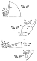
- a pair of spaced apart hinge arms 24 (only one is illustrated) are pivotly mounted on a pair of bracket members 22 (only one is illustrated) for movement about a transverse axis 26 (Figs. 1 and 2) between a stowed configuration as depicted in Fig. 3A and a deployed configuration as depicted in Fig. 4A.
- a transverse axis 26 Figs. 1 and 2
- Mounting holes 28 are provided in an upper surface 30 of the hinge arm for attaching an operating structure 32 such as a communication antenna reflector.
- a pair of torsional springs 34 are mounted on opposite side of the bracket member 22. One end of each spring is embedded in the structure of the bracket member while the opposite end is suitably engaged with the hinge arm 24. The springs 34 operate in concert to rapidly move the hinge arm 24 from the stowed (Fig. 3A) position to the deployed (Fig. 4A) position.
- a latch arm 36 is pivotly mounted on the bracket member 22 at a location distant from the transverse axis 26.
- a roller follower 38 is engaged with a contoured surface 40 of a cam 42 which is integrally mounted on the hinge arm 24.
- the roller follower 38 is biased into engagement with the contoured surface 40 by means of a pair of springs 44 (Fig. 2).
- the roller follower 38 advances along the contoured surface as depicted in Fig. 3B to an extreme position, as depicted in Fig. 4B.
- the roller follower 38 is received in a locking recess 46 which defines the deployed position of the hinge arm and prevents further movement of the hinge arm relative to the bracket member 22.
- deployment hinge apparatus 20 served its intended purpose well, it was in attempt to improve upon that construction that the present invention has been developed.
- self-latching deployment hinge apparatus 50 includes a stationary U-shaped bracket member 52 which is defined by a base 54 and a pair of upstanding parallel sidewalls 56 which are integral with the base.
- each hinge arm 58 Integral with each hinge arm 58 is a deployment and latching cam 64 which has a contoured surface 66 which extends to a nose member 68 which projects from an extremity of the cam.
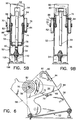
- a pair of axially aligned pins 70 (Fig. 5B) are fixed, respectively, to the opposed sidewalls 56 and project both inwardly and outwardly from the sidewalls.
- a pair of latch arms 72, 74 extend from the pins 70 to opposite ends which are joined by a cross bar 76.
- the latch arms 72, 74 are mutually parallel and each is formed with a slot 78 at its proximal end for slidable reception on the pins 70.
- a cam roller follower 80 is journaled on the cross bar 76 so as to be freely rotatable therein.
- a pair of resilient biasing members are provided for rapidly moving the hinge arm 24 from the stowed to the deployed position.
- These resilient biasing members are illustrated as being torsion springs 82, 84 externally mounted on opposite sides of the sidewalls 56. While torsion springs are disclosed, it will be appreciated that other forms of resilient biasing means may also be appropriate for the task to be performed.
- each of the springs 82, 84 is fixed to its associated pin 70 and an outer end is suitably attached to a drive pin 86 which is integral with each of the latch arms 72, 74 and projects outwardly through an arcuate slot 88 suitably located in each associated sidewalls 56.
- the bracket 52 At a location distant from its base 54, the bracket 52 includes a flange 90 which extends across and is integral with the sidewalls 56.
- the flange 90 is shaped to define a retention recess 92 which generally faces the base 54 of the bracket member 52.
- roller guide cam 94 which is coplanar with the cam roller follower 80 but is out-of-plane with respect to the deployment and latching cam 64. This relationship can be most clearly seen in Fig. 5B. Viewing Fig. 5A, the roller guide cam 94 is formed with a peak 96 and adjacent ascending and descending slopes, 98, 100, respectively, all being in the path of the cam roller follower 80. The descending slope 100 is immediately in communication with the retention recess 92.
- the torsion springs 82, 84 mounted on the bracket member 52 serve to rotate the hinge arm 58 and its associated deployment and latching cam 64 about the hinge bearing 62 in a counterclockwise direction, viewing Fig. 5A.
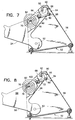
- Fig. 6 illustrates a partially deployed orientation of the hinge arm 58 and cam 64.
- the nose member 68 proceeds into the retention recess 92 as the roller follower 80 moves into engagement with the ascending slope 98 of the roller guide cam 94.
- Figs. 9A and 9B With continued rotation of the hinge arm 58 and of the cam 64, the position illustrated in Figs. 9A and 9B is reached at which the cam roller follower 80 is wedged in the retention recess 92 between the nose member 68 and the descending slope 100 of the roller guide cam 94.
- the orientation of the slot defined by the nose member 68 and descending slope 100 is designed to assure that reverse motion of the hinge arm 58 is ineffective to release it from its latched position. Indeed, only by manually reversing the travel of the latch arms 72, 74 until the relative position of components as illustrated in Fig. 7 is reached, can unlatching be achieved.
- the bracket member 52 is secured to a mounting panel 104 of a spacecraft or satellite. This may be achieved, for example, by means of a pair of fixed mounts defined by a pair of fasteners 106 and associated mounting flanges 108 integral with the bracket member 52.
- the base 54 of the bracket member 52 may be attached to the mounting panel 104 by means of an adjustable stud 110.
- the orientation of the operating structure 60 can be finely adjusted about an axis generally parallel that of the hinge bearing 62.
- Such simplified deployment hinge apparatus generally indicated by the reference numeral 120 includes a stationary bracket member 122 (Fig. 17) which may be fabricated from any suitable material although a particularly desirable construction would use graphite epoxy faceskins 122A with an aluminum honeycomb core 122B.
- a hinge arm 124 (Fig. 18) serves to support an operating structure 126 which, as in the previous embodiment, may be a communication antenna reflector.
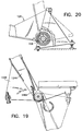
- the hinge arm 124 which may be fabricated from graphite epoxy composite material or from any other suitable material, is pivotly mounted on the stationary bracket member 122 by means of a suitable bearing 128 (see especially Figs. 12 and 16) including a housing 130 mounted by means of fasteners 132 to the bracket member 122.
- the bearing 128 also includes a self-aligning spherical member 134 having a central bore 136 therethrough whose axis is generally transverse to a plane of the bracket member 122.
- a removable hinge pin 138 is slidably received within the central bore 136 and extends a sufficient distance laterally from both sides of the stationary bracket member 122 so as to pivotly receive thereon mounting holes 140 at a near end of the hinge arm 124.
- the hinge pin 138 is suitably fixed, as by key 139 (Fig. 13), to the hinge arm 124 so that the two components move in unison.
- a rotary damper 142 may be operably mounted to an end of the hinge pin 138 to slow down the deployment rate of the hinge arm 124 on the bracket member 122 and to prevent high deployment loads from occurring between those components.
- a flex coupling 144 is desirable to assure that the self aligning capability of the bearing 128 will not be compromised. That self aligning capability assures that potential misalignment of a pair of hinges due to mounting to the operating structure will not cause the shaft 138 to bind.
- Stationary bracket member 122 may be mounted to a space craft or satellite 123 by means of fixed mounting flanges 122A and suitable fasteners (not shown). Adjustment of the bracket member relative to the space craft or satellite 123 may be achieved in the manner of the earlier described embodiment or by some other suitable alternative construction.
- a resilient member serves to bias the hinge arm 124 toward the deployed position illustrated by solid lines in Fig. 10 from the stowed position illustrated by dash-dot lines.
- a leaf spring 146 comprised of one or more leafs is secured at one end to the bearing housing 130 by means of suitable bolts 148 (see especially Fig. 15). Spaced from its attachment location, the leaf spring 146 is engaged by a roller 150 which is rotatably supported by opposed bearings 152 mounted on sidewalls of the hinge arm 124.
- the stationary bracket member 122 is formed with a first stop member 154 which is aligned with a second stop member 156 on the hinge arm 124 distant from the bearing 128.
- the stop member 156 is aligned to engage the first stop member 154 when the hinge arm 124 is in the fully deployed position.
- the hinge arm 124 is free to rotate on the bearing 128 with the leaf spring 146 providing the necessary energy to pivot the hinge 124 from the stowed to the deployed position.
- the roller 150 in engagement with the leaf spring 146 is caused to roll along the surface of the leaf spring minimizing friction and, therefore, wear between those components.
- the roller 150 is caused to move relative to the leaf spring 146, from an end thereof to a location mid way between the ends thereof.
- the leaf spring 146 is a preferred energy expedient for driving the hinge arm 124 between the stowed and deployed positions.
- a leaf spring 146A is capable of moving a hinge arm 124A through a deployment angle of approximately 180° relative to a stationary bracket member 122B.
- An initial position is depicted by solid lines, a final position by dash-dot lines.
- a torsion spring 158 may be employed for this purpose.
- the manner of mounting the deployment hinge apparatus 120 to the spacecraft or satellite 123 may be adjustable in the manner of the preceding embodiment, as noted above.
- the second stop member 156 may be a bolt whose head 160 is adjustable in a suitable manner, as by screwing, to thereby effect a desired change of orientation of the finally deployed position of the operating structure 126 about the axis defined by the hinge pin 138.
- Benefits achieved by the deployment hinge apparatus 120 include its simplicity and low cost as well as its versatility by reason of its broad range of deployment angles which are achievable with its use. It has a high deployment torque margin with low deployment loads due to use of a damper. High stiffness and light weight are achievable by use of composite materials and the apparatus experiences no backlash after its deployment.
Landscapes
- Engineering & Computer Science (AREA)
- Remote Sensing (AREA)
- Physics & Mathematics (AREA)
- Astronomy & Astrophysics (AREA)
- General Physics & Mathematics (AREA)
- Aviation & Aerospace Engineering (AREA)
- Mechanical Engineering (AREA)
- Aerials With Secondary Devices (AREA)
- Pivots And Pivotal Connections (AREA)
- Details Of Aerials (AREA)
Priority Applications (1)
| Application Number | Priority Date | Filing Date | Title |
|---|---|---|---|
| EP97200219A EP0776826B1 (de) | 1994-09-28 | 1995-09-26 | Entfaltungsgelenksvorrichtung |
Applications Claiming Priority (2)
| Application Number | Priority Date | Filing Date | Title |
|---|---|---|---|
| US08/314,068 US5673459A (en) | 1994-09-28 | 1994-09-28 | Deployment hinge apparatus |
| US314068 | 1994-09-28 |
Related Child Applications (1)
| Application Number | Title | Priority Date | Filing Date |
|---|---|---|---|
| EP97200219A Division EP0776826B1 (de) | 1994-09-28 | 1995-09-26 | Entfaltungsgelenksvorrichtung |
Publications (3)
| Publication Number | Publication Date |
|---|---|
| EP0704373A2 true EP0704373A2 (de) | 1996-04-03 |
| EP0704373A3 EP0704373A3 (de) | 1996-07-31 |
| EP0704373B1 EP0704373B1 (de) | 2000-01-19 |
Family
ID=23218419
Family Applications (2)
| Application Number | Title | Priority Date | Filing Date |
|---|---|---|---|
| EP95306759A Expired - Lifetime EP0704373B1 (de) | 1994-09-28 | 1995-09-26 | Entfaltungsgelenkvorrichtung |
| EP97200219A Expired - Lifetime EP0776826B1 (de) | 1994-09-28 | 1995-09-26 | Entfaltungsgelenksvorrichtung |
Family Applications After (1)
| Application Number | Title | Priority Date | Filing Date |
|---|---|---|---|
| EP97200219A Expired - Lifetime EP0776826B1 (de) | 1994-09-28 | 1995-09-26 | Entfaltungsgelenksvorrichtung |
Country Status (4)
| Country | Link |
|---|---|
| US (1) | US5673459A (de) |
| EP (2) | EP0704373B1 (de) |
| CA (1) | CA2157963A1 (de) |
| DE (2) | DE69514601T2 (de) |
Cited By (4)
| Publication number | Priority date | Publication date | Assignee | Title |
|---|---|---|---|---|
| FR2756620A1 (fr) * | 1996-11-30 | 1998-06-05 | Daimler Benz Aerospace Ag | Articulation pour le deploiement et le verrouillage d'un panneau solaire ou d'un reflecteur |
| EP1067623A3 (de) * | 1999-07-01 | 2002-07-31 | TRW Inc. | Entfalten eines Doppelreflektorsystems |
| FR2937800A1 (fr) * | 2008-10-24 | 2010-04-30 | Thales Sa | Antenne a longue focale, compacte, robuste et testable au sol, montee sur satellite |
| CN115432210A (zh) * | 2021-12-24 | 2022-12-06 | 哈工大机器人创新中心有限公司 | 一种齿轮传动分步式舱盖翻转锁止机构及其翻转锁止方法 |
Families Citing this family (35)
| Publication number | Priority date | Publication date | Assignee | Title |
|---|---|---|---|---|
| DE19518400A1 (de) * | 1995-05-19 | 1996-11-21 | Friedrich Fischer | Vorrichtung zur Kraftspeicherung in Federspeichern |
| DE19610297C1 (de) * | 1996-03-15 | 1997-01-23 | Daimler Benz Aerospace Ag | Vorrichtung zum Entfalten von zwei Paneelen für Solargeneratoren |
| US5921357A (en) * | 1997-04-14 | 1999-07-13 | Trw Inc. | Spacecraft deployment mechanism damper |
| US5927808A (en) * | 1997-08-29 | 1999-07-27 | Lear Corporation | Tumble seat for an automotive vehicle including improved seat cushion mounting structure |
| US6038738A (en) * | 1998-02-13 | 2000-03-21 | Chrysler Corporation | Hinge assembly |
| US6010096A (en) | 1998-07-22 | 2000-01-04 | Space Systems/Loral, Inc. | Deployment restraint and sequencing device |
| US6424314B1 (en) | 2001-05-16 | 2002-07-23 | Space Systems/Loral, Inc. | Four axis boom for mounting reflector on satellite |
| JP3953770B2 (ja) * | 2001-10-11 | 2007-08-08 | 株式会社ニフコ | 開閉部材の制動機構、これを備えた容器ホルダー及び自動車用扉 |
| US7024728B2 (en) | 2002-02-11 | 2006-04-11 | Advantage Manufacturing Corp. | End cap for multi bar linkage hinge assembly |
| US7089626B2 (en) * | 2004-02-12 | 2006-08-15 | Ford Motor Company | Adjustable door hinge |
| EP1735213B1 (de) * | 2004-04-08 | 2015-03-11 | Astrium Limited | Entfaltbarer ausleger |
| US7168668B2 (en) * | 2004-08-04 | 2007-01-30 | Checkpoint Systems, Inc. | Damage resistant antenna mount |
| US7275285B1 (en) * | 2004-11-15 | 2007-10-02 | Lockheed Martin Corporation | Deployment hinge |
| US7444714B2 (en) * | 2005-09-12 | 2008-11-04 | Prairie Valley Mfg Inc. | Automatic corral gate closure |
| US7644890B2 (en) * | 2006-06-01 | 2010-01-12 | Utah State University | Low-energy locking hinge mechanism for deployable devices |
| FR2902765B1 (fr) * | 2006-06-27 | 2008-08-29 | Alcatel Sa | Dispositif de positionnement en rotation a grande duree de vie pour applications spatiales |
| FR2903387B1 (fr) * | 2006-07-05 | 2008-08-29 | Alcatel Sa | Actionneur pour systemes de guidage d'equipements spatiaux a taux de rotation variable |
| JP5177569B2 (ja) * | 2009-08-27 | 2013-04-03 | キャタピラー エス エー アール エル | ヒンジおよびドア装置 |
| US8130168B1 (en) * | 2009-10-13 | 2012-03-06 | Pds Electronics, Inc. | Apparatus for raising and lowering an antena |
| US20130142602A1 (en) * | 2011-12-05 | 2013-06-06 | Robbey Barnts | Folding Mechanism and Power Supply for Lift Mounted to Vehicle |
| CN104743136B (zh) * | 2015-03-03 | 2016-08-24 | 北京空间机电研究所 | 一种展开锁定机构 |
| US10532830B2 (en) * | 2016-06-09 | 2020-01-14 | The Boeing Company | Stackable pancake satellite |
| US10435182B1 (en) * | 2016-09-12 | 2019-10-08 | Space Systems/Loral, Llc | Articulation techniques for a spacecraft solar array |
| CN107600461B (zh) * | 2017-07-31 | 2020-04-28 | 上海宇航系统工程研究所 | 一种滑动牵引装置 |
| US10957986B2 (en) | 2017-08-04 | 2021-03-23 | Space Systems/Loral, Llc | Reconfigurable spacecraft with a hold-down assembly for a rigid reflector |
| DE202017106061U1 (de) * | 2017-10-06 | 2017-10-30 | S-Fasteners Gmbh | Scharnier mit spannbarer Flach-Spiralfeder |
| DE202017106060U1 (de) * | 2017-10-06 | 2017-12-01 | S-Fasteners Gmbh | Scharnier mit spannbarem Federelement |
| WO2019116340A1 (en) * | 2017-12-14 | 2019-06-20 | Indian Institute Of Science | A variable torque hinge mechanism |
| CN111717420B (zh) * | 2020-07-21 | 2023-08-22 | 哈尔滨工业大学 | 压紧机构精准限位展开装置及展开限位方法 |
| CN115352654A (zh) * | 2022-08-05 | 2022-11-18 | 哈尔滨工业大学(威海) | 一种分离式返回器用姿态调整推进舱 |
| US12347937B2 (en) * | 2023-05-30 | 2025-07-01 | Eagle Technology, Llc | Spaceborne antenna with rolling flex hinges and associated methods |
| US12600497B2 (en) | 2023-07-17 | 2026-04-14 | Maxar Space Llc | Linked spacecraft dispensing |
| US12214909B1 (en) | 2023-07-17 | 2025-02-04 | Maxar Space Llc | Dispensing hinge assembly |
| US20250192429A1 (en) * | 2023-12-07 | 2025-06-12 | Macdonald, Dettwiler And Associates Corporation | Systems and methods for holding and releasing a large antenna reflector |
| CN119460169B (zh) * | 2025-01-15 | 2025-05-13 | 苏州馥昶空间技术有限公司 | 展开机构锁定装置 |
Citations (5)
| Publication number | Priority date | Publication date | Assignee | Title |
|---|---|---|---|---|
| US3587999A (en) | 1967-03-31 | 1971-06-28 | Sud Aviat Soc Nationale De Con | Articulation device for deployable appurtenances on spacecraft |
| US4290168A (en) | 1979-10-15 | 1981-09-22 | Rca Corporation | Hinge construction with positive locking means |
| US4780726A (en) | 1984-12-03 | 1988-10-25 | Trw Inc. | Depolyable reflector |
| US4880188A (en) | 1988-02-11 | 1989-11-14 | Messerschmitt-Boelkow-Blohm Gmbh | Joint for unfolding panels of a solar collector |
| US5037043A (en) | 1989-08-24 | 1991-08-06 | Messerschmitt-Boelkow-Blohm | Locking arrangement for unfolded solar generators |
Family Cites Families (12)
| Publication number | Priority date | Publication date | Assignee | Title |
|---|---|---|---|---|
| US3295809A (en) * | 1963-06-11 | 1967-01-03 | James F Smola | Torsion spring hinge mechanism |
| DE3215434C2 (de) * | 1982-04-24 | 1985-11-07 | Messerschmitt-Bölkow-Blohm GmbH, 8000 München | Riegelmechanismus für entfaltbare Solargeneratoren von Satelliten |
| DE3215431C2 (de) * | 1982-04-24 | 1985-11-07 | Messerschmitt-Bölkow-Blohm GmbH, 8012 Ottobrunn | Einrichtung zum Entfalten von Solargeneratoren |
| US4578919A (en) * | 1982-07-14 | 1986-04-01 | Harris Corporation | Self-stowing arrangement for structural tension members with taper latch hinge coupling joints |
| FR2531032A1 (fr) * | 1982-07-30 | 1984-02-03 | Aerospatiale | Dispositif de derivation d'effort temporaire pour maintien en position de stockage d'un appendice deployable pour vehicule spatial |
| US4561614A (en) * | 1982-12-07 | 1985-12-31 | Rca Corporation | Deployable folded multi-element satellite subsystems |
| DE3417413A1 (de) * | 1984-05-11 | 1985-11-14 | Dr. Karl Thomae Gmbh, 7950 Biberach | Dicarbonsaeure-monohydrazid-derivate, ihre herstellung und ihre verwendung als kopplungskomponenten |
| IT1222756B (it) * | 1987-09-29 | 1990-09-12 | Contraves Italiana Spa | Meccanismo di articolazione piana a moto diretto e inverso privo di attuatori di movimento elettrici,per applicazioni spaziali |
| JPH0755679B2 (ja) * | 1987-12-25 | 1995-06-14 | 宇宙開発事業団 | 展開ラツチ機構 |
| JPH0211498A (ja) * | 1988-06-29 | 1990-01-16 | Natl Space Dev Agency Japan<Nasda> | 展開ラツチ機構 |
| US5310144A (en) * | 1992-07-06 | 1994-05-10 | Hughes Aircraft Company | Method and apparatus for satellite torque balancing |
| DE4337968C2 (de) * | 1992-11-10 | 1994-09-08 | Deutsche Aerospace | Gelenk zum Entfalten und Verriegeln von Raumfahrtelementen |
-
1994
- 1994-09-28 US US08/314,068 patent/US5673459A/en not_active Expired - Lifetime
-
1995
- 1995-09-11 CA CA002157963A patent/CA2157963A1/en not_active Abandoned
- 1995-09-26 DE DE69514601T patent/DE69514601T2/de not_active Expired - Fee Related
- 1995-09-26 EP EP95306759A patent/EP0704373B1/de not_active Expired - Lifetime
- 1995-09-26 EP EP97200219A patent/EP0776826B1/de not_active Expired - Lifetime
- 1995-09-26 DE DE69517589T patent/DE69517589T2/de not_active Expired - Fee Related
Patent Citations (5)
| Publication number | Priority date | Publication date | Assignee | Title |
|---|---|---|---|---|
| US3587999A (en) | 1967-03-31 | 1971-06-28 | Sud Aviat Soc Nationale De Con | Articulation device for deployable appurtenances on spacecraft |
| US4290168A (en) | 1979-10-15 | 1981-09-22 | Rca Corporation | Hinge construction with positive locking means |
| US4780726A (en) | 1984-12-03 | 1988-10-25 | Trw Inc. | Depolyable reflector |
| US4880188A (en) | 1988-02-11 | 1989-11-14 | Messerschmitt-Boelkow-Blohm Gmbh | Joint for unfolding panels of a solar collector |
| US5037043A (en) | 1989-08-24 | 1991-08-06 | Messerschmitt-Boelkow-Blohm | Locking arrangement for unfolded solar generators |
Cited By (8)
| Publication number | Priority date | Publication date | Assignee | Title |
|---|---|---|---|---|
| FR2756620A1 (fr) * | 1996-11-30 | 1998-06-05 | Daimler Benz Aerospace Ag | Articulation pour le deploiement et le verrouillage d'un panneau solaire ou d'un reflecteur |
| US5911536A (en) * | 1996-11-30 | 1999-06-15 | Daimler-Benz Aerospace Ag | Joint for deploying and locking a solar panel or a reflection |
| EP1067623A3 (de) * | 1999-07-01 | 2002-07-31 | TRW Inc. | Entfalten eines Doppelreflektorsystems |
| FR2937800A1 (fr) * | 2008-10-24 | 2010-04-30 | Thales Sa | Antenne a longue focale, compacte, robuste et testable au sol, montee sur satellite |
| EP2190059A1 (de) * | 2008-10-24 | 2010-05-26 | Thales | Kompakte und robuste Antenne mit langer Brennweite, zur Prüfung auf der Prüfbank und Einbau in einem Satellit |
| US8487830B2 (en) | 2008-10-24 | 2013-07-16 | Thales | Antenna with long focal length that is compact, robust and can be tested on the ground, mounted on a satellite |
| CN115432210A (zh) * | 2021-12-24 | 2022-12-06 | 哈工大机器人创新中心有限公司 | 一种齿轮传动分步式舱盖翻转锁止机构及其翻转锁止方法 |
| CN115432210B (zh) * | 2021-12-24 | 2023-03-31 | 哈工大机器人创新中心有限公司 | 一种齿轮传动分步式舱盖翻转锁止机构及其翻转锁止方法 |
Also Published As
| Publication number | Publication date |
|---|---|
| US5673459A (en) | 1997-10-07 |
| DE69517589D1 (de) | 2000-07-27 |
| DE69514601T2 (de) | 2000-06-08 |
| EP0776826B1 (de) | 2000-06-21 |
| EP0704373A3 (de) | 1996-07-31 |
| CA2157963A1 (en) | 1996-03-29 |
| EP0704373B1 (de) | 2000-01-19 |
| EP0776826A3 (de) | 1997-08-27 |
| DE69517589T2 (de) | 2001-03-08 |
| EP0776826A2 (de) | 1997-06-04 |
| DE69514601D1 (de) | 2000-02-24 |
Similar Documents
| Publication | Publication Date | Title |
|---|---|---|
| US5673459A (en) | Deployment hinge apparatus | |
| US6010096A (en) | Deployment restraint and sequencing device | |
| US4880188A (en) | Joint for unfolding panels of a solar collector | |
| US5600868A (en) | Deployment hinge | |
| US5356095A (en) | Attenuating linged deployment apparatus | |
| US6478261B2 (en) | Spacecraft with deployable panel array | |
| US6092264A (en) | Single axis fold actuator and lock for member | |
| US6817062B2 (en) | Door hinge apparatus having a door checking function | |
| US8347747B2 (en) | Strain energy shuttle apparatus and method | |
| US4290168A (en) | Hinge construction with positive locking means | |
| US20190017308A1 (en) | Integrated stowage bin assembly | |
| JPH0996161A (ja) | ケーブル・テンション装置 | |
| WO1995009290A1 (en) | Hinge and check assembly | |
| JP2019502601A (ja) | ヒンジ | |
| US6158088A (en) | Deployable hinge assembly providing end of travel damping | |
| US5479678A (en) | Locking hinge | |
| US5845530A (en) | Cam and roller overcenter handle mechanism | |
| US7644890B2 (en) | Low-energy locking hinge mechanism for deployable devices | |
| GB2052618A (en) | Hinge and hold-open assembly | |
| CN217421847U (zh) | 一种楔块式铰链展开机构 | |
| CN114458684B (zh) | 一种铰链机构 | |
| US5594521A (en) | Brake apparatus for a shutter | |
| CN115637903B (zh) | 立方星太阳翼锁链及立方星帆板 | |
| US4654671A (en) | Self-aligning torque transmitting hinge | |
| US5082212A (en) | Torque limiter device and deployable lengthening piece of a space instrument equipped with this device |
Legal Events
| Date | Code | Title | Description |
|---|---|---|---|
| PUAI | Public reference made under article 153(3) epc to a published international application that has entered the european phase |
Free format text: ORIGINAL CODE: 0009012 |
|
| AK | Designated contracting states |
Kind code of ref document: A2 Designated state(s): DE FR GB IT |
|
| PUAL | Search report despatched |
Free format text: ORIGINAL CODE: 0009013 |
|
| AK | Designated contracting states |
Kind code of ref document: A3 Designated state(s): DE FR GB IT |
|
| 17P | Request for examination filed |
Effective date: 19961025 |
|
| 17Q | First examination report despatched |
Effective date: 19980604 |
|
| GRAG | Despatch of communication of intention to grant |
Free format text: ORIGINAL CODE: EPIDOS AGRA |
|
| GRAG | Despatch of communication of intention to grant |
Free format text: ORIGINAL CODE: EPIDOS AGRA |
|
| GRAH | Despatch of communication of intention to grant a patent |
Free format text: ORIGINAL CODE: EPIDOS IGRA |
|
| GRAH | Despatch of communication of intention to grant a patent |
Free format text: ORIGINAL CODE: EPIDOS IGRA |
|
| GRAA | (expected) grant |
Free format text: ORIGINAL CODE: 0009210 |
|
| DX | Miscellaneous (deleted) | ||
| AK | Designated contracting states |
Kind code of ref document: B1 Designated state(s): DE FR GB IT |
|
| REF | Corresponds to: |
Ref document number: 69514601 Country of ref document: DE Date of ref document: 20000224 |
|
| ET | Fr: translation filed | ||
| RAP4 | Party data changed (patent owner data changed or rights of a patent transferred) |
Owner name: SPACE SYSTEMS / LORAL, INC. |
|
| ITF | It: translation for a ep patent filed | ||
| PLBE | No opposition filed within time limit |
Free format text: ORIGINAL CODE: 0009261 |
|
| STAA | Information on the status of an ep patent application or granted ep patent |
Free format text: STATUS: NO OPPOSITION FILED WITHIN TIME LIMIT |
|
| 26N | No opposition filed | ||
| REG | Reference to a national code |
Ref country code: GB Ref legal event code: IF02 |
|
| PGFP | Annual fee paid to national office [announced via postgrant information from national office to epo] |
Ref country code: FR Payment date: 20020830 Year of fee payment: 8 |
|
| PGFP | Annual fee paid to national office [announced via postgrant information from national office to epo] |
Ref country code: GB Payment date: 20020918 Year of fee payment: 8 |
|
| PGFP | Annual fee paid to national office [announced via postgrant information from national office to epo] |
Ref country code: DE Payment date: 20020930 Year of fee payment: 8 |
|
| PG25 | Lapsed in a contracting state [announced via postgrant information from national office to epo] |
Ref country code: GB Free format text: LAPSE BECAUSE OF NON-PAYMENT OF DUE FEES Effective date: 20030926 |
|
| PG25 | Lapsed in a contracting state [announced via postgrant information from national office to epo] |
Ref country code: DE Free format text: LAPSE BECAUSE OF NON-PAYMENT OF DUE FEES Effective date: 20040401 |
|
| GBPC | Gb: european patent ceased through non-payment of renewal fee |
Effective date: 20030926 |
|
| PG25 | Lapsed in a contracting state [announced via postgrant information from national office to epo] |
Ref country code: FR Free format text: LAPSE BECAUSE OF NON-PAYMENT OF DUE FEES Effective date: 20040528 |
|
| REG | Reference to a national code |
Ref country code: FR Ref legal event code: ST |
|
| PG25 | Lapsed in a contracting state [announced via postgrant information from national office to epo] |
Ref country code: IT Free format text: LAPSE BECAUSE OF NON-PAYMENT OF DUE FEES;WARNING: LAPSES OF ITALIAN PATENTS WITH EFFECTIVE DATE BEFORE 2007 MAY HAVE OCCURRED AT ANY TIME BEFORE 2007. THE CORRECT EFFECTIVE DATE MAY BE DIFFERENT FROM THE ONE RECORDED. Effective date: 20050926 |