EP0704566A1 - Halbautomatische Nähanlage - Google Patents
Halbautomatische Nähanlage Download PDFInfo
- Publication number
- EP0704566A1 EP0704566A1 EP95306775A EP95306775A EP0704566A1 EP 0704566 A1 EP0704566 A1 EP 0704566A1 EP 95306775 A EP95306775 A EP 95306775A EP 95306775 A EP95306775 A EP 95306775A EP 0704566 A1 EP0704566 A1 EP 0704566A1
- Authority
- EP
- European Patent Office
- Prior art keywords
- die plate
- workpiece
- sewing
- leading edge
- edge
- Prior art date
- Legal status (The legal status is an assumption and is not a legal conclusion. Google has not performed a legal analysis and makes no representation as to the accuracy of the status listed.)
- Withdrawn
Links
Images

Classifications
-
- D—TEXTILES; PAPER
- D06—TREATMENT OF TEXTILES OR THE LIKE; LAUNDERING; FLEXIBLE MATERIALS NOT OTHERWISE PROVIDED FOR
- D06F—LAUNDERING, DRYING, IRONING, PRESSING OR FOLDING TEXTILE ARTICLES
- D06F71/00—Apparatus for hot-pressing clothes, linen or other textile articles, i.e. wherein there is substantially no relative movement between pressing element and article while pressure is being applied to the article; Similar machines for cold-pressing clothes, linen or other textile articles
- D06F71/18—Apparatus for hot-pressing clothes, linen or other textile articles, i.e. wherein there is substantially no relative movement between pressing element and article while pressure is being applied to the article; Similar machines for cold-pressing clothes, linen or other textile articles specially adapted for pressing particular garments or parts thereof
- D06F71/22—Apparatus for hot-pressing clothes, linen or other textile articles, i.e. wherein there is substantially no relative movement between pressing element and article while pressure is being applied to the article; Similar machines for cold-pressing clothes, linen or other textile articles specially adapted for pressing particular garments or parts thereof for pressing collars
-
- D—TEXTILES; PAPER
- D05—SEWING; EMBROIDERING; TUFTING
- D05B—SEWING
- D05B35/00—Work-feeding or -handling elements not otherwise provided for
- D05B35/02—Work-feeding or -handling elements not otherwise provided for for facilitating seaming; Hem-turning elements; Hemmers
- D05B35/04—Work-feeding or -handling elements not otherwise provided for for facilitating seaming; Hem-turning elements; Hemmers with movable tools
-
- D—TEXTILES; PAPER
- D05—SEWING; EMBROIDERING; TUFTING
- D05B—SEWING
- D05B81/00—Sewing machines incorporating devices serving purposes other than sewing, e.g. for blowing air, for grinding
Definitions
- This invention relates to a work station where sewing operations are conducted on a textile workpiece.
- Cuff, collar and pocket flap running and top stitching machines have become quite similar because the operations are quite similar.
- Exemplary state of the art cuff and collar machines offered by applicant's assignee are found in U.S. Patents 4,841,887 and 5,421,278, the disclosures of which are incorporated herein by reference. These machines comprise a smooth horizontal table, a work holder where a textile workpiece is positioned by a worker and manipulated by the holder, a sewing machine, a transfer arm that moves to the work holder, pushes the workpiece against the table, slides the workpiece to the sewing machine and then moves the workpiece around under the sewing needle as stitching occurs and a digital controller for energizing all of the components of the device at the correct times. It is this type device that this invention most nearly relates.
- a fabric workpiece is first prepared by juxtaposing a front, a back and a backing.
- a generally U-shaped seam is sewn in a running operation to leave a central pocket and one unstitched edge.
- the shape of the workpiece, the seam and the pocket depend on whether the workpiece is going to be a cuff, a pocket flap or a collar and on the particular design desired in the end product.
- the fabric workpiece is trimmed, turned inside-out and pressed in one operation and top stitched in a second separate operation.
- the workpiece is trimmed at the corner because, when it is inverted, there is normally too much material in the corner causing the finished workpiece to appeared puckered.
- Special purpose machines are used to trim, invert and press cuff, pocket flap and collar workpieces such as Model DS515D from Bou-Yue Manufacturing Co., Ltd. of Taiwan.
- Top stitching is very similar to running because the stitching is along generally the same path.
- the textile workpiece is taken from the inverter/presser, placed in a guide and smoothed down by the worker and the transfer arm moves the workpiece from the guide to the sewing station.
- the separate operation at the inverter/presser is omitted, at least for cuffs and pocket flaps.
- the operator inverts the workpiece and slips it onto a die plate located above the stainless steel table so the die plate extends into the pocket of the workpiece.
- the die plate is expanded to stretch the material.
- the worker manipulates the workpiece to place the seam along or slightly under the edge of the die plate. This seam is the central section of the stitching and, in a cuff, corresponds to the leading edge of the material that encircles the wrist.
- a support is moved upwardly into engagement with the bottom of the die plate to hold the workpiece in position.
- the die plate and support are moved downwardly into engagement with the table.
- An edge former is advanced into engagement with the seamed edge of the workpiece and thus juxtaposes the edge of the die plate. This pushes the leading edge of the workpiece slightly under the leading edge of the die plate.
- a presser on the edge former moves downwardly into engagement with the workpiece.
- the edge former and/or presser are more-or-less continuously heated with an electric heater so the leading edge of the workpiece is held in its desired position, heated and pressed.
- the transfer arm moves over the workpiece and pushes the workpiece downwardly against the table top.
- the presser is raised.
- the die plate and edge former/presser are retracted away from the workpiece.
- the transfer arm slides the workpiece to the sewing needle and moves the workpiece in a desired path so the desired pattern is stitched onto the workpiece. While sewing is occurring, the worker is putting the next workpiece on the die plate and the process is repeated.
- This technique has substantial advantages because it eliminates a special purpose machine to prepare fabric workpieces for top stitching and eliminates the effort running the special purpose machine.
- Those skilled in the art realize the labor content of shirts has fallen to a range of $1.50-9.00/shirt and that further cost reductions are difficult.
- the elimination of a conventional work station and its cost of operation with no reduction in throughput of subsequent operations is highly significant.
- Another object of this invention is to provide an improved technique which eliminates a series of steps leading up to a top stitching operation.
- a further object of this invention is to provide an improved machine which incorporates many of the steps of preparing a workpiece for a top stitching operation into the top stitching operation.
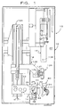
- a top stitch machine 10 of this invention comprises, as major components, a work table 12, a holder 14 for receiving and manipulating fabric workpieces, a sewing head 16, means 18 for sliding the fabric blanks from the holder 14 toward the sewing head 16 and a digital controller (not shown) for energizing the various components of the machine 10 at the appropriate times.
- the work table 12 includes a smooth planar table section 20 which is stainless steel or the like so it remains smooth for a substantial period.
- the holder 14 comprises a cast support 22 mounted on pins 24 and providing a pair of pins 26 mounting a die plate assembly 28 for vertical movement relative to the table 12.
- An air cylinder 30 moves the die plate assembly 28 vertically on command from a lower position adjacent the table top 20 to an elevated position.
- the die plate assembly 28 includes a base 32 comprising a stationary section 34 and a movable section 36 mounted for movement by a gross adjusting device 38 to adjust the spacing between the sections 34, 36 and thereby alter the size of the workpiece received on the die plate 40.
- the adjusting device 38 may be of any suitable type.
- the die plate 40 comprises a section 42 rigid with the section 34 and a movable section 44 guided on and movable relative to the movable section 36.
- An air cylinder 46 includes an abutment 48 affixed to the stationary die plate section 34 and a lug 50 extending through a slot 52 into engagement with the movable die plate section 44.
- a fabric workpiece 54 comprises a front panel 56, a back panel 58 and one or more backing panels 60 that have been stitched together in a running operation to provide a generally U-shaped seam 62 providing a central seam section 64 and a pair of end seam sections 66.
- the workpiece 54 accordingly provides a central pocket 68.
- the workpiece 54 will be incorporated into a shirt as a cuff. Similar workpieces that will become pocket flaps and collars may also be used in this invention.
- the adjusting device 38 allows the die plate 40 to be adjusted so accommodate workpieces 54 of different size. It is thus quite convenient to change the holder 14 from making one size shirt to a larger size shirt.
- the operator With the air cylinder 46 retracted, the operator places the central pocket 68 of the workpiece 54 onto the die plate 40. The air cylinder 46 is then extended thereby tightening the workpiece on the die plate 40. The operator adjusts the fabric of the workpiece 54 on the die plate 40 so the central seam section 64 lies slightly under the leading edge of the die plate 40.
- the exact shape of the die plate sections 42, 44 are changed depending on the shape of the workpiece. The die plate sections 42, 44 are thus removable and can be replaced as desired.
- a support 70 is mounted under the die plate 40 for movement between a retracted position generally planar with the table top 20 to an extended position abutting the die plate 40 for holding the fabric workpiece 54 in place after the operator has adjusted the workpiece 54 to position the seam 64 in an appropriate manner.
- the support 70 comprises a long narrow plate 72 received, in the retracted position, in a slot 74 in the table top 20.
- An air cylinder 76 comprises one or more rods 78 of sufficient length to elevate the plate 72 to abut the die plate 40 in its elevated position.
- the die plate assembly 28 and the support 70 are simultaneously lowered to captivate the lower half of the workpiece 54 against the table top 20.
- the support 70 may be mounted for movement horizontally away from the leading edge of the die plate 40 for snugly pulling the central seam 64 of the workpiece 54 under the leading edge of the die plate 40.
- the work holder 14 also includes a clamp 80 comprising a base 82 mounted in a slot 84 for horizontal movement toward and away from a work area 86 under the die plate 40.
- An air cylinder 88 is accordingly provided to move the base 82 from an extended position adjacent the work area 86 to a retracted position away from the work area.
- the base 82 includes a bottom plate 90 from which extend a pair of pins 92.
- the clamp 80 includes an edge former 94 comprising a plate 96 having openings 98 receiving the pins 92 therein.
- the plate 96 provides a recess 100 shaped to closely receive the leading edge of the workpiece 54.
- the recess 100 provides a chamfered edge 102 which pushes the fabric workpiece 54, adjacent the seam section 64, under the die plate 40 as the base 82 is moved from its retracted position toward the extended position adjacent the work area 86.
- the edge former 94 also acts as a base for a presser 104 and accordingly includes a pair of upstanding pins 106.
- the presser 104 includes a pair of spaced bosses providing openings 108 receiving the pins 106 and mounting the presser 104 for vertical movement in response to actuation of an air cylinder 110.
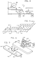
- the presser 104 includes a rib 112 shaped to match the edge of the workpiece 54. As shown best in Figure 5, the presser 104 extends beyond the end of the edge former 96 so the rib 112 is positioned to engage the workpiece 54 and push it against the die plate 40.
- the heating means 114 includes an electrical heating element 116 mounted in a groove 118 in the edge former 94 generally parallel to the long edge of the recess 100.
- the heating means 114 also includes a thermostat 120 and wiring 122 for energizing the heating element 116.
- the support 70 is raised to hold the workpiece 54 in position.
- the plate 72 does not extend to the edges of the die plate 40 so there is sufficient room for the fingers of the operator.
- the die plate assembly 28 and the support 70 are simultaneously lowered to their lower position.
- the clamp 80 is then advanced on command by the cylinder 88 so the edge 102 further pushes the seam 64 under the leading edge of the die plate 40. Because the recess 100 closely receives the die plate 40, it will be seen that the entire forward edge of the workpiece 54 is tucked under the die plate 40.
- the presser 104 is then lowered by the cylinder 110 into engagement with the edge of the workpiece 54 thereby pushing the workpiece 54 against the die plate 40. This smoothes the workpiece 54 and, in cooperation with the heat applied by the heating means 114, irons or presses the workpiece so it will stay in position during sewing.
- the transfer means 18 includes an x-y positioner 124 having a transfer arm 126 receiving a transfer clamp 128 configured in the shape of the workpiece 54.
- the transfer arm 126 includes a pair of upstanding pins 130 receiving the transfer clamp 128 for vertical movement between a position elevated above the table top 20 and a position pushing the workpiece 54 against the table top 20 in response to a force applied by an air cylinder 132.
- the transfer clamp 128 is removable from the transfer arm 126 to accommodate workpieces 54 of different configuration.
- the function of the transfer means 18 is to slide the workpiece 54 from the work holder 14 to the sewing head 16.
- the transfer clamp 128 is sized to be received in a recess 134 provided by the presser 104.
- a command from the digital controller causes the x-y positioner 124 to move the transfer clamp 128 horizontally to a position immediately above the recess 134 in the die plate 40.
- the cylinder 132 lowers the transfer clamp 128 through the recess 134 into engagement with the workpiece 54 and pushes the workpiece 54 gently against the table top 20.
- the presser 104 is raised by the cylinder 110 out of engagement with the workpiece 54.
- the clamp 80 is retracted horizontally by the cylinder 88.
- the die plate 40 is retracted in the direction of the arrow 136 ( Figure 2) so the die plate 40 moves out of the central pocket 68.
- the x-y positioner 124 then moves the transfer arm 126 so the workpiece 54 slides along the work area 86 in a path toward the sewing needle 138 of the sewing head 16.
- the x-y positioner 124 slides the workpiece 54 in a desired path so the stitch pattern creates the top stitching desired on the workpiece 54.
- the work holder 14 avoids the use of an inverting and pressing operation separate from the top stitching operation and accordingly provides substantial economies without loss of throughput.
Landscapes
- Engineering & Computer Science (AREA)
- Textile Engineering (AREA)
- Sewing Machines And Sewing (AREA)
Applications Claiming Priority (2)
| Application Number | Priority Date | Filing Date | Title |
|---|---|---|---|
| US313366 | 1994-09-27 | ||
| US08/313,366 US5493981A (en) | 1994-09-27 | 1994-09-27 | Semi-automatic top stitcher with die plate and movable support |
Publications (1)
| Publication Number | Publication Date |
|---|---|
| EP0704566A1 true EP0704566A1 (de) | 1996-04-03 |
Family
ID=23215434
Family Applications (1)
| Application Number | Title | Priority Date | Filing Date |
|---|---|---|---|
| EP95306775A Withdrawn EP0704566A1 (de) | 1994-09-27 | 1995-09-26 | Halbautomatische Nähanlage |
Country Status (2)
| Country | Link |
|---|---|
| US (1) | US5493981A (de) |
| EP (1) | EP0704566A1 (de) |
Cited By (1)
| Publication number | Priority date | Publication date | Assignee | Title |
|---|---|---|---|---|
| US11865057B2 (en) | 2019-04-29 | 2024-01-09 | Abram's Nation, Llc | Portable confinement device |
Families Citing this family (2)
| Publication number | Priority date | Publication date | Assignee | Title |
|---|---|---|---|---|
| US5584258A (en) * | 1994-12-23 | 1996-12-17 | Ideal Equipment Company, Ltd. | Semi-automatic pocket and pocket flap setter |
| US5996198A (en) * | 1998-02-25 | 1999-12-07 | Wang; Cherng-Fa | Apparatus for ribbing cloth venetian blind strips |
Citations (9)
| Publication number | Priority date | Publication date | Assignee | Title |
|---|---|---|---|---|
| US2917211A (en) * | 1958-03-10 | 1959-12-15 | Silverman Jacob | Pressing machine |
| US3170423A (en) * | 1961-04-24 | 1965-02-23 | Ernest M Junkins | Automatic guiding apparatus |
| US3568897A (en) * | 1969-12-15 | 1971-03-09 | Cluett Peabody & Co Inc | Method and apparatus for manufacturing garment parts |
| US3789781A (en) * | 1971-08-24 | 1974-02-05 | Blue Bell Inc | Sewing system |
| GB2034757A (en) * | 1978-10-04 | 1980-06-11 | Stahl Urban Co | Pressing garment parts |
| US4427139A (en) * | 1981-08-31 | 1984-01-24 | Capital-Mercury Shirt Corp. | Collar pressing method and apparatus |
| US4841887A (en) | 1988-09-27 | 1989-06-27 | Ideal Equipment Co., Ltd. | Semi-automatic sewing station |
| DE4008148A1 (de) * | 1989-03-14 | 1990-09-20 | Brother Ind Ltd | Naehgutfaltvorrichtung fuer eine naehmaschine |
| US5421278A (en) | 1993-10-05 | 1995-06-06 | Ideal Equipment Company, Ltd. | Semi-automated sewing station |
Family Cites Families (8)
| Publication number | Priority date | Publication date | Assignee | Title |
|---|---|---|---|---|
| BE636067A (de) * | 1962-09-05 | |||
| DE2449121A1 (de) * | 1974-10-16 | 1976-04-29 | Kochs Adler Ag | Hilfseinrichtung fuer die fertigung von mit aufgesetzten kragen versehenen oberhemden oder blusen |
| GB1526209A (en) * | 1974-12-23 | 1978-09-27 | Secretary Industry Brit | Automatic stitching machines |
| DE3512358A1 (de) * | 1985-04-04 | 1986-10-09 | Kochs Adler Ag, 4800 Bielefeld | Naehguthalter zum naehen des spitzenbereichs von krawatten |
| JPH0666Y2 (ja) * | 1986-12-01 | 1994-01-05 | ブラザー工業株式会社 | 加工布保持装置 |
| DE3730406A1 (de) * | 1987-09-10 | 1989-03-23 | Kochs Adler Ag | Verfahren und vorrichtung zum annaehen eines kragens an einen rumpf eines bekleidungsstuecks |
| JPH03192485A (ja) * | 1989-12-22 | 1991-08-22 | Citizen Watch Co Ltd | 認識信号発生手段付きマイコンic |
| DE4029891C1 (de) * | 1990-09-21 | 1992-02-27 | Duerkopp Adler Ag, 4800 Bielefeld, De |
-
1994
- 1994-09-27 US US08/313,366 patent/US5493981A/en not_active Expired - Fee Related
-
1995
- 1995-09-26 EP EP95306775A patent/EP0704566A1/de not_active Withdrawn
Patent Citations (9)
| Publication number | Priority date | Publication date | Assignee | Title |
|---|---|---|---|---|
| US2917211A (en) * | 1958-03-10 | 1959-12-15 | Silverman Jacob | Pressing machine |
| US3170423A (en) * | 1961-04-24 | 1965-02-23 | Ernest M Junkins | Automatic guiding apparatus |
| US3568897A (en) * | 1969-12-15 | 1971-03-09 | Cluett Peabody & Co Inc | Method and apparatus for manufacturing garment parts |
| US3789781A (en) * | 1971-08-24 | 1974-02-05 | Blue Bell Inc | Sewing system |
| GB2034757A (en) * | 1978-10-04 | 1980-06-11 | Stahl Urban Co | Pressing garment parts |
| US4427139A (en) * | 1981-08-31 | 1984-01-24 | Capital-Mercury Shirt Corp. | Collar pressing method and apparatus |
| US4841887A (en) | 1988-09-27 | 1989-06-27 | Ideal Equipment Co., Ltd. | Semi-automatic sewing station |
| DE4008148A1 (de) * | 1989-03-14 | 1990-09-20 | Brother Ind Ltd | Naehgutfaltvorrichtung fuer eine naehmaschine |
| US5421278A (en) | 1993-10-05 | 1995-06-06 | Ideal Equipment Company, Ltd. | Semi-automated sewing station |
Cited By (1)
| Publication number | Priority date | Publication date | Assignee | Title |
|---|---|---|---|---|
| US11865057B2 (en) | 2019-04-29 | 2024-01-09 | Abram's Nation, Llc | Portable confinement device |
Also Published As
| Publication number | Publication date |
|---|---|
| US5493981A (en) | 1996-02-27 |
Similar Documents
| Publication | Publication Date | Title |
|---|---|---|
| WO2018040298A1 (zh) | 自动衬衫袖叉机 | |
| US4445631A (en) | Patch pocket-forming, folding and setting apparatus | |
| CN211394883U (zh) | 一种激光开袋装置 | |
| US4463697A (en) | Method and device for producing a pocket on a workpiece | |
| US5584258A (en) | Semi-automatic pocket and pocket flap setter | |
| US5016549A (en) | Attaching a strip of cloth with a zip-fastener component to a trouser forepart | |
| US5493981A (en) | Semi-automatic top stitcher with die plate and movable support | |
| HU180824B (en) | Shoe industrial sewing-machine for compacting cut pieces particularly moccasin ones by means of flange seam | |
| JPH0311797B2 (de) | ||
| US4901657A (en) | Multifunction sewing machine with tape feeding, cutting and hemming apparatus | |
| US3483834A (en) | Stitching of materials | |
| JPH0686882A (ja) | ミシンにおける布地保持装置と基布搬送装置 | |
| CN206941141U (zh) | 一种织带的缝纫压脚机构 | |
| JPH0262273B2 (de) | ||
| EP0491056A1 (de) | Nähverfahren und vorrichtung | |
| US4079681A (en) | Device for the insertion of the pocket strip applied to sewing machines for making welted pockets | |
| US4314516A (en) | Workpiece guide for sewing machines | |
| US4991527A (en) | Method of attaching a strip of cloth with a zip-fastener component to a trouser forepart | |
| US6390002B1 (en) | Sewing unit for sewing folded or pre-folded pockets | |
| US4573421A (en) | Sewing machine device for making garments with pleats | |
| US2811121A (en) | Method of making a multi-ply one-piece collar | |
| EP0361640A1 (de) | Halbautomatische Nähanlage | |
| JPH11235488A (ja) | ポケットセッターにおける折込み装置 | |
| US4223815A (en) | Post form stay inserter for shirt collars | |
| CN224047675U (zh) | 一种自动开袋机的快拆结构 |
Legal Events
| Date | Code | Title | Description |
|---|---|---|---|
| PUAI | Public reference made under article 153(3) epc to a published international application that has entered the european phase |
Free format text: ORIGINAL CODE: 0009012 |
|
| AK | Designated contracting states |
Kind code of ref document: A1 Designated state(s): DE ES FR GB IT |
|
| 17P | Request for examination filed |
Effective date: 19960612 |
|
| 17Q | First examination report despatched |
Effective date: 19971002 |
|
| STAA | Information on the status of an ep patent application or granted ep patent |
Free format text: STATUS: THE APPLICATION IS DEEMED TO BE WITHDRAWN |
|
| 18D | Application deemed to be withdrawn |
Effective date: 19980213 |