EP0704581A2 - Mécanisme de soupape - Google Patents
Mécanisme de soupape Download PDFInfo
- Publication number
- EP0704581A2 EP0704581A2 EP95114481A EP95114481A EP0704581A2 EP 0704581 A2 EP0704581 A2 EP 0704581A2 EP 95114481 A EP95114481 A EP 95114481A EP 95114481 A EP95114481 A EP 95114481A EP 0704581 A2 EP0704581 A2 EP 0704581A2
- Authority
- EP
- European Patent Office
- Prior art keywords
- cistern
- flush
- actuator
- float
- water
- Prior art date
- Legal status (The legal status is an assumption and is not a legal conclusion. Google has not performed a legal analysis and makes no representation as to the accuracy of the status listed.)
- Withdrawn
Links
- 230000007246 mechanism Effects 0.000 title claims abstract description 46
- XLYOFNOQVPJJNP-UHFFFAOYSA-N water Substances O XLYOFNOQVPJJNP-UHFFFAOYSA-N 0.000 claims abstract description 89
- 230000000630 rising effect Effects 0.000 claims abstract 2
- 230000033001 locomotion Effects 0.000 claims description 7
- 238000000034 method Methods 0.000 claims description 7
- 230000004044 response Effects 0.000 claims description 5
- 230000003247 decreasing effect Effects 0.000 claims 1
- 230000005484 gravity Effects 0.000 claims 1
- 230000009471 action Effects 0.000 description 7
- 230000009977 dual effect Effects 0.000 description 5
- 238000011010 flushing procedure Methods 0.000 description 5
- 230000000994 depressogenic effect Effects 0.000 description 4
- 230000000694 effects Effects 0.000 description 2
- 238000012423 maintenance Methods 0.000 description 2
- 230000004048 modification Effects 0.000 description 2
- 238000012986 modification Methods 0.000 description 2
- 206010063659 Aversion Diseases 0.000 description 1
- 230000005791 algae growth Effects 0.000 description 1
- 238000013459 approach Methods 0.000 description 1
- 230000008901 benefit Effects 0.000 description 1
- 230000033228 biological regulation Effects 0.000 description 1
- 238000010276 construction Methods 0.000 description 1
- 230000007423 decrease Effects 0.000 description 1
- 230000000977 initiatory effect Effects 0.000 description 1
- ZRHANBBTXQZFSP-UHFFFAOYSA-M potassium;4-amino-3,5,6-trichloropyridine-2-carboxylate Chemical compound [K+].NC1=C(Cl)C(Cl)=NC(C([O-])=O)=C1Cl ZRHANBBTXQZFSP-UHFFFAOYSA-M 0.000 description 1
- 239000002243 precursor Substances 0.000 description 1
- 230000001105 regulatory effect Effects 0.000 description 1
- 230000003252 repetitive effect Effects 0.000 description 1
- 238000007493 shaping process Methods 0.000 description 1
- 239000002699 waste material Substances 0.000 description 1
Images


Classifications
-
- E—FIXED CONSTRUCTIONS
- E03—WATER SUPPLY; SEWERAGE
- E03D—WATER-CLOSETS OR URINALS WITH FLUSHING DEVICES; FLUSHING VALVES THEREFOR
- E03D1/00—Water flushing devices with cisterns ; Setting up a range of flushing devices or water-closets; Combinations of several flushing devices
-
- E—FIXED CONSTRUCTIONS
- E03—WATER SUPPLY; SEWERAGE
- E03D—WATER-CLOSETS OR URINALS WITH FLUSHING DEVICES; FLUSHING VALVES THEREFOR
- E03D1/00—Water flushing devices with cisterns ; Setting up a range of flushing devices or water-closets; Combinations of several flushing devices
- E03D1/30—Valves for high or low level cisterns; Their arrangement ; Flushing mechanisms in the cistern, optionally with provisions for a pre-or a post- flushing and for cutting off the flushing mechanism in case of leakage
- E03D1/36—Associated working of inlet and outlet valves
-
- F—MECHANICAL ENGINEERING; LIGHTING; HEATING; WEAPONS; BLASTING
- F16—ENGINEERING ELEMENTS AND UNITS; GENERAL MEASURES FOR PRODUCING AND MAINTAINING EFFECTIVE FUNCTIONING OF MACHINES OR INSTALLATIONS; THERMAL INSULATION IN GENERAL
- F16K—VALVES; TAPS; COCKS; ACTUATING-FLOATS; DEVICES FOR VENTING OR AERATING
- F16K31/00—Actuating devices; Operating means; Releasing devices
- F16K31/12—Actuating devices; Operating means; Releasing devices actuated by fluid
- F16K31/18—Actuating devices; Operating means; Releasing devices actuated by fluid actuated by a float
- F16K31/20—Actuating devices; Operating means; Releasing devices actuated by fluid actuated by a float actuating a lift valve
- F16K31/24—Actuating devices; Operating means; Releasing devices actuated by fluid actuated by a float actuating a lift valve with a transmission with parts linked together from a single float to a single valve
Definitions
- the present invention relates to cisterns and, in particular, to cisterns having a flush valve.
- Cisterns can be conveniently categorised into two types.
- One type of cistern has a flush valve located in its base which is used to block the flush pipe which connects the cistern to the pan.
- the flush valve is analogous to the plug in a sink or basin which is full of water. When the flush valve is operated, this is equivalent to the plug being removed, and the water in the cistern flows through the flush valve and down the flush pipe.
- the other type of cistern is the syphonic cistern in which the flush pipe is connected with the interior of the cistern via an inverted U-shaped passage which at its highest point passes above the maximum water level in the cistern.
- the U-shaped passage In order for such a cistern to be flushed it is necessary for the U-shaped passage to be filled with water and thereby induce a syphonic action within the passage which syphons the water from the cistern into the flush pipe.
- the cistern incorporating the flush valve suffers from the problem that the flush valve, particularly after a number of years of service, may commence leaking. Such leaking can be brought about because of a number of reasons such as algae growth on the valve, debris which has been introduced into the cistern via the inlet pipe becoming lodged in the flush valve, the perishing of rubber components of the flush valve, and the like. Normally such leaking is not catastrophic, instead there is a trickle of water down the flush pipe and into the lavatory pan.
- All cisterns must be provided with a re-filling mechanism which normally takes the form of an inlet valve connected a mains water supply in which the water is under pressure, and a level detecting arrangement which opens the inlet valve when the water level within the cistern drops, and closes the inlet valve when the water level within the cistern rises to its predetermined "full" height or level.
- the level detecting arrangement is almost universally a float which is connected to the inlet valve by means of a pivoting float arm.
- this object is achieved by the realisation that once an inlet valve has operated at the cessation of a flush to refill a cistern, if that inlet valve can be disabled until the next flush is required, then if the flush valve should happen to leak, then the maximum volume of water which can be wasted is the volume of water contained within the cistern.
- the disablement of the inlet valve be removed if the cistern is to be flushed. This has the consequence that in the event that there is a leaking flush valve and the cistern is empty at the time that the next flush is required, then the person operating the flush actuator of the cistern observes that no flush is immediately forthcoming yet hears the cistern being refilled. Accordingly, a short time after the first actuation of the flush actuator, the flush actuator can be re-actuated and a flush provided. Thus, although the pan is able to be flushed thereby overcoming any sanitary problem, a clear message that the cistern is not operating normally is given to the user.
- a first aspect of the present invention discloses an interlock mechanism for a flush valve operated cistern having a flush valve in the base thereof which, when opened, drains water stored in said cistern to constitute a flush, said cistern further having an actuator mechanism interconnecting a flush actuator with said flush valve to open the latter on operation of said actuator, and an inlet valve having a refill actuator operable in response to the level of water in said cistern to refill same to a predetermined level; said interlock mechanism comprising a latch means interconnected with said refill actuator and said flush actuator and operable to prevent refilling of said cistern, said latch means being releasable by operation of said flush actuator and being re-settable by initial re-filling of said cistern after a flush.
- a flush valve operated cistern having a flush valve in the base thereof which, when opened, drains water in said cistern to constitute a flush
- said cistern further having an actuator mechanism interconnecting a flush actuator with said flush valve to open the latter on operation of said actuator, and an inlet valve having a refill actuator operable in response to the level of water in said cistern to refill same to a predetermined level; said method comprising the steps of
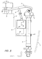
- FIG. 1 A first form of the first basic embodiment of the present invention will now be described with reference to Figs. 1 to 3.
- the cistern 1 is connected to a flush pipe (not illustrated) by a threaded spigot 2 which is normally closed by means of a flush valve 3.
- the cistern is provided with an inlet stem 4 at the top of which is located an inlet valve 5 and on which is reciprocally mounted a float 6.
- the float 6 is connected to the inlet valve 5 by means of a float arm 7 and adjustable linkage 8.
- the float arm 7 includes a projection 9 which extends underneath a pair of flush actuator buttons 10 which surmount a flush mechanism 11.
- the flush mechanism 11 is substantially conventional, and is of the general dual flush type described in Australian Patent No. 597,438 (to which US Patent No. 4,882,793 corresponds).
- the inlet valve 5 is of the hydraulic type described in Australian Patent Application No. 72899/94 (previously Application No. PM 1316) and is interconnected to the float arm by means of a rack and pinion arrangement described in Australian Patent Application No. PM 8030. All three of the above referenced patent and patent applications are in the name of the present applicant and the disclosure thereof is hereby incorporated into the present specification by cross reference.
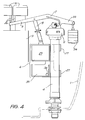
- FIG. 2 some detail of the internal mechanism of the inlet valve 5 can be seen.
- the inlet valve 5 is supplied with water under mains pressure from an inlet 15 which is surrounded by a concentric outlet 16 which leads into the cistern 1.
- a bulbous chamber 17 At the upper end of the inlet 15 is a bulbous chamber 17 in which is positioned an egg-like body 18 mounted at the lower end of a spindle 19.
- the spindle 19 is able to be vertically reciprocated by means of a rack 20 and part pinion 21.
- the chamber 17 has an opening 23 which is able to be occluded by the body 18 and thus forms the valve seat.
- the opening 23 leads via U-shaped passages 24 into the outlet 16.
- the body 18 occludes the opening 23 and the inlet valve 5 is therefore closed.
- the part pinion 21 is rotated in a clockwise direction therefore driving the spindle 19 downwardly and opening the valve 5.
- a balance of flow induced pressure forces is created on the body 18 thereby holding the inlet valve 5 open until the float arm 7 is raised. This is essentially achieved by means of the float 6 in order to close the inlet valve 5.
- the balance of hydraulic forces means that the net force required to be exerted on the spindle 19 is relatively low.
- each of the flush actuator buttons 10 carries a lug 26 which abuts the float arm 7 in its raised, cistern full, position illustrated in Fig. 3.
- the corresponding lug 26 moves the float arm 7 downwardly as seen in Fig. 3. This has the effect of opening the inlet valve 5 simultaneously with the raising of the flush valve 3 brought about by the operation of the flush mechanism 11 in response to the actuation of either one of the flush buttons 10.
- the float 6 begins a descent down the stem 4 since it is supported only by the buoyant force of the falling level of water within the cistern.
- the float has two cylindrical guides 27 and a shallow bucket 28 which is located below the float chamber 29.
- the float chamber 29 includes two holes 30 and 31.
- the bucket 28 is full of water and the float chamber 29 is full of water up to the level of the upper hole 31.
- the float 6 is relatively heavy and as the water drops within the cistern the weight of water within the bucket 28 and float chamber 29 helps drive the float 6 downwardly along the stem 4.
- water is passing out through the hole 30 so that as the cistern empties, water within the float chamber 29 has dropped to the level of the lower hole 30.
- the cistern commences refilling and the float 6 is at its lowermost position.
- the float 6 rises, however, its speed of rise is reduced or braked by the weight of water present in the bucket 28.
- the inlet valve 5 closes slowly thereby substantially preventing water hammer.
- the float 6 When the cistern has refilled, the float 6 returns to its original position in which the float chamber 29 is full of water up to the level of the upper hole 31 and the flushing cycle is ready to recommence. Above the upper hole 31 is entrapped air which maintains an upwardly directed buoyant force on the float arm 7. This aids the water pressure force on the body 18 which keeps the inlet valve 5 closed.
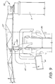
- Fig. 4 a variation of the first basic arrangement described in Figs. 1 to 3 is illustrated. Essentially the arrangement is as before save that the float arm 7 includes an extension 33 from which hangs a counterweight 34.
- the float chamber 29 is empty and airtight and in place of the shallow bucket 28 a large bucket 35 is provided having a drain hole 36.
- the bucket 35 As the cistern 1 empties, so too does the bucket 35, the water draining therefrom via the drain hole 36. As a consequence, when the float 6 has reached its lowermost position, the bucket 35 is substantially empty. As the cistern re-fills, the bucket 35 is substantially buoyant and this, together with the counterweight 34, is sufficient to enable the float 6 to rise together with the water level in the cistern. As a consequence, the flush cycle is completed and the cistern is re-set. Again the filling bucket 38 brakes the rise of the float 6.
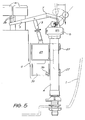
- FIG. 5 a still further variation of the basic arrangement of Figs. 1 to 3 is illustrated. This variation is essentially the same as in Fig. 4 save that the hanging weight 34 is replaced by a counterweight 134 which is rigidly mounted on the float arm 7.
- the weight of the counterweight 134 assists the fall of the float 6 bearing in mind that the bucket 35 is being progressively drained, and hence lightened in weight, via hole 36.
- the weight of the counterweight 134 in the over-centre position slows the rise of the float during cistern re-filling. This keeps the valve 5 open to a larger extent for a longer time and thus decreases the filling time.
- cistern 1 has a flush valve 3, and inlet stem 4, flush actuator buttons 10 and flush mechanism 11 substantially as before.
- a conventional inlet valve 50 mounted atop the inlet stem 4 is a conventional inlet valve 50 having a conventional float arm 57 and float 56.
- the flush valve 3 is provided with a hollow rectangular float stem 38, the lower portion of which is illustrated in Fig. 6 and the upper portion of which is illustrated in Fig. 7.
- the hollow float stem 38 functions as an overflow tube in conventional manner.
- Straddling the flush mechanism 11 and passing over the top of the float stem 38 is a saddle 40 on which is pivoted a downwardly directed cup 41.
- the cup 41 is pivoted on the saddle 40 by means of an L-shaped arm 42.
- an erect upstand 43 Secured to the saddle 40 is an erect upstand 43 which includes a lip 44 which provides a flat surface or step.
- Pivoted from the float arm 57 is a pendulous stay 45 which includes a notch 46 towards its middle and a ramp 47 at its lower end.
- the fall and subsequent rise of water within the cistern 1 means that the downwardly directed cup 41 which functions as a float permits the L-shaped arm 42 to firstly pivot in a clockwise direction as the water level falls, and then pivot in an anti-clockwise direction as the water level rises. Since the stay 45 and lip 44 of the upstand 43 are disengaged during this period, the movement of the L-shaped arm 42 is of no effect.
Landscapes
- Engineering & Computer Science (AREA)
- General Engineering & Computer Science (AREA)
- Life Sciences & Earth Sciences (AREA)
- Hydrology & Water Resources (AREA)
- Public Health (AREA)
- Water Supply & Treatment (AREA)
- Health & Medical Sciences (AREA)
- Mechanical Engineering (AREA)
- Sanitary Device For Flush Toilet (AREA)
- Float Valves (AREA)
- External Artificial Organs (AREA)
- Centrifugal Separators (AREA)
- Gas Separation By Absorption (AREA)
- Valve-Gear Or Valve Arrangements (AREA)
Priority Applications (1)
| Application Number | Priority Date | Filing Date | Title |
|---|---|---|---|
| EP96119551A EP0764744B1 (fr) | 1994-09-29 | 1995-09-14 | Mécanisme de soupape d'alimentation |
Applications Claiming Priority (2)
| Application Number | Priority Date | Filing Date | Title |
|---|---|---|---|
| AUPM8494A AUPM849494A0 (en) | 1994-09-29 | 1994-09-29 | An inlet valve mechanism |
| AUPM0084/94 | 1994-09-29 |
Related Child Applications (1)
| Application Number | Title | Priority Date | Filing Date |
|---|---|---|---|
| EP96119551A Division EP0764744B1 (fr) | 1994-09-29 | 1995-09-14 | Mécanisme de soupape d'alimentation |
Publications (2)
| Publication Number | Publication Date |
|---|---|
| EP0704581A2 true EP0704581A2 (fr) | 1996-04-03 |
| EP0704581A3 EP0704581A3 (fr) | 1996-06-19 |
Family
ID=3783013
Family Applications (2)
| Application Number | Title | Priority Date | Filing Date |
|---|---|---|---|
| EP96119551A Expired - Lifetime EP0764744B1 (fr) | 1994-09-29 | 1995-09-14 | Mécanisme de soupape d'alimentation |
| EP95114481A Withdrawn EP0704581A3 (fr) | 1994-09-29 | 1995-09-14 | Mécanisme de soupape |
Family Applications Before (1)
| Application Number | Title | Priority Date | Filing Date |
|---|---|---|---|
| EP96119551A Expired - Lifetime EP0764744B1 (fr) | 1994-09-29 | 1995-09-14 | Mécanisme de soupape d'alimentation |
Country Status (10)
| Country | Link |
|---|---|
| EP (2) | EP0764744B1 (fr) |
| JP (1) | JP3744982B2 (fr) |
| CN (1) | CN1127822A (fr) |
| AT (1) | ATE176941T1 (fr) |
| AU (1) | AUPM849494A0 (fr) |
| DE (1) | DE69507951T2 (fr) |
| IN (1) | IN184278B (fr) |
| MY (1) | MY116370A (fr) |
| NZ (1) | NZ272984A (fr) |
| TW (1) | TW298607B (fr) |
Cited By (6)
| Publication number | Priority date | Publication date | Assignee | Title |
|---|---|---|---|---|
| WO1999040264A1 (fr) | 1998-02-05 | 1999-08-12 | Bereznai Jozsef | Ensemble citerne pour toilettes a chasse d'eau |
| GB2349682A (en) * | 1999-05-04 | 2000-11-08 | Diaz Perez Clorindo | Inlet valve for tanks and cisterns |
| WO2006094331A1 (fr) * | 2005-03-10 | 2006-09-14 | Caroma Industries Limited | Ensemble de soupape d’entree de reservoir de chasse d’eau |
| FR2899917A1 (fr) * | 2006-04-14 | 2007-10-19 | Valentin Sas Soc Par Actions S | Dispositif de chasse d'eau positionne dans un reservoir |
| CN107524209A (zh) * | 2017-10-09 | 2017-12-29 | 杨建军 | 一种节水型冲厕水箱 |
| WO2024213860A1 (fr) * | 2023-04-11 | 2024-10-17 | Aquatech2O Ltd | Appareil de chasse d'eau |
Families Citing this family (10)
| Publication number | Priority date | Publication date | Assignee | Title |
|---|---|---|---|---|
| JP2009235804A (ja) * | 2008-03-27 | 2009-10-15 | Toto Ltd | 水洗便器のタンク構造 |
| ES2353475B1 (es) * | 2008-04-25 | 2012-03-16 | Fominaya, S.A. | Grifo para llenado de depósitos de inodoros o similares. |
| KR101024365B1 (ko) * | 2009-03-31 | 2011-03-23 | 와토스코리아 주식회사 | 양변기 필밸브의 림측급수관 물량조절밸브 |
| FR2957098B1 (fr) * | 2010-03-02 | 2012-03-09 | Hubert Magar | Detection de fuite sur robinet de chasse d'eau |
| CN102561485B (zh) * | 2011-12-30 | 2013-10-30 | 虞吉伟 | 并联式双阀装置、便器及节水方法 |
| US9441354B2 (en) * | 2012-06-08 | 2016-09-13 | Lab (Xiamen)Sanitary Fittings Inc. | Water inlet valve |
| CN104154300B (zh) * | 2014-07-30 | 2016-05-11 | 攀钢集团西昌钢钒有限公司 | 容器自动补水或排水装置 |
| MX2017008946A (es) * | 2015-01-13 | 2018-03-23 | Wagienience Pty Ltd | Disposición de válvula de entrada para una cisterna de inodoro. |
| CN104631582B (zh) * | 2015-02-02 | 2017-01-18 | 厦门瑞尔特卫浴科技股份有限公司 | 一种水箱溢流报警方法和装置 |
| CN106638845B (zh) * | 2016-11-04 | 2022-06-24 | 中山市美图塑料工业有限公司 | 一种冲水阀及带有该冲水阀的智能座厕 |
Citations (3)
| Publication number | Priority date | Publication date | Assignee | Title |
|---|---|---|---|---|
| US4882793A (en) | 1986-10-20 | 1989-11-28 | Caroma Industries, Ltd. | Dual flush cistern mechanism |
| AU597438B2 (en) | 1986-10-20 | 1990-05-31 | Caroma Industries Limited | A dual flush cistern mechanism |
| AU7289994A (en) | 1993-09-20 | 1995-03-30 | Caroma Industries Limited | A hydraulic valve |
Family Cites Families (7)
| Publication number | Priority date | Publication date | Assignee | Title |
|---|---|---|---|---|
| DE364423C (de) * | 1922-11-29 | Josef Hellrung | Abtrittspuelkasten | |
| BE854840A (fr) * | 1977-05-20 | 1977-09-16 | Michel Hans | Dispositif automatique de fermeture de vanne a liquide a l'etat permanent et dispositif de deverrouillage pour remplissage de reservoirs |
| IT1166874B (it) * | 1979-06-11 | 1987-05-06 | Selman S D F Crespi Carlo E Fe | Dispositivo per la regolazione del livello dell'acqua particolarmente in una cassetta per apparecchi igienici |
| US4615056A (en) * | 1984-11-20 | 1986-10-07 | Max Rudman | Flushing cistern |
| US4843657A (en) * | 1987-09-17 | 1989-07-04 | Orr James W | Anti-flood toilet tank fill valve |
| US5211204A (en) * | 1991-06-14 | 1993-05-18 | Moen Incorporated | Toilet tank ballcock with detent arm |
| US5287882A (en) * | 1993-05-11 | 1994-02-22 | Moen Incorporated | Ball cock assembly float with drain openings |
-
1994
- 1994-09-29 AU AUPM8494A patent/AUPM849494A0/en not_active Abandoned
-
1995
- 1995-09-11 NZ NZ272984A patent/NZ272984A/en not_active IP Right Cessation
- 1995-09-13 MY MYPI95002718A patent/MY116370A/en unknown
- 1995-09-14 EP EP96119551A patent/EP0764744B1/fr not_active Expired - Lifetime
- 1995-09-14 DE DE69507951T patent/DE69507951T2/de not_active Expired - Fee Related
- 1995-09-14 AT AT96119551T patent/ATE176941T1/de not_active IP Right Cessation
- 1995-09-14 EP EP95114481A patent/EP0704581A3/fr not_active Withdrawn
- 1995-09-19 TW TW084109814A patent/TW298607B/zh active
- 1995-09-27 JP JP24943095A patent/JP3744982B2/ja not_active Expired - Fee Related
- 1995-09-28 IN IN1175CA1995 patent/IN184278B/en unknown
- 1995-09-29 CN CN95118668A patent/CN1127822A/zh active Pending
Patent Citations (3)
| Publication number | Priority date | Publication date | Assignee | Title |
|---|---|---|---|---|
| US4882793A (en) | 1986-10-20 | 1989-11-28 | Caroma Industries, Ltd. | Dual flush cistern mechanism |
| AU597438B2 (en) | 1986-10-20 | 1990-05-31 | Caroma Industries Limited | A dual flush cistern mechanism |
| AU7289994A (en) | 1993-09-20 | 1995-03-30 | Caroma Industries Limited | A hydraulic valve |
Cited By (6)
| Publication number | Priority date | Publication date | Assignee | Title |
|---|---|---|---|---|
| WO1999040264A1 (fr) | 1998-02-05 | 1999-08-12 | Bereznai Jozsef | Ensemble citerne pour toilettes a chasse d'eau |
| GB2349682A (en) * | 1999-05-04 | 2000-11-08 | Diaz Perez Clorindo | Inlet valve for tanks and cisterns |
| WO2006094331A1 (fr) * | 2005-03-10 | 2006-09-14 | Caroma Industries Limited | Ensemble de soupape d’entree de reservoir de chasse d’eau |
| FR2899917A1 (fr) * | 2006-04-14 | 2007-10-19 | Valentin Sas Soc Par Actions S | Dispositif de chasse d'eau positionne dans un reservoir |
| CN107524209A (zh) * | 2017-10-09 | 2017-12-29 | 杨建军 | 一种节水型冲厕水箱 |
| WO2024213860A1 (fr) * | 2023-04-11 | 2024-10-17 | Aquatech2O Ltd | Appareil de chasse d'eau |
Also Published As
| Publication number | Publication date |
|---|---|
| IN184278B (fr) | 2000-07-22 |
| JP3744982B2 (ja) | 2006-02-15 |
| EP0764744A2 (fr) | 1997-03-26 |
| CN1127822A (zh) | 1996-07-31 |
| AUPM849494A0 (en) | 1994-10-27 |
| EP0764744A3 (fr) | 1997-04-02 |
| DE69507951T2 (de) | 1999-08-26 |
| JPH08135838A (ja) | 1996-05-31 |
| MY116370A (en) | 2004-01-31 |
| EP0764744B1 (fr) | 1999-02-24 |
| NZ272984A (en) | 1998-01-26 |
| TW298607B (fr) | 1997-02-21 |
| DE69507951D1 (de) | 1999-04-01 |
| ATE176941T1 (de) | 1999-03-15 |
| EP0704581A3 (fr) | 1996-06-19 |
Similar Documents
| Publication | Publication Date | Title |
|---|---|---|
| US5742951A (en) | Inlet valve mechanism | |
| EP0704581A2 (fr) | Mécanisme de soupape | |
| US4651359A (en) | Dual mode flush valve assembly | |
| AU2006201757B2 (en) | Discharge valve for a flushing cistern | |
| US3890657A (en) | Chemical dispenser for toilet | |
| US3955218A (en) | Self-venting tank valve for toilet tanks | |
| US5287882A (en) | Ball cock assembly float with drain openings | |
| US5129110A (en) | Selectable toilet-water-level flushing system | |
| US5862537A (en) | Flush lever operated reservoir toilet tank control | |
| US5301375A (en) | Primer tank-checkvalve syphon toilet flushing apparatus | |
| WO2007139371A1 (fr) | Appareil de vanne | |
| US4171547A (en) | Toilet-blow flush system and devices therefor | |
| EP1703029A1 (fr) | Dispositif d'economie quantifiee de l'eau pour les toilettes, utilisant un mecanisme de double chasse | |
| AU687608B2 (en) | An inlet valve mechanism | |
| US5842236A (en) | Device for refilling and emptying lavatory flushing cisterns | |
| US20030000007A1 (en) | Dual volume discharge outlet valve apparatus | |
| US439630A (en) | Flushing-tank | |
| SE504888C2 (sv) | Spolsystem för WC-stolar | |
| WO1999020850A1 (fr) | Poussoir pour soupape d'aspiration d'un reservoir de chasse d'eau | |
| US755166A (en) | Flushing-tank. | |
| US8296871B2 (en) | Toilet water tank refilling system | |
| US4821766A (en) | Toilet tank fill valve | |
| US346261A (en) | boyle | |
| CA1285456C (fr) | Clapet de remplissage d'un reservoir de chasse d'eau | |
| HK1011395A1 (en) | An inlet valve mechanism |
Legal Events
| Date | Code | Title | Description |
|---|---|---|---|
| PUAI | Public reference made under article 153(3) epc to a published international application that has entered the european phase |
Free format text: ORIGINAL CODE: 0009012 |
|
| AK | Designated contracting states |
Kind code of ref document: A2 Designated state(s): AT BE CH DE DK ES FR GB GR IE IT LI LU MC NL PT SE |
|
| AX | Request for extension of the european patent |
Free format text: LT PAYMENT 950914;LV PAYMENT 950914;SI PAYMENT 950914 |
|
| RAX | Requested extension states of the european patent have changed |
Free format text: LT PAYMENT 950914;LV PAYMENT 950914;SI PAYMENT 950914 |
|
| PUAL | Search report despatched |
Free format text: ORIGINAL CODE: 0009013 |
|
| AK | Designated contracting states |
Kind code of ref document: A3 Designated state(s): AT BE CH DE DK ES FR GB GR IE IT LI LU MC NL PT SE |
|
| AX | Request for extension of the european patent |
Free format text: LT PAYMENT 950914;LV PAYMENT 950914;SI PAYMENT 950914 |
|
| STAA | Information on the status of an ep patent application or granted ep patent |
Free format text: STATUS: THE APPLICATION IS DEEMED TO BE WITHDRAWN |
|
| 18D | Application deemed to be withdrawn |
Effective date: 19961220 |