EP0704599A1 - Einrichtung für mit einer Elektro-Bohrlochpumpe ausgerüsteten Erdölbohrung - Google Patents
Einrichtung für mit einer Elektro-Bohrlochpumpe ausgerüsteten Erdölbohrung Download PDFInfo
- Publication number
- EP0704599A1 EP0704599A1 EP95402176A EP95402176A EP0704599A1 EP 0704599 A1 EP0704599 A1 EP 0704599A1 EP 95402176 A EP95402176 A EP 95402176A EP 95402176 A EP95402176 A EP 95402176A EP 0704599 A1 EP0704599 A1 EP 0704599A1
- Authority
- EP
- European Patent Office
- Prior art keywords
- well
- casing
- installation
- electric motor
- pump
- Prior art date
- Legal status (The legal status is an assumption and is not a legal conclusion. Google has not performed a legal analysis and makes no representation as to the accuracy of the status listed.)
- Granted
Links
Images

Classifications
-
- E—FIXED CONSTRUCTIONS
- E21—EARTH OR ROCK DRILLING; MINING
- E21B—EARTH OR ROCK DRILLING; OBTAINING OIL, GAS, WATER, SOLUBLE OR MELTABLE MATERIALS OR A SLURRY OF MINERALS FROM WELLS
- E21B43/00—Methods or apparatus for obtaining oil, gas, water, soluble or meltable materials or a slurry of minerals from wells
- E21B43/12—Methods or apparatus for controlling the flow of the obtained fluid to or in wells
- E21B43/121—Lifting well fluids
- E21B43/128—Adaptation of pump systems with down-hole electric drives
-
- F—MECHANICAL ENGINEERING; LIGHTING; HEATING; WEAPONS; BLASTING
- F04—POSITIVE - DISPLACEMENT MACHINES FOR LIQUIDS; PUMPS FOR LIQUIDS OR ELASTIC FLUIDS
- F04B—POSITIVE-DISPLACEMENT MACHINES FOR LIQUIDS; PUMPS
- F04B47/00—Pumps or pumping installations specially adapted for raising fluids from great depths, e.g. well pumps
- F04B47/06—Pumps or pumping installations specially adapted for raising fluids from great depths, e.g. well pumps having motor-pump units situated at great depth
Definitions
- the present invention relates to an installation for an oil well equipped with an electric pump at the bottom of a well.
- an assistance system or well activation system can be used.
- a pump at the lower end of a production tube located in the well. This pump can be driven by an electric motor immersed in the bottom of the well which is supplied by a cable arranged in the annular space between the casing and the casing of the well.
- the power range and installation depth require high voltages, up to 1000 to 3000 volts to minimize cable losses. But these high voltages make the installations vulnerable.
- a rod pumping installation consists of a volumetric bottom pump installed in the casing, the piston of which is driven in translation from the surface by means of steel or glass fiber rods. On the surface, the movement is given to the rod train by a balance structure driven by a rotary electric motor or a hydraulic cylinder.
- the dead weight, inertia, friction and mechanical fatigue of the rods limit the pumping capacity and performance of these systems. They are unsuitable for eruptive wells on which bottom safety devices are required, deep wells or high flows (greater than 200 m3 / d of liquid).
- the monobloc concept of the current bottom electric pumps is interesting in the case of wells where the handling operation is easy and inexpensive, in the case of drinking water wells, non-eruptive wells on land or shallow. It is not suitable for current and future oil wells. These are increasingly deep, inaccessible, dangerous (because often eruptive), and equipped with complex and delicate equipment to set up. he it becomes desirable to concentrate the essential weaknesses such as mechanical wear and tear on an independent module which would be lighter and less costly to reassemble and replace, with a cable or a winch for example.
- the present invention therefore relates to an installation for an oil well which makes it possible to separate the electrical part from the mechanical parts of an electric pump group immersed in the well, to place the electrical part in an enclosure sheltered from external aggressions originating in particular from effluent from the bottom of the well, and to group the mechanical parts in order to facilitate their removal.
- the invention provides an installation for an oil well extending from the surface to a layer of petroleum rock comprising a casing arranged in the well and forming a flow path towards the surface for hydrocarbons coming from the layer of petroleum rock, a casing delimiting the wall of the well, and a joint disposed at the bottom of the well between the casing and the casing so as to form a chamber isolated from hydrocarbons, the installation further comprising, in the well, a pump and a electric motor intended to actuate the pump characterized in that the stator of the electric motor is arranged outside the casing, isolated by the latter flowing hydrocarbons inside the casing.
- the electric motor can be a rotary or linear motor.
- the pump is placed upstream of the electric motor.
- the present invention has the advantage of creating an impermeable sealing barrier by the effluent between the central movable part and the stator windings.
- this barrier is a simpler and more reliable technology because it is a static barrier of the wall type, which is no longer crossed by a mobile part (shaft or rod) transmitting the movement to the mobile part of the pump.
- the movable part of the motor can be set up and removed independently of the fixed part, and in particular of the electrical equipment, and moreover thanks to a light intervention with the cable, which facilitates mechanical maintenance and reduces operating costs.
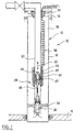
- FIG. 1 is shown, generally at 10, an installation for an oil well in which a well 12 extends between the surface 14 and a layer of oil-bearing rock 16.
- the well 12 has a casing 18 which makes the well tight in relation to to the rock layers crossed by the well.
- a production casing 20 between a well head, shown diagrammatically at 22, and a seal 24, more commonly known as a "packer” which is arranged, for example, about 100 m above the level of the petroleum rock 16.
- a sealed chamber 26 is defined between the outer wall of the casing 20 and the inner wall of the casing 18.
- the casing 20 comprises, at its lower end, a pumping assembly, generally represented at 28 which comprises a reciprocating pump 30 intended to be actuated in the direction of the arrow 32 by a linear electric motor 34 by l by means of a piston rod 36.
- the linear electric motor 34 is supplied from the surface 14 by an electric cable 38 placed in the chamber 26.
- the linear motor 34 comprises a stator 40 and a movable part 42 displaceable according to the effect of the magnetic field generated by the stator.
- the stator 40 is mounted outside the casing 20 inside the chamber 26.
- the casing 20, at least in the region 43 adjoining the linear motor 34, is formed of non-magnetic material, which, in a preferred example, is ceramic.
- the mobile part 42 is provided, at its upper end with a hooking head 44 which makes it possible to rise to the surface, for example by means of a cable, the mobile part 42 as well as the pump 30.
- the cooling of the motor is ensured by the extracted effluent which passes through the mechanical part of the motor, either by passing through the air gap between the mobile part and the stationary stator, or at the center of the mobile part, then hollowed out.
- the chamber 26 containing the electrical part can, in a preferred embodiment, receive a dielectric substance, a liquid or a gel, in order to further reinforce the durability of the installation.
- a gel also has the advantage of thermally insulating the tubing, which then receives all the heat dissipated in the cable 38 which runs along it and of which it serves as a radiator. This warm-up will ensure a better overall energy efficiency of the installation thanks to the heating of the flows.
- the pump 30 As shown in FIG. 1, it is preferable to place the pump 30 under the motor 34, which offers advantages for certain types of viscous or gaseous effluents in favor of the performance of the well. Indeed, the fact of placing the pump under the motor significantly reduces the pressure losses before the effluent enters the pump.
- the lubrication between the moving and fixed parts is done either dry with suitable materials (ceramic, zirconium, teflon, carbides or bronze), or by an effluent film put in place by hydrodynamic effect.
- suitable materials ceramic, zirconium, teflon, carbides or bronze
- a parallel lubrication system could also be implemented.
- the installation according to the invention avoids the electrical crossing of the seal or "packer" which was hitherto inevitable and constituted a source of the main electrical failures of the systems used until then.
- a second embodiment is shown in Figure 2 in which the elements common to the installation of Figure 1 bear the same reference numbers.
- a rotary motor generally represented at 46, is connected to a rotary pump of conventional construction, shown diagrammatically at 48, by a rod 50.
- the fixed part of the rotary motor 46, in particular the stator 52 is arranged outside the casing 20, only the movable part is located inside the casing in the corrosive and aggressive medium constituted by the hydrocarbons and effluents from the well.
- the movable part of the rotary motor comprises a rotor 54 disposed around a shaft 56 provided with a longitudinal passage 58.
- the section 60 of the casing 20 located between the coils 62 of the stator 52 and the rotor 54, is formed of a non-magnetic material so as not to disturb the magnetic field passing through it.
- the shaft 56 is mounted to rotate freely in the casing 20 by means of upper 64, central 66 and lower 68 bearings with an axial stop.
- the bearings 64, 66, 68 are each provided with a radial passage which communicates with the longitudinal passage 58 and which provides the lubrication of the bearings.
- the mobile part of the motor comprises, at its upper end, a hooking head 44 making it possible to raise the mobile part of the motor as well as the pump 48 to the surface. This operation is conventionally performed by cable from the surface.
- the installation according to the invention makes it possible to isolate the electrical part of the engines from the hydrocarbons or effluents passing inside the casing 20, hydrocarbons which constitute a corrosive medium.
- This type of installation considerably reduces the number of electrical failures while allowing easy replacement of the moving parts of the installation.
Landscapes
- Engineering & Computer Science (AREA)
- Geology (AREA)
- Life Sciences & Earth Sciences (AREA)
- Mining & Mineral Resources (AREA)
- Geochemistry & Mineralogy (AREA)
- Fluid Mechanics (AREA)
- Environmental & Geological Engineering (AREA)
- General Life Sciences & Earth Sciences (AREA)
- Physics & Mathematics (AREA)
- Mechanical Engineering (AREA)
- General Engineering & Computer Science (AREA)
- Structures Of Non-Positive Displacement Pumps (AREA)
- Drilling And Exploitation, And Mining Machines And Methods (AREA)
- Earth Drilling (AREA)
- Compressor (AREA)
- Lubrication Of Internal Combustion Engines (AREA)
- Connection Of Motors, Electrical Generators, Mechanical Devices, And The Like (AREA)
Applications Claiming Priority (2)
| Application Number | Priority Date | Filing Date | Title |
|---|---|---|---|
| FR9411750 | 1994-09-30 | ||
| FR9411750A FR2725238B1 (fr) | 1994-09-30 | 1994-09-30 | Installation pour puits petrolier munie d'une electropompe en fond de puits |
Publications (2)
| Publication Number | Publication Date |
|---|---|
| EP0704599A1 true EP0704599A1 (de) | 1996-04-03 |
| EP0704599B1 EP0704599B1 (de) | 1998-05-20 |
Family
ID=9467481
Family Applications (1)
| Application Number | Title | Priority Date | Filing Date |
|---|---|---|---|
| EP95402176A Expired - Lifetime EP0704599B1 (de) | 1994-09-30 | 1995-09-28 | Einrichtung für mit einer Elektro-Bohrlochpumpe ausgerüsteten Erdölbohrung |
Country Status (8)
| Country | Link |
|---|---|
| US (1) | US5620048A (de) |
| EP (1) | EP0704599B1 (de) |
| AT (1) | ATE166425T1 (de) |
| CA (1) | CA2159556A1 (de) |
| DE (1) | DE69502563T2 (de) |
| FR (1) | FR2725238B1 (de) |
| NO (1) | NO953864L (de) |
| OA (1) | OA10232A (de) |
Cited By (4)
| Publication number | Priority date | Publication date | Assignee | Title |
|---|---|---|---|---|
| WO1996036790A1 (fr) * | 1995-05-17 | 1996-11-21 | Raymond Lucet | Dispositif pour l'alimentation electrique d'une pompe immergee suspendue a un tuyau, en particulier un tuyau souple |
| WO1998022692A1 (en) * | 1996-11-21 | 1998-05-28 | Baker Hughes Incorporated | Wireline/coiled tubing retrievable well pump |
| EP0854266A3 (de) * | 1997-01-17 | 1999-04-28 | Camco International Inc. | Vorrichtung und Verfahren zum Entfernen einer Drehkolbenpumpe im Bohrloch |
| WO2001002699A1 (en) * | 1999-07-02 | 2001-01-11 | Shell Internationale Research Maatschappij B.V. | Method of deploying an electrically driven fluid transducer system in a well |
Families Citing this family (61)
| Publication number | Priority date | Publication date | Assignee | Title |
|---|---|---|---|---|
| FR2746858B1 (fr) * | 1996-03-29 | 2001-09-21 | Elf Aquitaine | Electropompe a moteur lineaire |
| US5951262A (en) * | 1997-04-18 | 1999-09-14 | Centriflow Llc | Mechanism for providing motive force and for pumping applications |
| WO1998048167A2 (en) * | 1997-04-18 | 1998-10-29 | Centriflow Llc | Mechanism for providing motive force and for pumping applications |
| US6131660A (en) * | 1997-09-23 | 2000-10-17 | Texaco Inc. | Dual injection and lifting system using rod pump and an electric submersible pump (ESP) |
| US6419011B1 (en) * | 1997-09-05 | 2002-07-16 | Bei Technology | Annular shaped interrupted solenoid activator and pump for borehole subsea use (BEI-0002) |
| US6056511A (en) * | 1998-01-13 | 2000-05-02 | Camco International, Inc. | Connection module for a submergible pumping system and method for pumping fluids using such a module |
| US6206093B1 (en) | 1999-02-24 | 2001-03-27 | Camco International Inc. | System for pumping viscous fluid from a well |
| US6227819B1 (en) | 1999-03-29 | 2001-05-08 | Walbro Corporation | Fuel pumping assembly |
| US6231318B1 (en) | 1999-03-29 | 2001-05-15 | Walbro Corporation | In-take fuel pump reservoir |
| US6318467B1 (en) | 1999-12-01 | 2001-11-20 | Camco International, Inc. | System and method for pumping and heating viscous fluids in a wellbore |
| US6352455B1 (en) | 2000-06-22 | 2002-03-05 | Peter A. Guagliano | Marine propulsion device |
| US6619388B2 (en) * | 2001-02-15 | 2003-09-16 | Halliburton Energy Services, Inc. | Fail safe surface controlled subsurface safety valve for use in a well |
| CN1281847C (zh) * | 2001-03-12 | 2006-10-25 | 中心流动有限公司 | 一种泵送流体的方法 |
| US7299873B2 (en) * | 2001-03-12 | 2007-11-27 | Centriflow Llc | Method for pumping fluids |
| US6536526B2 (en) | 2001-04-02 | 2003-03-25 | Baker Hughes Incorporated | Method for decreasing heat transfer from production tubing |
| US6817409B2 (en) | 2001-06-13 | 2004-11-16 | Weatherford/Lamb, Inc. | Double-acting reciprocating downhole pump |
| US6926504B2 (en) * | 2001-06-26 | 2005-08-09 | Total Fiza Elf | Submersible electric pump |
| US6988556B2 (en) * | 2002-02-19 | 2006-01-24 | Halliburton Energy Services, Inc. | Deep set safety valve |
| GB2399360B (en) | 2003-03-10 | 2005-05-11 | Fmc Technologies | Downhole reversible pump for hydrocarbon recovery |
| US7445531B1 (en) | 2003-08-25 | 2008-11-04 | Ross Anthony C | System and related methods for marine transportation |
| NO323081B1 (no) * | 2005-05-27 | 2006-12-27 | Ziebel As | Anordning og fremgangsmate for selektiv framdrift av et bronnintervensjonsverktoy i en rorstreng |
| CN100373054C (zh) * | 2006-03-14 | 2008-03-05 | 赵锡寰 | 悬吊式电潜螺杆泵的导流导电系统 |
| US7640989B2 (en) * | 2006-08-31 | 2010-01-05 | Halliburton Energy Services, Inc. | Electrically operated well tools |
| US20080080991A1 (en) * | 2006-09-28 | 2008-04-03 | Michael Andrew Yuratich | Electrical submersible pump |
| US8038120B2 (en) | 2006-12-29 | 2011-10-18 | Halliburton Energy Services, Inc. | Magnetically coupled safety valve with satellite outer magnets |
| US8919730B2 (en) | 2006-12-29 | 2014-12-30 | Halliburton Energy Services, Inc. | Magnetically coupled safety valve with satellite inner magnets |
| US20080264625A1 (en) * | 2007-04-26 | 2008-10-30 | Brian Ochoa | Linear electric motor for an oilfield pump |
| US7610964B2 (en) * | 2008-01-18 | 2009-11-03 | Baker Hughes Incorporated | Positive displacement pump |
| US8176975B2 (en) * | 2008-04-07 | 2012-05-15 | Baker Hughes Incorporated | Tubing pressure insensitive actuator system and method |
| US8662187B2 (en) * | 2009-08-13 | 2014-03-04 | Baker Hughes Incorporated | Permanent magnet linear motor actuated safety valve and method |
| US8398050B2 (en) * | 2009-08-13 | 2013-03-19 | Baker Hughes Incorporated | Hold open configuration for safety valve and method |
| US8267167B2 (en) * | 2009-11-23 | 2012-09-18 | Baker Hughes Incorporated | Subsurface safety valve and method of actuation |
| US8393386B2 (en) * | 2009-11-23 | 2013-03-12 | Baker Hughes Incorporated | Subsurface safety valve and method of actuation |
| US8573304B2 (en) | 2010-11-22 | 2013-11-05 | Halliburton Energy Services, Inc. | Eccentric safety valve |
| US8490687B2 (en) | 2011-08-02 | 2013-07-23 | Halliburton Energy Services, Inc. | Safety valve with provisions for powering an insert safety valve |
| US8511374B2 (en) | 2011-08-02 | 2013-08-20 | Halliburton Energy Services, Inc. | Electrically actuated insert safety valve |
| GB2505961A (en) * | 2012-09-18 | 2014-03-19 | Statoil Petroleum As | Pump for lifting fluid from a wellbore |
| WO2016032690A1 (en) | 2014-08-29 | 2016-03-03 | Moog Inc. | Linear motor for pumping |
| US10302089B2 (en) | 2015-04-21 | 2019-05-28 | Baker Hughes, A Ge Company, Llc | Circulation pump for cooling mechanical face seal of submersible well pump assembly |
| US10787873B2 (en) | 2018-07-27 | 2020-09-29 | Upwing Energy, LLC | Recirculation isolator for artificial lift and method of use |
| US10370947B1 (en) | 2018-07-27 | 2019-08-06 | Upwing Energy, LLC | Artificial lift |
| US10253606B1 (en) * | 2018-07-27 | 2019-04-09 | Upwing Energy, LLC | Artificial lift |
| US10989027B2 (en) * | 2018-07-27 | 2021-04-27 | Upwing Energy, LLC | Artificial lift |
| US10280721B1 (en) * | 2018-07-27 | 2019-05-07 | Upwing Energy, LLC | Artificial lift |
| US10914149B2 (en) | 2018-08-29 | 2021-02-09 | Upwing Energy, LLC | Artificial lift |
| US11686161B2 (en) | 2018-12-28 | 2023-06-27 | Upwing Energy, Inc. | System and method of transferring power within a wellbore |
| US11125059B2 (en) * | 2019-01-03 | 2021-09-21 | Upwing Energy, LLC | Downhole-type tool for artificial lift |
| US10890056B2 (en) | 2019-01-03 | 2021-01-12 | Upwing Energy, LLC | Downhole-type tool for artificial lift |
| US11326607B2 (en) | 2019-02-05 | 2022-05-10 | Saudi Arabian Oil Company | Balancing axial thrust in submersible well pumps |
| US10844701B2 (en) | 2019-02-05 | 2020-11-24 | Saudi Arabian Oil Company | Balancing axial thrust in submersible well pumps |
| US11828136B2 (en) | 2019-10-25 | 2023-11-28 | Halliburton Energy Services, Inc. | Wax removal in a production line |
| US11371326B2 (en) | 2020-06-01 | 2022-06-28 | Saudi Arabian Oil Company | Downhole pump with switched reluctance motor |
| US11499563B2 (en) | 2020-08-24 | 2022-11-15 | Saudi Arabian Oil Company | Self-balancing thrust disk |
| US11920469B2 (en) | 2020-09-08 | 2024-03-05 | Saudi Arabian Oil Company | Determining fluid parameters |
| US11644351B2 (en) | 2021-03-19 | 2023-05-09 | Saudi Arabian Oil Company | Multiphase flow and salinity meter with dual opposite handed helical resonators |
| US11591899B2 (en) | 2021-04-05 | 2023-02-28 | Saudi Arabian Oil Company | Wellbore density meter using a rotor and diffuser |
| US11913464B2 (en) | 2021-04-15 | 2024-02-27 | Saudi Arabian Oil Company | Lubricating an electric submersible pump |
| US11994016B2 (en) | 2021-12-09 | 2024-05-28 | Saudi Arabian Oil Company | Downhole phase separation in deviated wells |
| US12012550B2 (en) | 2021-12-13 | 2024-06-18 | Saudi Arabian Oil Company | Attenuated acid formulations for acid stimulation |
| US12085687B2 (en) | 2022-01-10 | 2024-09-10 | Saudi Arabian Oil Company | Model-constrained multi-phase virtual flow metering and forecasting with machine learning |
| US12540534B2 (en) * | 2022-03-14 | 2026-02-03 | Baker Hughes Oilfield Operations, Llc | ESP with improved deployment for live intervention |
Citations (7)
| Publication number | Priority date | Publication date | Assignee | Title |
|---|---|---|---|---|
| US1840994A (en) * | 1930-01-20 | 1932-01-12 | Irwin B Winsor | Electromagnetic pump |
| EP0023126A1 (de) * | 1979-07-18 | 1981-01-28 | The British Petroleum Company p.l.c. | Elektrische Brunnenpumpe |
| US4266607A (en) * | 1980-04-07 | 1981-05-12 | Mobil Oil Corporation | Method for protecting a carbon dioxide production well from corrosion |
| US4538970A (en) * | 1983-10-17 | 1985-09-03 | Rabson Thomas A | Downstroke lift pump for wells |
| US4687054A (en) * | 1985-03-21 | 1987-08-18 | Russell George W | Linear electric motor for downhole use |
| US4928771A (en) * | 1989-07-25 | 1990-05-29 | Baker Hughes Incorporated | Cable suspended pumping system |
| GB2275069A (en) * | 1993-02-03 | 1994-08-17 | Baker Hughes Ltd | Down hole installations |
Family Cites Families (12)
| Publication number | Priority date | Publication date | Assignee | Title |
|---|---|---|---|---|
| GB448449A (en) * | 1934-12-06 | 1936-06-08 | Electromersible Motors & Pumps | Improvements in or relating to submersible electric motor pumps |
| US2739650A (en) * | 1951-09-19 | 1956-03-27 | Perfect Circle Corp | Pumping apparatus |
| US2725824A (en) * | 1954-11-24 | 1955-12-06 | Reda Pump Company | Explosion-proof submergible electric motor and pump assembly |
| JPS53115902A (en) * | 1977-03-19 | 1978-10-09 | Toshiba Corp | Verylow temperature fluid pump |
| GB2112872A (en) * | 1981-12-10 | 1983-07-27 | British Petroleum Co Plc | Pumping apparatus for installation in wells |
| US4562385A (en) * | 1983-10-17 | 1985-12-31 | Rabson Thomas A | Periodic reciprocating motor |
| US4548552A (en) * | 1984-02-17 | 1985-10-22 | Holm Daniel R | Dual valve well pump installation |
| US4815949A (en) * | 1985-06-24 | 1989-03-28 | Rabson Thomas A | In-well submersible motor with stacked component stator |
| US4768595A (en) * | 1986-04-07 | 1988-09-06 | Marathon Oil Company | Oil recovery apparatus using an electromagnetic pump drive |
| US5193985A (en) * | 1990-01-10 | 1993-03-16 | Uniflo Oilcorp, Ltd. | Pump control system for a downhole motor-pump assembly and method of using same |
| US5049046A (en) * | 1990-01-10 | 1991-09-17 | Escue Research And Development Company | Pump control system for a downhole motor-pump assembly and method of using same |
| US5482117A (en) * | 1994-12-13 | 1996-01-09 | Atlantic Richfield Company | Gas-liquid separator for well pumps |
-
1994
- 1994-09-30 FR FR9411750A patent/FR2725238B1/fr not_active Expired - Fee Related
-
1995
- 1995-09-28 DE DE69502563T patent/DE69502563T2/de not_active Expired - Fee Related
- 1995-09-28 AT AT95402176T patent/ATE166425T1/de not_active IP Right Cessation
- 1995-09-28 EP EP95402176A patent/EP0704599B1/de not_active Expired - Lifetime
- 1995-09-29 CA CA002159556A patent/CA2159556A1/fr not_active Abandoned
- 1995-09-29 US US08/536,790 patent/US5620048A/en not_active Expired - Fee Related
- 1995-09-29 NO NO953864A patent/NO953864L/no unknown
- 1995-09-29 OA OA60716A patent/OA10232A/fr unknown
Patent Citations (7)
| Publication number | Priority date | Publication date | Assignee | Title |
|---|---|---|---|---|
| US1840994A (en) * | 1930-01-20 | 1932-01-12 | Irwin B Winsor | Electromagnetic pump |
| EP0023126A1 (de) * | 1979-07-18 | 1981-01-28 | The British Petroleum Company p.l.c. | Elektrische Brunnenpumpe |
| US4266607A (en) * | 1980-04-07 | 1981-05-12 | Mobil Oil Corporation | Method for protecting a carbon dioxide production well from corrosion |
| US4538970A (en) * | 1983-10-17 | 1985-09-03 | Rabson Thomas A | Downstroke lift pump for wells |
| US4687054A (en) * | 1985-03-21 | 1987-08-18 | Russell George W | Linear electric motor for downhole use |
| US4928771A (en) * | 1989-07-25 | 1990-05-29 | Baker Hughes Incorporated | Cable suspended pumping system |
| GB2275069A (en) * | 1993-02-03 | 1994-08-17 | Baker Hughes Ltd | Down hole installations |
Cited By (6)
| Publication number | Priority date | Publication date | Assignee | Title |
|---|---|---|---|---|
| WO1996036790A1 (fr) * | 1995-05-17 | 1996-11-21 | Raymond Lucet | Dispositif pour l'alimentation electrique d'une pompe immergee suspendue a un tuyau, en particulier un tuyau souple |
| WO1998022692A1 (en) * | 1996-11-21 | 1998-05-28 | Baker Hughes Incorporated | Wireline/coiled tubing retrievable well pump |
| GB2325483A (en) * | 1996-11-21 | 1998-11-25 | Baker Hughes Inc | Wireline/coiled tubing retrievable well pump |
| GB2325483B (en) * | 1996-11-21 | 2001-03-07 | Baker Hughes Inc | Wireline/coiled tubing retrievable well pump |
| EP0854266A3 (de) * | 1997-01-17 | 1999-04-28 | Camco International Inc. | Vorrichtung und Verfahren zum Entfernen einer Drehkolbenpumpe im Bohrloch |
| WO2001002699A1 (en) * | 1999-07-02 | 2001-01-11 | Shell Internationale Research Maatschappij B.V. | Method of deploying an electrically driven fluid transducer system in a well |
Also Published As
| Publication number | Publication date |
|---|---|
| CA2159556A1 (fr) | 1996-03-31 |
| FR2725238B1 (fr) | 1996-11-22 |
| NO953864D0 (no) | 1995-09-29 |
| OA10232A (fr) | 1997-09-19 |
| EP0704599B1 (de) | 1998-05-20 |
| DE69502563T2 (de) | 1999-01-14 |
| DE69502563D1 (de) | 1998-06-25 |
| US5620048A (en) | 1997-04-15 |
| FR2725238A1 (fr) | 1996-04-05 |
| ATE166425T1 (de) | 1998-06-15 |
| NO953864L (no) | 1996-04-01 |
Similar Documents
| Publication | Publication Date | Title |
|---|---|---|
| EP0704599B1 (de) | Einrichtung für mit einer Elektro-Bohrlochpumpe ausgerüsteten Erdölbohrung | |
| FR2746858A1 (fr) | Electropompe a moteur lineaire | |
| EP0793330A1 (de) | Autonomer Generator zur Erzeugung elektrischer Energie | |
| RU2498113C2 (ru) | Подводный добычной агрегат | |
| WO2001018942A1 (fr) | Moteur electrique a courant alternatif | |
| FR2632787A1 (fr) | Moteur de pompe electrique submersible rempli d'huile | |
| FR2867627A1 (fr) | Appareil et methode de production d'energie electrique dans un sondage | |
| EP1306560A1 (de) | Elektrohydraulischer Stellantrieb | |
| WO2017194550A1 (fr) | Dispositif chauffant pour le transport d'un mélange multiphasique d'hydrocarbures et procédé associé | |
| CA2911198C (fr) | Conduit de transport d`un fluide chauffe electriquement | |
| EP2683944A1 (de) | Unterwassermotor-turbomaschine | |
| US8851864B2 (en) | Attenuating vibration in a submersible pump | |
| US11174995B2 (en) | Hydrate remediation systems, apparatuses and methods of making and using same | |
| FR2476772A1 (fr) | Groupe moto-pompe protege contre l'usure des paliers | |
| NO342118B1 (en) | Apparatus and method of pumping well fluid from a well | |
| WO1995016299A1 (en) | Electric motor driven pump | |
| CA1142795A (en) | Well pump with through access for wire line operation | |
| FR3050356A1 (fr) | Installation electrique pour systeme de chauffage electrique par tracage d'une conduite metallique de transport de fluides et procede de chauffage electrique par tracage d'une telle conduite | |
| FR2952245A1 (fr) | Systeme de transmission de puissance electrique a travers une paroi | |
| CA2154994C (fr) | Installation pour puits petrolier | |
| EP3835641B1 (de) | Unterwasseranlage zum beheizen eines in einem unterwassergehäuse zirkulierenden zweiphasigen flüssigkeits-/gasausflusses | |
| WO2023031566A1 (fr) | Groupe motopompe electrique, procede de fabrication et procede d'installation d'un tel groupe motopompe | |
| FR2826402A1 (fr) | Support pour moyen de mesure dans un puits de production d'hydrocarbures | |
| US8246328B1 (en) | Seal section with sand trench | |
| RU2210159C2 (ru) | Устройство для гидравлической защиты погружного маслонаполненного электродвигателя |
Legal Events
| Date | Code | Title | Description |
|---|---|---|---|
| PUAI | Public reference made under article 153(3) epc to a published international application that has entered the european phase |
Free format text: ORIGINAL CODE: 0009012 |
|
| 17P | Request for examination filed |
Effective date: 19951004 |
|
| AK | Designated contracting states |
Kind code of ref document: A1 Designated state(s): AT DE FR GB IT NL |
|
| 17Q | First examination report despatched |
Effective date: 19961129 |
|
| GRAG | Despatch of communication of intention to grant |
Free format text: ORIGINAL CODE: EPIDOS AGRA |
|
| GRAG | Despatch of communication of intention to grant |
Free format text: ORIGINAL CODE: EPIDOS AGRA |
|
| GRAH | Despatch of communication of intention to grant a patent |
Free format text: ORIGINAL CODE: EPIDOS IGRA |
|
| GRAH | Despatch of communication of intention to grant a patent |
Free format text: ORIGINAL CODE: EPIDOS IGRA |
|
| GRAA | (expected) grant |
Free format text: ORIGINAL CODE: 0009210 |
|
| AK | Designated contracting states |
Kind code of ref document: B1 Designated state(s): AT DE FR GB IT NL |
|
| REF | Corresponds to: |
Ref document number: 166425 Country of ref document: AT Date of ref document: 19980615 Kind code of ref document: T |
|
| REF | Corresponds to: |
Ref document number: 69502563 Country of ref document: DE Date of ref document: 19980625 |
|
| ITF | It: translation for a ep patent filed | ||
| GBT | Gb: translation of ep patent filed (gb section 77(6)(a)/1977) |
Effective date: 19980819 |
|
| PLBE | No opposition filed within time limit |
Free format text: ORIGINAL CODE: 0009261 |
|
| STAA | Information on the status of an ep patent application or granted ep patent |
Free format text: STATUS: NO OPPOSITION FILED WITHIN TIME LIMIT |
|
| 26N | No opposition filed | ||
| PGFP | Annual fee paid to national office [announced via postgrant information from national office to epo] |
Ref country code: AT Payment date: 19990827 Year of fee payment: 5 |
|
| PGFP | Annual fee paid to national office [announced via postgrant information from national office to epo] |
Ref country code: NL Payment date: 19990831 Year of fee payment: 5 Ref country code: GB Payment date: 19990831 Year of fee payment: 5 |
|
| PGFP | Annual fee paid to national office [announced via postgrant information from national office to epo] |
Ref country code: DE Payment date: 19990903 Year of fee payment: 5 |
|
| PGFP | Annual fee paid to national office [announced via postgrant information from national office to epo] |
Ref country code: FR Payment date: 19990929 Year of fee payment: 5 |
|
| PG25 | Lapsed in a contracting state [announced via postgrant information from national office to epo] |
Ref country code: GB Free format text: LAPSE BECAUSE OF NON-PAYMENT OF DUE FEES Effective date: 20000928 Ref country code: AT Free format text: LAPSE BECAUSE OF NON-PAYMENT OF DUE FEES Effective date: 20000928 |
|
| PG25 | Lapsed in a contracting state [announced via postgrant information from national office to epo] |
Ref country code: NL Free format text: LAPSE BECAUSE OF NON-PAYMENT OF DUE FEES Effective date: 20010401 |
|
| GBPC | Gb: european patent ceased through non-payment of renewal fee |
Effective date: 20000928 |
|
| PG25 | Lapsed in a contracting state [announced via postgrant information from national office to epo] |
Ref country code: FR Free format text: LAPSE BECAUSE OF NON-PAYMENT OF DUE FEES Effective date: 20010531 |
|
| NLV4 | Nl: lapsed or anulled due to non-payment of the annual fee |
Effective date: 20010401 |
|
| PG25 | Lapsed in a contracting state [announced via postgrant information from national office to epo] |
Ref country code: DE Free format text: LAPSE BECAUSE OF NON-PAYMENT OF DUE FEES Effective date: 20010601 |
|
| REG | Reference to a national code |
Ref country code: FR Ref legal event code: ST |
|
| PG25 | Lapsed in a contracting state [announced via postgrant information from national office to epo] |
Ref country code: IT Free format text: LAPSE BECAUSE OF NON-PAYMENT OF DUE FEES;WARNING: LAPSES OF ITALIAN PATENTS WITH EFFECTIVE DATE BEFORE 2007 MAY HAVE OCCURRED AT ANY TIME BEFORE 2007. THE CORRECT EFFECTIVE DATE MAY BE DIFFERENT FROM THE ONE RECORDED. Effective date: 20050928 |