EP0704636B1 - Embrayage à glissement contrôlé, notamment pour véhicule automobile - Google Patents
Embrayage à glissement contrôlé, notamment pour véhicule automobile Download PDFInfo
- Publication number
- EP0704636B1 EP0704636B1 EP19950115208 EP95115208A EP0704636B1 EP 0704636 B1 EP0704636 B1 EP 0704636B1 EP 19950115208 EP19950115208 EP 19950115208 EP 95115208 A EP95115208 A EP 95115208A EP 0704636 B1 EP0704636 B1 EP 0704636B1
- Authority
- EP
- European Patent Office
- Prior art keywords
- track
- friction
- clutch
- tracks
- linings
- Prior art date
- Legal status (The legal status is an assumption and is not a legal conclusion. Google has not performed a legal analysis and makes no representation as to the accuracy of the status listed.)
- Expired - Lifetime
Links
- 238000006243 chemical reaction Methods 0.000 claims description 14
- 239000000463 material Substances 0.000 claims description 12
- 230000005540 biological transmission Effects 0.000 claims description 9
- 239000011819 refractory material Substances 0.000 claims description 8
- 239000000470 constituent Substances 0.000 claims description 6
- 229910052799 carbon Inorganic materials 0.000 claims description 3
- 229910000906 Bronze Inorganic materials 0.000 claims description 2
- OKTJSMMVPCPJKN-UHFFFAOYSA-N Carbon Chemical compound [C] OKTJSMMVPCPJKN-UHFFFAOYSA-N 0.000 claims description 2
- 239000010974 bronze Substances 0.000 claims description 2
- KUNSUQLRTQLHQQ-UHFFFAOYSA-N copper tin Chemical compound [Cu].[Sn] KUNSUQLRTQLHQQ-UHFFFAOYSA-N 0.000 claims description 2
- 230000001747 exhibiting effect Effects 0.000 claims 1
- 239000007787 solid Substances 0.000 claims 1
- 230000000750 progressive effect Effects 0.000 description 6
- 238000001914 filtration Methods 0.000 description 5
- 238000010586 diagram Methods 0.000 description 4
- 230000008878 coupling Effects 0.000 description 3
- 238000010168 coupling process Methods 0.000 description 3
- 238000005859 coupling reaction Methods 0.000 description 3
- 238000002955 isolation Methods 0.000 description 3
- 238000013016 damping Methods 0.000 description 2
- 238000010521 absorption reaction Methods 0.000 description 1
- 239000004020 conductor Substances 0.000 description 1
- 230000009977 dual effect Effects 0.000 description 1
- 230000008030 elimination Effects 0.000 description 1
- 238000003379 elimination reaction Methods 0.000 description 1
- 230000002349 favourable effect Effects 0.000 description 1
- 239000002783 friction material Substances 0.000 description 1
- 230000002028 premature Effects 0.000 description 1
- 230000002441 reversible effect Effects 0.000 description 1
- 238000000926 separation method Methods 0.000 description 1
- 238000009423 ventilation Methods 0.000 description 1
Images
Classifications
-
- F—MECHANICAL ENGINEERING; LIGHTING; HEATING; WEAPONS; BLASTING
- F16—ENGINEERING ELEMENTS AND UNITS; GENERAL MEASURES FOR PRODUCING AND MAINTAINING EFFECTIVE FUNCTIONING OF MACHINES OR INSTALLATIONS; THERMAL INSULATION IN GENERAL
- F16D—COUPLINGS FOR TRANSMITTING ROTATION; CLUTCHES; BRAKES
- F16D13/00—Friction clutches
- F16D13/58—Details
- F16D13/60—Clutching elements
- F16D13/64—Clutch-plates; Clutch-lamellae
-
- F—MECHANICAL ENGINEERING; LIGHTING; HEATING; WEAPONS; BLASTING
- F16—ENGINEERING ELEMENTS AND UNITS; GENERAL MEASURES FOR PRODUCING AND MAINTAINING EFFECTIVE FUNCTIONING OF MACHINES OR INSTALLATIONS; THERMAL INSULATION IN GENERAL
- F16D—COUPLINGS FOR TRANSMITTING ROTATION; CLUTCHES; BRAKES
- F16D69/00—Friction linings; Attachment thereof; Selection of coacting friction substances or surfaces
-
- F—MECHANICAL ENGINEERING; LIGHTING; HEATING; WEAPONS; BLASTING
- F16—ENGINEERING ELEMENTS AND UNITS; GENERAL MEASURES FOR PRODUCING AND MAINTAINING EFFECTIVE FUNCTIONING OF MACHINES OR INSTALLATIONS; THERMAL INSULATION IN GENERAL
- F16D—COUPLINGS FOR TRANSMITTING ROTATION; CLUTCHES; BRAKES
- F16D13/00—Friction clutches
- F16D13/58—Details
- F16D13/60—Clutching elements
- F16D13/64—Clutch-plates; Clutch-lamellae
- F16D2013/642—Clutch-plates; Clutch-lamellae with resilient attachment of frictions rings or linings to their supporting discs or plates for allowing limited axial displacement of these rings or linings
-
- F—MECHANICAL ENGINEERING; LIGHTING; HEATING; WEAPONS; BLASTING
- F16—ENGINEERING ELEMENTS AND UNITS; GENERAL MEASURES FOR PRODUCING AND MAINTAINING EFFECTIVE FUNCTIONING OF MACHINES OR INSTALLATIONS; THERMAL INSULATION IN GENERAL
- F16D—COUPLINGS FOR TRANSMITTING ROTATION; CLUTCHES; BRAKES
- F16D69/00—Friction linings; Attachment thereof; Selection of coacting friction substances or surfaces
- F16D2069/002—Combination of different friction materials
Definitions
- the invention relates to clutches, in particular for motor vehicles.
- these clutches comprise, overall, a reaction plate, and, mounted movable axially relative thereto, a plate of pressure, with, intervening between these two plates, friction linings.
- these clutches In addition to a cut-off function to ensure the requests an engagement or disengagement between a party driving and a driven part, these clutches usually have a filtering function with regard to vibrations likely to occur pass from one of these parties to the other.
- the party can then be taken to let the clutch slip for these vibrations, or in other words, to ensure absorption by a sliding, of course controlled, of this clutch.
- these friction linings are intended by likely to ensure the start of the game and a transmission of torque from the driving part to this, and, for this double function, the coefficient of friction of their constituent material is usually relatively high, in being in practice of the order of 0.30.
- friction linings are arranged annularly following a single track.
- the friction disc has a frustoconical shape at its friction linings to allow a axial movement thereof along a driven shaft so that at rest it is in local contact with the plates of pressure and reaction.
- the subject of the invention is a clutch in which, at on the contrary, such controlled sliding occurs systematically.
- the friction lining (s) of the track assigned to the slip control are thus advantageously able to withstand the heat developed during of such a slip.
- the refractory material used for where the friction pads of this first track is chosen to have a coefficient of friction relatively low in practice between 0.15 and 0.20, particularly suitable for the desired sliding.
- the material of which friction pads on the other of the tracks, which is then more specifically devoted to torque transmission has a usual coefficient of friction, for example of the order of 0.30, particularly suitable for such a transmission.
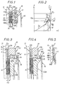
- FIGS. 1 to 4 illustrate, by way of example, application of the invention to a clutch 10 intended for intervene isolation.
- this clutch 10 comprises, in a manner known per se, a reaction plate 11, shown diagrammatically in broken lines in the figures, and, mounted mobile axially with respect to this reaction plate 11, a plate pressure 12, with, acting between these two plates 11, 12, friction linings 13A, 13B distributed annularly along two separate concentric tracks A, B.
- Track 1 is radially outermost, and track B is radially the innermost.
- the friction linings 13A, 13B are carried by a veil 14, being arranged at the outer periphery of this veil 14, and extending on either side of it for each track A, B.
- the assembly constitutes a clutch disc 15, or “friction”, which, too, is mounted axially movable by compared to the reaction plate 11.
- the plates 11, 12 are integral in rotation with a first tree, not shown, in practice a leading tree, and, more specifically, the motor output shaft in the case of the equipment of a motor vehicle, while, together, the clutch disc 15 is integral in rotation of a second shaft, also not shown, in practices a driven shaft, and, more precisely, the input shaft of the gearbox for a motor vehicle.
- the pressure plate 12 is subjected to elastic means with axial action, here a diaphragm 16, which constantly urge it towards the reaction plate 11, for tightening the gasket friction 13A, 13B, and thus the engagement of the clutch 10.
- the constituent materials of friction linings 13A, 13B are different from one of tracks A, B to another, and, on the other part, it is associated with friction linings 13A, 13B of at least one of these tracks A, B, means of progressiveness 18A, 18B.
- Each track A, B can be associated with two linings of friction (figure 1 to 4) or a friction lining (figure 5).
- FIGS. 1 to 4 there are associated means of progressiveness 18A, 18B to friction linings 13A, 13B of both tracks A, B.
- these progressive means 18A, 18B result, by way of example, from at least one side of the wall 14, the friction linings 13A, 13B are each individually carried by a blade 19A, 19B, which, coming from veil 14 itself, by appropriate cutting thereof, or attached to this web 14, is elastically deformable axially and is offset axially at rest relative to the running part of the veil 14.
- one of the tracks A, B is assigned to a permanent slip control.
- the material of the linings of friction 13A of this track A is a refractory material.
- this refractory material can be a material bronze-based sintered.
- it may for example also be a material carbon-based refractory.
- This refractory material finally, preferably has a relatively low coefficient of friction, being by example between 0.15 and 0.20.
- the friction linings 13A of track A are in practice able to generate a strong power, but fairly low thermal gradients.
- track B is devolved, according to the invention, torque transmission, both at start-up and during clutch engagement 10.
- the material of the friction linings 13B of this track B is, therefore of conventional type, and it has, in practice, a relatively high coefficient of friction, of the order for example 0.30.
- the axial thickness E A of the clutch disc 15 in line with track A is greater than its axial thickness E B in line with track B.
- Track A devolved to slip control is therefore the first to intervene at engagement.
- the progressive means 18A, 18B due to these blades 19A, 19B for tracks A, B have coefficients of different progressiveness.
- the stiffness of the blades 19A, 19B are different.
- the coefficient of progressiveness of progressive means 18A of friction linings 13A of track A the first to intervene is lower than that of progressive means 18B of friction linings 13B of the other track B.
- the axial offset d resulting from the difference between the axial thicknesses E A , E B is established in such a way that the track A of friction linings 13A the first to intervene at the engagement of the clutch 10 is that for which the means of progressiveness have the lowest coefficient of progressiveness.
- the curve I representative of the evolution of this load P as a function of this stroke C comprises, successively, as shown in solid line, two sections I A , I B
- Section I A corresponds to the intervention of only runway A.
- section slope I A of the curve I is chosen to be sufficiently low to have good sliding at this level.
- the section I B of the curve I results from the superposition on this line I ' A of a curve I' B representative of the only track B.
- the point P 1 has been represented corresponding to an operation for which, in the absence of slip, the load P transmitted is equal to the engine torque C M
- the point P 2 corresponding to an operation for which , taking into account a certain safety coefficient, this load P is greater than the torque C M
- the point P 0 corresponding to an operation for which, taking into account the desired slip, the load P is less than the engine torque C M.
- the pressure plate 12 is provided for this. fins 20 at its outer periphery.
- the pressure plate 12 is massive and in one piece.
- its face facing the clutch disc 15 present annularly, hollow, an annular groove 21 which subdivides it radially in two zones 22A, 22B each corresponding respectively to tracks A, B of this clutch disc 15.
- the diaphragm 16 relates to the part 12B, but, by a extension 16 ', it extends radially beyond the boss 23 corresponding thereof, and the means of progressiveness 18A are constituted by elastic means with axial action, here one or more Belleville 24 washers, which, bearing on the extension 16 'of the diaphragm 16, either directly, is shown 3, either by means of a rod 25, FIG. 4, relate to Part 12A.
- track A is the first to intervene.
- the thickness E A at rest of the clutch disc 15 at this track A is less than that E B of this clutch disc 15 at this track B.
- the corresponding axial offset d is axially of opposite sign to the previous one.
- the Belleville 24 washer (s) can be used to obtain a saddle curve for the curve representing the evolution of the charge P in function of stroke C, as shown in lines interrupted II in the diagram of FIG. 2, so that favor the load on the clutch part 10 corresponding to a torque transmission, outside the load around the slip control point P.
- Figure 5 illustrates, by way of example, the application of the invention to a clutch 10 intended to be incorporated into a hydraulic coupling device including the others constituents have not been represented.
- the reaction plate 11 belongs to the casing which is integral in rotation with the driving wheel of this device hydraulic coupling, while the pressure plate 12 is integral in rotation with its driven wheel, while being mobile axially in translation relative to it in the manner of a piston.
- progressive means 18B are associated only with the only track B, the corresponding friction lining 13B being carried by a blade 19B itself attached to the plate pressure 12.
- Track B which is used for slip control, and who is the first to intervene at engagement, is, here, on FIG. 5, in a reverse arrangement to the previous one, the radially innermost track.
- the track devolved to control of sliding has, here, on all the figures a height which, measured radially, is less than that of the track allocated to the transmission of torque, insofar as it does not itself ensure transmission only of a fraction of the latter.
Landscapes
- Engineering & Computer Science (AREA)
- General Engineering & Computer Science (AREA)
- Mechanical Engineering (AREA)
- Mechanical Operated Clutches (AREA)
Description
Claims (10)
- Embrayage du genre comportant un plateau de réaction (11), et, monté mobile axialement par rapport à celui-ci, un plateau de pression (12), avec, intervenant annulairement entre ces deux plateaux (11, 12), un disque d'embrayage (15) doté des garnitures de frottement (13A, 13B) réparties suivant deux pistes (A,B) concentriques distinctes, dans lequel l'une des pistes (A, B), dite première piste, d'une part, est dévolue à un contrôle de glissement, et, d'autre part, est associée à des moyens de progressivité (18A, 18B), tandis que l'autre piste (B, A), dite seconde piste, d'une part, est dévolue à la transmission de couple, tant au démarrage qu'au cours de l'engagement de l'embrayage et, d'autre part, a un matériau constitutif de la ou les garnitures de frottement (13A, 13B) différent de celui ou de ceux de la première piste en ayant un coefficient de frottement supérieur à celui de la première piste, et dans lequel au repos - charge nulle transmise par les plateaux de pression et de réaction aux pistes de frottement (A, B) - il existe un décalage axial entre les deux pistes (A, B) en sorte que la première piste est la première à intervenir à l'engagement de l'embrayage (10) et a une hauteur moindre que celle de la deuxième piste, caractérisé en ce que en combinaison, d'une part, au repos l'épaisseur axiale (EA) du disque d'embrayage (15) au droit de la première piste (A) est différente de l'épaisseur axiale (EB) du disque d'embrayage (15) au droit de la seconde piste (B) et, d'autre part, le plateau de pression (12) est en deux parties correspondantes chacune respectivement aux pistes, en ce que le matériau constitutif de la ou des garnitures de frottement de la première piste (A, B) est en matériau réfractaire présentant une grande stabilité de frottement tout en étant l'objet d'une faible usure en service, et en ce que la deuxième piste (B, A) est portée de manière rigide par l'un des plateaux de pression (12) et de réaction (11) ou est associée à des moyens de progressivité ayant un coefficient de progressivité plus élevé que ceux associés à la première piste (A).
- Embrayage suivant la revendication 1, caractérisé en ce que ledit matériau réfractaire est un matériau fritté à base de bronze.
- Embrayage suivant la revendication 1, caractérisé en ce que ledit matériau réfractaire est à base de carbone.
- Embrayage suivant l'une quelconque des revendications 1 à 3, caractérisé en ce que ledit matériau réfractaire a un coefficient de frottement compris entre 0,15 et 0,20.
- Embrayage suivant l'une quelconque des revendications 1 à 4, caractérisé en ce que le matériau constitutif de la ou des garnitures de frottement (13A, 13B) de l'autre des pistes (A, B) a un coefficient de frottement de l'ordre de 0,30.
- Embrayage suivant l'une quelconque des revendications 1 à 5, caractérisé en ce qu'il est associé des moyens de progressivité (18A,18B aux garnitures de frottement (13A, 13B) de l'une et de l'autre des pistes (A, B).
- Embrayage selon la revendication 1, caractérisé en ce que le plateau de pression (12) est massif et d'un seul tenant et en ce que la face du plateau de pression (12) tournée vers le disque d'embrayage présente annulairement en creux une gorge annulaire qui la subdivise en deux zones (22A, 22B) correspondant chacune respectivement aux pistes (A, B) de ce disque d'embrayage.
- Embrayage suivant l'une quelconque des revendications 1 à 7, caractérisé en ce que l'épaisseur au repos du disque d'embrayage (15) au droit de la première piste (A, B) est supérieure à son épaisseur au droit de la seconde piste (B, A).
- Embrayage selon l'une quelconque des revendications 1 à 6, caractérisé en ce que le plateau de pression est en deux parties (12a, 12b) correspondantes chacune respectivement aux pistes (A, B) et en ce qu'il est prévu entre ces parties des épaulements transversaux de butée (26a, 26b) pour limiter la course de l'une des parties par rapport à l'autre en direction du plateau de réaction (11).
- Embrayage selon l'une quelconque des revendications 1 à 6, caractérisé en ce que l'épaisseur au repos du disque d'embrayage (15) au droit de la première piste (A, B) est inférieure à celle de ce disque d'embrayage (15) au niveau de la deuxième piste.
Applications Claiming Priority (2)
| Application Number | Priority Date | Filing Date | Title |
|---|---|---|---|
| FR9411571 | 1994-09-28 | ||
| FR9411571A FR2724999B1 (fr) | 1994-09-28 | 1994-09-28 | Embrayage a glissement controle, notamment pour vehicule automobile |
Publications (2)
| Publication Number | Publication Date |
|---|---|
| EP0704636A1 EP0704636A1 (fr) | 1996-04-03 |
| EP0704636B1 true EP0704636B1 (fr) | 2002-03-13 |
Family
ID=9467356
Family Applications (1)
| Application Number | Title | Priority Date | Filing Date |
|---|---|---|---|
| EP19950115208 Expired - Lifetime EP0704636B1 (fr) | 1994-09-28 | 1995-09-27 | Embrayage à glissement contrôlé, notamment pour véhicule automobile |
Country Status (3)
| Country | Link |
|---|---|
| EP (1) | EP0704636B1 (fr) |
| DE (1) | DE69525803T2 (fr) |
| FR (1) | FR2724999B1 (fr) |
Families Citing this family (5)
| Publication number | Priority date | Publication date | Assignee | Title |
|---|---|---|---|---|
| DE19701292C1 (de) * | 1997-01-16 | 1998-09-17 | Mannesmann Sachs Ag | Kupplungsscheibe mit unterschiedlichen Reibwerten |
| DE602007013535D1 (de) * | 2006-01-13 | 2011-05-12 | Borgwarner Inc | Kupplungsbaugruppe und reibungsplatte |
| JP5011046B2 (ja) * | 2007-09-25 | 2012-08-29 | 株式会社キトー | 湿式摩擦板 |
| DE102016100853A1 (de) * | 2016-01-20 | 2017-07-20 | Dr. Ing. H.C. F. Porsche Aktiengesellschaft | Kupplung |
| DE102018126426A1 (de) * | 2018-10-24 | 2020-04-30 | Bayerische Motoren Werke Aktiengesellschaft | Reibkupplungsbaugruppe, Kupplung und Verfahren zur Herstellung einer Reibkupplungsbaugruppe |
Family Cites Families (9)
| Publication number | Priority date | Publication date | Assignee | Title |
|---|---|---|---|---|
| US1864252A (en) * | 1930-02-01 | 1932-06-21 | Chrysler Corp | Clutch disk |
| US2058655A (en) * | 1934-10-12 | 1936-10-27 | Borg Warner | Friction clutch |
| US2135126A (en) * | 1934-10-24 | 1938-11-01 | Russell Mfg Co | Friction clutch |
| DE2757801A1 (de) * | 1977-12-23 | 1979-06-28 | Komori Seisakusho Co | Kupplungsscheibe |
| JPS54163259A (en) * | 1978-06-14 | 1979-12-25 | Aisin Seiki | Clutch facing |
| DE3614600A1 (de) * | 1985-05-11 | 1986-11-13 | Volkswagen AG, 3180 Wolfsburg | Reibkupplung |
| JPS62233531A (ja) * | 1986-03-31 | 1987-10-13 | Sumitomo Electric Ind Ltd | 摩擦式ブレ−キ |
| JPS6376928A (ja) * | 1986-09-17 | 1988-04-07 | Toyota Motor Corp | クラツチ用摩擦材料 |
| DE4310978A1 (de) * | 1993-04-03 | 1994-10-06 | Diehl Gmbh & Co | Bauelement, bestehend aus Reibbelägen mit einer elastischen Zwischenschicht |
-
1994
- 1994-09-28 FR FR9411571A patent/FR2724999B1/fr not_active Expired - Fee Related
-
1995
- 1995-09-27 EP EP19950115208 patent/EP0704636B1/fr not_active Expired - Lifetime
- 1995-09-27 DE DE1995625803 patent/DE69525803T2/de not_active Expired - Fee Related
Also Published As
| Publication number | Publication date |
|---|---|
| DE69525803D1 (de) | 2002-04-18 |
| FR2724999A1 (fr) | 1996-03-29 |
| EP0704636A1 (fr) | 1996-04-03 |
| FR2724999B1 (fr) | 1997-01-10 |
| DE69525803T2 (de) | 2002-09-19 |
Similar Documents
| Publication | Publication Date | Title |
|---|---|---|
| EP2362111A1 (fr) | Garniture de friction annulaire pour embrayage à sec | |
| FR2600731A1 (fr) | Embrayage a volant amortisseur, notamment pour vehicule automobile. | |
| FR2669089A1 (fr) | Embrayage pour transmission a amortisseur dynamique de vibrations, notamment de vehicules automobiles. | |
| FR2616501A1 (fr) | Commande d'embrayage, notamment pour vehicule automobile, et butee de debrayage propre a la realisation d'une telle commande | |
| WO1998010202A1 (fr) | Mecanisme d'embrayage pour embrayage a friction a faible effort de debrayage | |
| FR2562969A1 (fr) | Dispositif de liaison coulissante a cannelures et application de ce dispositif a un embrayage | |
| WO2000056565A1 (fr) | Ensemble constitue d'un embrayage associe a une machine electrique, notamment pour vehicule automobile | |
| FR2817934A1 (fr) | Embrayage a disques multiples pour un vehicule automobile | |
| WO1998054477A1 (fr) | Mecanisme d'embrayage pour embrayage a friction | |
| FR2799248A1 (fr) | Installation d'embrayage multiple avec differents rayons de friction | |
| WO1999057456A1 (fr) | Double volant amortisseur de torsion, notamment pour vehicule automobile | |
| FR2724999A1 (fr) | Embrayage a glissement controle, notamment pour vehicule automobile | |
| EP0697077B1 (fr) | Appareil d'accouplement hydrocinetique, notamment pour vehicules automobiles | |
| FR2609771A1 (fr) | Ensemble de verrouillage pour appareil hydrocinetique et appareil hydrocinetique comportant un tel ensemble de verrouillage, notamment pour vehicule automobile | |
| FR2663097A1 (fr) | Volant a deux masses a monter entre un moteur a combustion et une boite de vitesses. | |
| FR2804185A1 (fr) | Embrayage a friction comportant un plateau de reaction portant un rotor d'une machine electrique tournante, notamment pour vehicule automobile | |
| EP1358412A1 (fr) | Disque de friction et procede de fabrication d'une garniture le composant | |
| WO2000006920A1 (fr) | Embrayage a friction portant le rotor d'une machine electrique, notamment pour vehicule automobile | |
| EP1709340A1 (fr) | Disque de friction d'embrayage et embrayage comportant un tel disque | |
| FR2856120A1 (fr) | Dispositif de transmission de couple, en particulier pour vehicule automobile | |
| FR2725255A1 (fr) | Embrayage a friction | |
| FR2551517A1 (fr) | Ensemble de pieces avec palier intermediaire, en particulier dispositif amortisseur de torsion tel que friction d'embrayage, notamment pour vehicule automobile | |
| EP0916034B1 (fr) | Liaison volant-couvercle d'un embrayage a friction | |
| FR2606108A1 (fr) | Ensemble elastique unitaire a pieces globalement annulaires et applications, notamment poulie de variateur de vitesse et mecanisme d'embrayage comportant un tel ensemble elastique unitaire | |
| FR2576652A1 (fr) | Dispositif amortisseur de torsion a verrouillage par galet(s), en particulier friction d'embrayage, notamment pour vehicule automobile |
Legal Events
| Date | Code | Title | Description |
|---|---|---|---|
| PUAI | Public reference made under article 153(3) epc to a published international application that has entered the european phase |
Free format text: ORIGINAL CODE: 0009012 |
|
| AK | Designated contracting states |
Kind code of ref document: A1 Designated state(s): DE GB IT |
|
| 17P | Request for examination filed |
Effective date: 19960926 |
|
| 17Q | First examination report despatched |
Effective date: 19991007 |
|
| GRAG | Despatch of communication of intention to grant |
Free format text: ORIGINAL CODE: EPIDOS AGRA |
|
| GRAG | Despatch of communication of intention to grant |
Free format text: ORIGINAL CODE: EPIDOS AGRA |
|
| GRAH | Despatch of communication of intention to grant a patent |
Free format text: ORIGINAL CODE: EPIDOS IGRA |
|
| GRAH | Despatch of communication of intention to grant a patent |
Free format text: ORIGINAL CODE: EPIDOS IGRA |
|
| REG | Reference to a national code |
Ref country code: GB Ref legal event code: IF02 |
|
| GRAA | (expected) grant |
Free format text: ORIGINAL CODE: 0009210 |
|
| AK | Designated contracting states |
Kind code of ref document: B1 Designated state(s): DE GB IT |
|
| GBT | Gb: translation of ep patent filed (gb section 77(6)(a)/1977) |
Effective date: 20020314 |
|
| REF | Corresponds to: |
Ref document number: 69525803 Country of ref document: DE Date of ref document: 20020418 |
|
| PG25 | Lapsed in a contracting state [announced via postgrant information from national office to epo] |
Ref country code: GB Free format text: LAPSE BECAUSE OF NON-PAYMENT OF DUE FEES Effective date: 20020927 |
|
| PLBE | No opposition filed within time limit |
Free format text: ORIGINAL CODE: 0009261 |
|
| STAA | Information on the status of an ep patent application or granted ep patent |
Free format text: STATUS: NO OPPOSITION FILED WITHIN TIME LIMIT |
|
| 26N | No opposition filed |
Effective date: 20021216 |
|
| GBPC | Gb: european patent ceased through non-payment of renewal fee |
Effective date: 20020927 |
|
| PGFP | Annual fee paid to national office [announced via postgrant information from national office to epo] |
Ref country code: DE Payment date: 20070910 Year of fee payment: 13 |
|
| PGFP | Annual fee paid to national office [announced via postgrant information from national office to epo] |
Ref country code: IT Payment date: 20070915 Year of fee payment: 13 |
|
| PG25 | Lapsed in a contracting state [announced via postgrant information from national office to epo] |
Ref country code: IT Free format text: LAPSE BECAUSE OF NON-PAYMENT OF DUE FEES Effective date: 20080927 Ref country code: DE Free format text: LAPSE BECAUSE OF NON-PAYMENT OF DUE FEES Effective date: 20090401 |