EP0704681A2 - Verfahren zur Durchflussmessung und zur Richtungsmessung einer Flüssigkeit in einem Rohr - Google Patents
Verfahren zur Durchflussmessung und zur Richtungsmessung einer Flüssigkeit in einem Rohr Download PDFInfo
- Publication number
- EP0704681A2 EP0704681A2 EP95306979A EP95306979A EP0704681A2 EP 0704681 A2 EP0704681 A2 EP 0704681A2 EP 95306979 A EP95306979 A EP 95306979A EP 95306979 A EP95306979 A EP 95306979A EP 0704681 A2 EP0704681 A2 EP 0704681A2
- Authority
- EP
- European Patent Office
- Prior art keywords
- angle
- pitot tube
- pressure reading
- true
- probe
- Prior art date
- Legal status (The legal status is an assumption and is not a legal conclusion. Google has not performed a legal analysis and makes no representation as to the accuracy of the status listed.)
- Withdrawn
Links
Images



Classifications
-
- G—PHYSICS
- G01—MEASURING; TESTING
- G01F—MEASURING VOLUME, VOLUME FLOW, MASS FLOW OR LIQUID LEVEL; METERING BY VOLUME
- G01F1/00—Measuring the volume flow or mass flow of fluid or fluent solid material wherein the fluid passes through a meter in a continuous flow
- G01F1/05—Measuring the volume flow or mass flow of fluid or fluent solid material wherein the fluid passes through a meter in a continuous flow by using mechanical effects
- G01F1/34—Measuring the volume flow or mass flow of fluid or fluent solid material wherein the fluid passes through a meter in a continuous flow by using mechanical effects by measuring pressure or differential pressure
- G01F1/36—Measuring the volume flow or mass flow of fluid or fluent solid material wherein the fluid passes through a meter in a continuous flow by using mechanical effects by measuring pressure or differential pressure the pressure or differential pressure being created by the use of flow constriction
- G01F1/40—Details of construction of the flow constriction devices
- G01F1/46—Pitot tubes
Definitions
- the invention relates to methods for measuring the true direction and flow rate of a fluid, particularly stack gases through a conduit which is useful for emissions monitoring.
- the United States has additional regulatory requirements which now require many electric utilities to continuously measure emissions of specified pollutants on a mass per unit time basis. Additionally, the continuous monitors must be periodically tested to assure that they are functioning properly. When such tests are done one must use a second "reference method" monitoring device. If the reference method monitor shows the continuous monitor to be reading low, the continuous monitor must be recalibrated. Adoption of these rules has put a new importance upon the errors which occur both in continuous monitoring and in the periodic reference method verification tests. Such errors can be very costly to both the supplier of the monitor and the utility. The supplier is affected because the reference method can erroneously indicate that the monitor is not meeting the performance guarantee. The utility is affected because it may have been reporting the emission of more pollutants than actually occurred.
- the new regulations establish monetary value in the form of trading credits to a measured ton of SO2 emissions. If the reference method is in error, that error will directly cause an enormous high or low use of the utility's SO2 allowance and SO2 trading credits. The value of such emissions is such that for large utilities as much as $1,000,000 per percent error in measured emissions may result.
- the technician In performing the required reference method verification tests the technician typically uses a type S (also called S-type) pitot tube made to specific dimensions. At each point the tester measures a differential pressure. The static pressure is taken at selected points. The differential pressure reading is then used to compute flow rate.
- S-type also called S-type
- the test technician frequently assumes that the direction of flow rate of a fluid in a stack is along a centerline through the stack. Consequently, he orients the pitot tube parallel to the centerline to take his readings.
- the true direction of fluid flow usually is at some angle relative to the centerline. Further, this angle will in general be different at different measurement points. To obtain more accurate flow measurements the pitot tube should be oriented along the true flow direction.
- null position a probe orientation where the differential pressure is zero. Such a direction is known as the null position. Once the null position is found the pitot tube is rotated 90° from this position to the true flow direction. Attempts to find the null position have also been imprecise. Usually the null position is assumed to be half way between two consecutive positions which provide pressure readings of opposite sign.
- the technician After the technician has oriented the pitot tube at the measurement point he takes several readings at that point. Conventionally, the technician averages the pressure readings and then takes the square root of that average as the velocity or flow rate of the gas through the measurement point.
- An S-type pitot tube is placed at the selected measurement point and oriented along an axis, typically perpendicular to the centerline of the conduit.
- a first pressure reading is taken.
- the pitot tube is rotated through a selected angle and a second pressure reading is taken.
- the readings are compared to determine if a change in sign has occurred. If not, the probe is rotated through another selected angle, usually in the same direction through the same angle, another pressure reading is taken and the two most recent pressure readings are compared. This process is repeated until a change of sign occurs.
- the probe is rotated in an opposite direction through a new, smaller angle, a pressure reading is taken and the most recent pressure readings are compared. The process is repeated until the two most recently taken pressure readings have opposite signs and the new selected angle is less than a predetermined angle, preferably one degree, or one differential pressure reading is zero. Then, an approximate null has been found.
- the S-type pitot tube is rotated in one half degree increments through a range, for example between plus 5° and minus 5° from the approximate null.
- an increment position pressure reading is taken and recorded with a corresponding probe angle.
- a statistical correlation technique using the measured angle and pressure differential is performed to find the most probable angle at which the differential pressure changes sign.
- This data preferably is fitted into a linear equation using the least squares method with the incremental position pressure readings as dependent variables and the corresponding probe angles as the independent variables. Solution of the equation determines a predicted zero crossing angle. If the predicted zero crossing angle is within a predetermined range, the predicted zero crossing angle is the true null angle. If the predicted zero crossing is outside of that range the previous steps are repeated.
- the S-type pitot tube is rotated through a selected angle to a new approximate null and readings are taken to reapply the linear equation until a true null is found.
- a direction of 90° from the true null toward the nominal flow direction is the true flow direction at the measurement point assuming pitch is negligible.
- the pitot tube is rotated 90° from the true null position to be aligned with the measured true flow direction.
- Several differential pressure readings are taken.
- the flow rate along the flow direction found by this method is calculated by taking an average of the square roots of each of the differential pressure readings. Assuming pitch is negligible, this flow rate can be converted to the flow rate in the nominal direction by multiplying the true flow rate times the cosine of the angle between the nominal flow direction and the flow direction found using this method.
- Figure 1 is a perspective view of a section of a stack in which emission readings are to be taken.
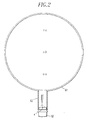
- Figure 2 is a top plan view of the stack shown in Figure 1.
- Figures 3 thru 7 are diagrams illustrating a sequence of movements of the probe made to find the null.
- Figure 8 is a diagram showing the probe having been moved from the true null position to be aligned with the true flow direction.
- the present method can best be understood in the context of a sampling probe being used in a smokestack such as is illustrated by the diagram of Figures 1 and 2.
- a probe assembly 10 is mounted to a port 62 in a stack 61 in which emissions monitoring is performed.
- the probe assembly is held on the stack 61 by a clamp 3 which attaches the probe assembly to the stack at point x.
- vector B is considered the nominal flow direction.
- the true flow direction will have three components, a vertical component, a yaw component and a pitch component.
- the vertical component is parallel to a centerline through the conduit and corresponds to positive movement along the y axis in the diagrams of Figures 3 thru 8.
- the yaw component is movement in a direction left or right relative to a person looking into the stack from the port 62. This direction is represented by the x axis in Figures 3 thru 8.
- the pitch component is movement in a direction forward or away from a person looking through the port. This direction would be represented by a z axis not shown in the drawings.
- the probe illustrated in Figures 1 and 2 is not configured to measure flow in the pitch direction unless the probe is moved 90° around the stack and advanced to the same point.
- the flow component in the yaw direction is almost always substantially greater than the pitch component the relative contribution of the pitch component to the true flow direction is very small.
- the pitch component can be usually ignored and is ignored in the present method.
- measured true flow direction we will use the phrase " measured true flow direction" to mean the actual flow direction of the fluid in the conduit as measured using the present method which does not consider pitch.
- the true flow direction may be different at different points in the same plane as indicated by the vectors A, B and C in Figure 1.
- the tip of the probe is advanced to the first selected sampling point. At each point the probe must be rotated to find the true flow direction. Then a series of differential pressure readings are taken along the true flow direction and the flow rate of the fluid in that true flow direction is calculated.
- the pitot tube Whenever the S-type pitot tube is oriented to have a zero pressure differential between its two opposite openings the pitot tube is said to be at a null position or null angle. Once the null angle is found, the true flow direction can be assumed to be 90° away provided the pitch component is negligible. The present method is used to find the null angle in the yaw direction. The measured true flow direction is then the null angle plus or minus 90°.
- Figures 3 thru 7 illustrate the movement of the pitot tube 1 in accordance with the present invention from the initial position shown in Figure 3 to the null position of Figure 7. Then the pitot tube is rotated 90° to the true flow direction shown in Figure 8.
- an x, y coordinate axis is shown as a reference.
- the y axis also corresponds to a nominal flow direction through the conduit and the vertical component of the fluid flow.
- the x-axis corresponds to the yaw direction.
- the present method is performed in two stages.
- the first stage involves taking a series of differential pressure readings using various orientations of the pitot tube.
- the second stage is the linear fit.
- This stage begins by positioning the probe at the detected zero position or half way between the position of where the two consecutive differential pressure readings were taken.
- the pitot tube is moved in half degree steps to positions along an arc from -5° to +5° around that starting position. At each position a differential pressure reading and probe angle are recorded.
- the probe angle and differential pressure readings are applied to a statistical correlation technique to determine the most probable angle at which the differential pressure changes sign.
- a linear fit technique Using the pressure as a dependent variable and probe angle as the independent variable the least squares method is used to fit a linear equation. That equation is then solved to determine a predicted zero crossing probe angle. If that angle is within the +/-5 degree range of the previous paragraph, that zero crossing is the null angle. If the predicted zero crossing angle is outside the +/-5° range, the probe is moved approximately 2 1/2° from the approximate null used to collect data from the statistical correlation towards the zero crossing angle predicted by that statistical correlation then stage 2 is repeated. Do this up to five times, or until a total of about 10 minutes. If no zero crossing is found abort the search because the method will not be useful for the particular test environment.
- the true flow direction assuming pitch is negligible is 90° from the null angle. Accordingly, the pitot tube is rotated 90° and to the measured true flow direction which corresponds to chain line 25 shown in Figure 8. At that position several differential pressure readings are taken. Then the readings are used to calculate the flow rate.
Landscapes
- Physics & Mathematics (AREA)
- Fluid Mechanics (AREA)
- General Physics & Mathematics (AREA)
- Measuring Volume Flow (AREA)
- Measuring Fluid Pressure (AREA)
- Indicating Or Recording The Presence, Absence, Or Direction Of Movement (AREA)
Applications Claiming Priority (2)
| Application Number | Priority Date | Filing Date | Title |
|---|---|---|---|
| US08/315,558 US5509313A (en) | 1994-09-30 | 1994-09-30 | Method for measuring flow rate and direction of a fluid in a conduit |
| US315558 | 1999-05-20 |
Publications (2)
| Publication Number | Publication Date |
|---|---|
| EP0704681A2 true EP0704681A2 (de) | 1996-04-03 |
| EP0704681A3 EP0704681A3 (de) | 1997-03-19 |
Family
ID=23224981
Family Applications (1)
| Application Number | Title | Priority Date | Filing Date |
|---|---|---|---|
| EP95306979A Withdrawn EP0704681A3 (de) | 1994-09-30 | 1995-10-02 | Verfahren zur Durchflussmessung und zur Richtungsmessung einer Flüssigkeit in einem Rohr |
Country Status (6)
| Country | Link |
|---|---|
| US (1) | US5509313A (de) |
| EP (1) | EP0704681A3 (de) |
| AU (1) | AU3296295A (de) |
| CA (1) | CA2159278A1 (de) |
| MX (1) | MX9504155A (de) |
| TW (1) | TW294785B (de) |
Cited By (2)
| Publication number | Priority date | Publication date | Assignee | Title |
|---|---|---|---|---|
| WO1999009376A1 (en) * | 1997-08-19 | 1999-02-25 | Valtion Teknillinen Tutkimuskeskus | Flowmeter |
| EP2447680A3 (de) * | 2010-10-28 | 2014-05-21 | Hamilton Sundstrand Corporation | Rotationsdämpfungsmechanismus für Pitot-Rohr |
Families Citing this family (5)
| Publication number | Priority date | Publication date | Assignee | Title |
|---|---|---|---|---|
| US6189390B1 (en) | 1998-04-02 | 2001-02-20 | Compliance Instrument, Inc. | Method and apparatus for measuring gas velocity or other flow characteristic |
| US6094993A (en) * | 1998-04-08 | 2000-08-01 | United Sciences Testing, Inc. | Method for measuring flow rate of a fluid in a conduit |
| DE102006025518B4 (de) * | 2006-05-30 | 2017-06-01 | Wöhler Technik GmbH | Messsonde |
| US8408082B2 (en) * | 2009-11-18 | 2013-04-02 | General Electric Company | Apparatus to measure fluids in a conduit |
| TR2023017303A1 (tr) * | 2023-12-14 | 2024-10-21 | Eski̇şehi̇r Tekni̇k Üni̇versi̇tesi̇ | Düzgün olmayan akış profillerinde debi ölçüm yöntemi. |
Family Cites Families (9)
| Publication number | Priority date | Publication date | Assignee | Title |
|---|---|---|---|---|
| US2706409A (en) * | 1950-11-24 | 1955-04-19 | Preston Joseph Henry | Flow meter |
| US3997249A (en) * | 1975-10-28 | 1976-12-14 | American Optical Corporation | Ion exchangeable segment glass |
| JPS56164960A (en) * | 1980-05-23 | 1981-12-18 | Hitachi Ltd | 1-hole pitot tube device |
| JPS60102564A (ja) * | 1983-11-08 | 1985-06-06 | Kobe Steel Ltd | ガス流速測定装置 |
| US4654813A (en) * | 1984-03-09 | 1987-03-31 | Southern Gas Association | Electronic square root error indicator |
| US5209258A (en) * | 1987-03-02 | 1993-05-11 | Daniel Flow Products | Apparatus and method for minimizing pulsation-induced errors in differential pressure flow measuring devices |
| GB2231667B (en) * | 1989-05-08 | 1992-11-18 | Rosemount Ltd | Deployable probe |
| US5394759A (en) * | 1993-04-14 | 1995-03-07 | United Sciences, Inc. | Automated flow measuring device |
| US5440217A (en) * | 1994-05-04 | 1995-08-08 | United Sciences, Inc. | Drive mechanism for automated flow measuring device |
-
1994
- 1994-09-30 US US08/315,558 patent/US5509313A/en not_active Expired - Lifetime
-
1995
- 1995-09-20 TW TW084109868A patent/TW294785B/zh not_active IP Right Cessation
- 1995-09-27 CA CA002159278A patent/CA2159278A1/en not_active Abandoned
- 1995-09-28 AU AU32962/95A patent/AU3296295A/en not_active Abandoned
- 1995-09-29 MX MX9504155A patent/MX9504155A/es not_active Application Discontinuation
- 1995-10-02 EP EP95306979A patent/EP0704681A3/de not_active Withdrawn
Cited By (3)
| Publication number | Priority date | Publication date | Assignee | Title |
|---|---|---|---|---|
| WO1999009376A1 (en) * | 1997-08-19 | 1999-02-25 | Valtion Teknillinen Tutkimuskeskus | Flowmeter |
| US6520029B1 (en) | 1997-08-19 | 2003-02-18 | Valtion Teknillinen Tutkimuskeskus | Device for measuring gas flow |
| EP2447680A3 (de) * | 2010-10-28 | 2014-05-21 | Hamilton Sundstrand Corporation | Rotationsdämpfungsmechanismus für Pitot-Rohr |
Also Published As
| Publication number | Publication date |
|---|---|
| US5509313A (en) | 1996-04-23 |
| TW294785B (de) | 1997-01-01 |
| AU3296295A (en) | 1996-04-18 |
| MX9504155A (es) | 1997-06-28 |
| CA2159278A1 (en) | 1996-03-31 |
| EP0704681A3 (de) | 1997-03-19 |
Similar Documents
| Publication | Publication Date | Title |
|---|---|---|
| Klewicki et al. | On accurately measuring statistics associated with small-scale structure in turbulent boundary layers using hot-wire probes | |
| CA2056929C (en) | Flowmeter proving apparatus | |
| US4109523A (en) | Method of determining acoustic flow meter correction factor | |
| US3924442A (en) | Pollutant variation correcting system | |
| US4942763A (en) | Flow sensor assembly | |
| US11525840B2 (en) | Non-nulling gas velocity measurement apparatus and performing non-nulling measurement of gas velocity parameters | |
| US20020157448A1 (en) | Flowmeter calibration apparatus | |
| CA2121200C (en) | Automated flow measuring device | |
| EP0704681A2 (de) | Verfahren zur Durchflussmessung und zur Richtungsmessung einer Flüssigkeit in einem Rohr | |
| US5440217A (en) | Drive mechanism for automated flow measuring device | |
| Schulze et al. | Several combination probes for surveying static and total pressure and flow direction | |
| US4584868A (en) | Apparatus for determining the supercompressibility factor of a flowing gas | |
| Kenny et al. | The application of performance standards to personal airborne dust samplers | |
| US6094993A (en) | Method for measuring flow rate of a fluid in a conduit | |
| Ingram et al. | An automated instrumentation system for flow and loss measurements in a cascade | |
| US6463808B1 (en) | Ultrasonic measurement system with chordal path | |
| US5559279A (en) | Method and apparatus for dynamic calibration of a flow monitor | |
| HatJimihail | A tool for the design and evaluation of alternative quality-control procedures | |
| Milton et al. | Calibration of DIAL and open-path systems using external gas cells | |
| JP2992404B2 (ja) | ガス漏洩源の推定方法及びその装置 | |
| SU507133A1 (ru) | Способ поверки средств измерений | |
| CLARK et al. | Calibration of hemispherical-head flow angularity probes | |
| SU853407A1 (ru) | Испытательна расходомерна установка | |
| MATSUNAGA et al. | Characteristics of a combined probe calibrated with polynomials to measure unsteady flows | |
| Adamczak et al. | APPLICATION OF THE CROSS CORRELATION FUNCTION TO THE MEASUREMENT OF ROUNDNESS PROFILES |
Legal Events
| Date | Code | Title | Description |
|---|---|---|---|
| PUAI | Public reference made under article 153(3) epc to a published international application that has entered the european phase |
Free format text: ORIGINAL CODE: 0009012 |
|
| AK | Designated contracting states |
Kind code of ref document: A2 Designated state(s): AT BE DE DK FR GB GR IT NL SE |
|
| PUAL | Search report despatched |
Free format text: ORIGINAL CODE: 0009013 |
|
| AK | Designated contracting states |
Kind code of ref document: A3 Designated state(s): AT BE DE DK FR GB GR IT NL SE |
|
| 17P | Request for examination filed |
Effective date: 19970908 |
|
| STAA | Information on the status of an ep patent application or granted ep patent |
Free format text: STATUS: THE APPLICATION HAS BEEN WITHDRAWN |
|
| 18W | Application withdrawn |
Withdrawal date: 19970922 |