EP0704733B1 - Verfahren und Einrichtung zur Herstellung einer Längswasserdichtung für Kabel - Google Patents
Verfahren und Einrichtung zur Herstellung einer Längswasserdichtung für Kabel Download PDFInfo
- Publication number
- EP0704733B1 EP0704733B1 EP95106584A EP95106584A EP0704733B1 EP 0704733 B1 EP0704733 B1 EP 0704733B1 EP 95106584 A EP95106584 A EP 95106584A EP 95106584 A EP95106584 A EP 95106584A EP 0704733 B1 EP0704733 B1 EP 0704733B1
- Authority
- EP
- European Patent Office
- Prior art keywords
- emulsion
- glass roving
- glass
- nozzle
- roving
- Prior art date
- Legal status (The legal status is an assumption and is not a legal conclusion. Google has not performed a legal analysis and makes no representation as to the accuracy of the status listed.)
- Expired - Lifetime
Links
- 238000000034 method Methods 0.000 title claims description 9
- 238000004519 manufacturing process Methods 0.000 title claims description 7
- 239000011521 glass Substances 0.000 claims abstract description 39
- 239000000839 emulsion Substances 0.000 claims abstract description 25
- 238000001035 drying Methods 0.000 claims abstract description 11
- 230000005540 biological transmission Effects 0.000 claims abstract description 9
- 239000003365 glass fiber Substances 0.000 claims abstract description 7
- 238000004804 winding Methods 0.000 claims abstract description 3
- 239000011248 coating agent Substances 0.000 claims description 11
- 238000000576 coating method Methods 0.000 claims description 11
- HRPVXLWXLXDGHG-UHFFFAOYSA-N Acrylamide Chemical compound NC(=O)C=C HRPVXLWXLXDGHG-UHFFFAOYSA-N 0.000 claims description 4
- 239000000126 substance Substances 0.000 claims description 4
- 229920001897 terpolymer Polymers 0.000 claims description 4
- 125000003178 carboxy group Chemical group [H]OC(*)=O 0.000 claims description 3
- 229930195733 hydrocarbon Natural products 0.000 claims description 3
- 150000002430 hydrocarbons Chemical class 0.000 claims description 3
- 239000000178 monomer Substances 0.000 claims description 3
- 159000000000 sodium salts Chemical class 0.000 claims description 3
- 238000009987 spinning Methods 0.000 claims 3
- 238000012512 characterization method Methods 0.000 claims 1
- 239000012188 paraffin wax Substances 0.000 claims 1
- -1 sulpho groups Chemical group 0.000 claims 1
- XLYOFNOQVPJJNP-UHFFFAOYSA-N water Substances O XLYOFNOQVPJJNP-UHFFFAOYSA-N 0.000 abstract description 15
- 238000007789 sealing Methods 0.000 abstract 2
- 239000006185 dispersion Substances 0.000 abstract 1
- 238000005470 impregnation Methods 0.000 abstract 1
- 239000000463 material Substances 0.000 abstract 1
- 239000000499 gel Substances 0.000 description 5
- 239000004033 plastic Substances 0.000 description 5
- 239000000203 mixture Substances 0.000 description 2
- 239000013307 optical fiber Substances 0.000 description 2
- 239000000565 sealant Substances 0.000 description 2
- 125000000020 sulfo group Chemical group O=S(=O)([*])O[H] 0.000 description 2
- 238000003491 array Methods 0.000 description 1
- 239000004020 conductor Substances 0.000 description 1
- 230000006866 deterioration Effects 0.000 description 1
- 239000000835 fiber Substances 0.000 description 1
- 239000002657 fibrous material Substances 0.000 description 1
- 239000000843 powder Substances 0.000 description 1
- 230000037307 sensitive skin Effects 0.000 description 1
- 230000008961 swelling Effects 0.000 description 1
- 229920001169 thermoplastic Polymers 0.000 description 1
- 239000004416 thermosoftening plastic Substances 0.000 description 1
Images

Classifications
-
- G—PHYSICS
- G02—OPTICS
- G02B—OPTICAL ELEMENTS, SYSTEMS OR APPARATUS
- G02B6/00—Light guides; Structural details of arrangements comprising light guides and other optical elements, e.g. couplings
- G02B6/44—Mechanical structures for providing tensile strength and external protection for fibres, e.g. optical transmission cables
- G02B6/4479—Manufacturing methods of optical cables
-
- G—PHYSICS
- G02—OPTICS
- G02B—OPTICAL ELEMENTS, SYSTEMS OR APPARATUS
- G02B6/00—Light guides; Structural details of arrangements comprising light guides and other optical elements, e.g. couplings
- G02B6/44—Mechanical structures for providing tensile strength and external protection for fibres, e.g. optical transmission cables
- G02B6/4401—Optical cables
- G02B6/4429—Means specially adapted for strengthening or protecting the cables
- G02B6/4434—Central member to take up tensile loads
-
- G—PHYSICS
- G02—OPTICS
- G02B—OPTICAL ELEMENTS, SYSTEMS OR APPARATUS
- G02B6/00—Light guides; Structural details of arrangements comprising light guides and other optical elements, e.g. couplings
- G02B6/44—Mechanical structures for providing tensile strength and external protection for fibres, e.g. optical transmission cables
- G02B6/4401—Optical cables
- G02B6/4429—Means specially adapted for strengthening or protecting the cables
- G02B6/44384—Means specially adapted for strengthening or protecting the cables the means comprising water blocking or hydrophobic materials
Definitions
- the invention relates to a method and a device for Production of a longitudinal water seal for cables.
- sealant In the case of cables for the transmission of electrical energy or for the transmission of information, if the cable sheath is damaged, water can penetrate and spread in the longitudinal direction of the cable. This can lead to a deterioration in the transmission properties, mechanical strength and service life.
- swellable substances such as plastic gels or swelling powder consisting of fibrous material are used as sealants when water enters.
- the sealant can be arranged between the sheathing and the cable core or, for example, in the case of cables with optical fibers according to the documents DE-OS 42 19 607 and EP A 0 261 000, between the individual conductors of the cable.
- German patent application DE 29 47 082 discloses a moisture-protected electrical energy cable, in which a shield is provided between the outer jacket and the cable core.
- the shielding consists of wires which are applied by a roping device and held by straps.
- Strands of plastic gel are arranged in the gaps between the wires, which are also applied by roping.
- the extruded outer sheath is located above the wires and the strands of plastic gel.
- the strands fill the gaps in the shielding due to the swellability of the plastic gels in such a way that moisture is prevented from being transported in the longitudinal direction of the cable.
- This type of longitudinal water seal can only be used for cables which, as described above, have shielding wires or other support members for the strands of plastic gel.
- Another disadvantage is that the low strength of the strands can lead to certain difficulties during assembly.
- the invention is based on a method and a task Device for producing a longitudinal water seal for cables propose that do not have the disadvantages mentioned above.
- the twist is Glass rovings 15 revolutions / m.
- the chemical composition of the Emulsion preferably used is characterized as follows: Terpolymer made of acrylamide, monomers containing carboxyl and sulfo groups as a W / O emulsion in paraffinic hydrocarbons, Sodium salt.
- the advantages achieved with the invention can be seen in that with a relatively simple structure and high production speed Inexpensive longitudinal water seals in Form of coated glass rovings can be produced.
- the twist facilitates the further processing of the glass roving, the after has a very good bendability when it is completed, that it can be easily wound up and stored temporarily until final assembly can be.
- the proposed emulsion causes that the glass rovings swell when exposed to moisture, so that with a contact-tight arrangement of the same in the longitudinal direction of the cable a very good one between the outer sheath and the cable core Longitudinal water tightness is achieved. With this arrangement also a strain relief can be achieved, which is especially the case with Cables with fiber optic cables is important.
- the glass roving 9 is then drawn through a nozzle 13 , a precisely defined emulsion application being determined by the diameter of the nozzle opening.
- the nozzle 13 is arranged with the nozzle opening running vertically at the upper edge of the coating bath 10 .
- a roller 12 is arranged for the deflection of the glass roving 9 such that the glass roving is pulled 9 extending through the nozzle 13 in the vertical direction.
- the glass roving 9 passes through a drying chamber 14 which has, for example, two hot air blowers which generate a temperature of approximately 220 ° C.
- the dwell time of the glass roving 9 in the drying chamber 14 also depends on the take-off speed.
- the take-off speed is generated by a take-off device 15 arranged behind the drying chamber 14 in the direction of production (arrow P) , for example by a continuously variable DC motor.
- the glass roving 9 is wound in a cross winding on a cylindrical spool 18 which is driven as not described further.
- thermoplastic synthetic yarn it is also possible to tie two or more coated glass rovings 9 together with thermoplastic synthetic yarn to form a cord, which can also be used as a longitudinal water seal.
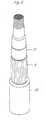
- longitudinal water seals in the form of glass rovings 9 are arranged between the outer jacket 20 and the cable core 21 (not described in more detail) of a cable used, for example, for energy transmission.
- the glass rovings 9 extend in the longitudinal direction of the cable and are strung together in a touch-tight manner. If the outer jacket 20 is damaged and water or moisture penetrates, the emulsion application which reacts to the moisture causes the glass rovings 9 to swell, so that the spreading of the water or moisture in the longitudinal direction of the cable is prevented.
Landscapes
- Physics & Mathematics (AREA)
- General Physics & Mathematics (AREA)
- Optics & Photonics (AREA)
- Engineering & Computer Science (AREA)
- Manufacturing & Machinery (AREA)
- Installation Of Indoor Wiring (AREA)
- Insulated Conductors (AREA)
- Laying Of Electric Cables Or Lines Outside (AREA)
- Ropes Or Cables (AREA)
- Surface Treatment Of Glass Fibres Or Filaments (AREA)
Description
- Fig. 1
- eine schematische Darstellung der Einrichtung zur Herstellung von Längswasserdichtungen für Kabel und
- Fig.2
- eine perspektivische Darstellung eines Energieübertragungskabels mit den erfindungsgemässen Längswasserdichtungen.
- Terpolymer aus Acrylamid, carboxyl- und sulfogruppenhaltigen Monomeren als W/O-Emulsion in paraffinischen Kohlenwasserstoffen, Natriumsalz.
Claims (9)
- Verfahren zur Herstellung einer Längswasserdichtung für Kabel, dadurch gekennzeichnet,dass von einer Vorratsspule (1) ablaufende Glasfaseranordnungen (2) zu einem Glasroving (9) verdrillt werden,dass der Glasroving (9) in eine Emulsion (11) getaucht wird, die bewirkt, daß die Glasroving bei Feuchtigkeitszutritt aufquellen,dass der Glasroving (9) anschliessend durch eine Düse (13) gezogen wird, wobei ein genau definierter Emulsionsauftrag erzeugt wird,dass der mit der Emulsion (11) benetzte Glasroving (9) getrocknet wird, unddass der getrocknete Glasroving (9) auf einer Spule (18) aufgewickelt wird.
- Verfahren nach Anspruch 1,
dadurch gekennzeichnet,dass die Verdrillung des Glasrovings (9) 15 Umdrehungen/m beträgt. - Verfahren nach Anspruch 1,
dadurch gekennzeichnet,dass eine Emulsion (11) folgender chemischer Charakterisierung verwendet wird: Terpolymer aus Acrylamid, carboxyl- und sulfogruppenhaltigen Monomeren als W/O-Emulsion in paraffinischen Kohlenwasserstoffen, Natriumsalz. - Verfahren nach Anspruch 1,
dadurch gekennzeichnet,dass der genau definierte Emulsionsauftrag durch den Durchmesser der Düsenöffnung der Düse (13) bestimmt wird. - Verfahren nach Anspruch 1,
dadurch gekennzeichnet,dass mindestens zwei Glasrovings (9) zu einer Kordel bzw. zu einer Längswasserdichtung zusammengebunden werden. - Einrichtung zur Durchführung des Verfahrens nach Anspruch 1,
dadurch gekennzeichnet,dass ein Dralltopf (3) vorgesehen ist, in welchem eine Vorratsspule (1) befestigt ist,dass der Dralltopf (3) mittels eines Motors (4) und eines Getriebes (5) angetrieben ist,dass ein mit einer Emulsion (11) gefülltes Beschichtungsbad (10) vorgesehen ist,dass in Fertigungsrichtung nach dem Beschichtungsbad (10) eine Düse (13) vorgesehen ist, durch die das berchichtete Glas roving gezogen wrid,dass eine Trockenkammer (14) mit mindestens einem Heissluftgebläse vorgesehen ist,dass eine in Fertigungsrichtung hinter der Trockenkammer (14) angeordnete Abzugsvorrichtung (15) vorgesehen ist, mittels welcher der Glasroving (9) von der Vorratsspule (1) durch das Beschichtungsbad (10) und die Trockenkammer (14) ziehbar ist, unddass eine angetriebene Spule (18) für die Aufwicklung des Glasrovings (9) vorgesehen ist. - Einrichtung nach Anspruch 6,
dadurch gekennzeichnet,dass über dem Dralltopf (3) eine in einem Träger (6) befindliche Führungsöffnung (7) und eine am Träger (6) angeordnete Umlenkung (8) vorgesehen sind, durch welche die Glasfaseranordnung (2) geführt bzw. umgelenkt werden. - Einrichtung nach Anspruch 6,
dadurch gekennzeichnet,dass die Düse (13) bei senkrecht verlaufender Düsenöffnung am oberen Rand des Beschichtungsbades (10) angeordnet ist und dass am Boden des Beschichtungsbades (10) eine Rolle (12) für die Umlenkung des Glasrovings (9) derart angeordnet ist, dass der Glasroving (9) in senkrechter Richtung verlaufend durch die Düse (13) gezogen wird. - Einrichtung nach einem der Ansprüche 6 bis 8,
dadurch gekennzeichnet,dass das Getriebe (5) stufenlos regulierbar ist.
Applications Claiming Priority (2)
| Application Number | Priority Date | Filing Date | Title |
|---|---|---|---|
| CH2894/94 | 1994-09-23 | ||
| CH289494 | 1994-09-23 |
Publications (2)
| Publication Number | Publication Date |
|---|---|
| EP0704733A1 EP0704733A1 (de) | 1996-04-03 |
| EP0704733B1 true EP0704733B1 (de) | 1998-09-30 |
Family
ID=4243992
Family Applications (1)
| Application Number | Title | Priority Date | Filing Date |
|---|---|---|---|
| EP95106584A Expired - Lifetime EP0704733B1 (de) | 1994-09-23 | 1995-05-02 | Verfahren und Einrichtung zur Herstellung einer Längswasserdichtung für Kabel |
Country Status (4)
| Country | Link |
|---|---|
| EP (1) | EP0704733B1 (de) |
| AT (1) | ATE171786T1 (de) |
| DE (1) | DE59503773D1 (de) |
| DK (1) | DK0704733T3 (de) |
Families Citing this family (1)
| Publication number | Priority date | Publication date | Assignee | Title |
|---|---|---|---|---|
| US5689601A (en) * | 1995-08-24 | 1997-11-18 | Owens-Corning Fiberglas Technology Inc. | Water blocking optical cable reinforcement |
Family Cites Families (6)
| Publication number | Priority date | Publication date | Assignee | Title |
|---|---|---|---|---|
| FR2597856B1 (fr) * | 1986-04-24 | 1992-01-10 | Saint Gobain Vetrotex | Procede de traitement de fibres de verre continues et produits en resultant |
| US4913517A (en) * | 1988-07-11 | 1990-04-03 | American Telephone And Telegraph Company, At&T Bell Laboratories | Communication cable having water blocking strength members |
| US5000539A (en) * | 1989-07-31 | 1991-03-19 | Cooper Industries, Inc. | Water blocked cable |
| FR2694442B1 (fr) * | 1992-07-28 | 1994-09-02 | Lens Cableries | Filin d'étanchéité, pour câbles d'énergie et de télécommunication. |
| EP0666243A1 (de) * | 1994-02-08 | 1995-08-09 | Roblon A/S | Glasfaserbündel sowie Verfahren und Vorrichtung zu dessen Herstellung |
| GB9411028D0 (en) * | 1994-06-02 | 1994-07-20 | Cookson Group Plc | Water blocking composites and their use in cable manufacture |
-
1995
- 1995-05-02 EP EP95106584A patent/EP0704733B1/de not_active Expired - Lifetime
- 1995-05-02 DK DK95106584T patent/DK0704733T3/da active
- 1995-05-02 DE DE59503773T patent/DE59503773D1/de not_active Expired - Fee Related
- 1995-05-02 AT AT95106584T patent/ATE171786T1/de not_active IP Right Cessation
Also Published As
| Publication number | Publication date |
|---|---|
| DK0704733T3 (da) | 1999-06-21 |
| ATE171786T1 (de) | 1998-10-15 |
| EP0704733A1 (de) | 1996-04-03 |
| DE59503773D1 (de) | 1998-11-05 |
Similar Documents
| Publication | Publication Date | Title |
|---|---|---|
| DE60030375T2 (de) | Kommunikationslichtleitfaserkabel | |
| DE69617965T2 (de) | Wasserblockierendes, verstärktes optisches kabel | |
| US4269024A (en) | Strength members for the reinforcement of optical fibre cables | |
| DE69002285T2 (de) | Faseroptisches kabel. | |
| DE2818574C2 (de) | Verfahren zur kontinuierlichen Herstellung von Kabel-Elementen mit optischen Fasern und Vorrichtung zur Durchführung des Verfahrens | |
| DE3788245T2 (de) | Optisches Kabel. | |
| DE3002523C2 (de) | Verfahren zur Herstellung einer Verseileinheit und Einrichtung zur durchführung des Verfahrens | |
| DE29608971U1 (de) | Seil für die Mitnahme und Weitergabe von Papierbahnen bei der Herstellung von Papier und Kartonagen auf Papiermaschinen | |
| DE4101082C1 (de) | ||
| DE3109469C2 (de) | ||
| DE3407520C2 (de) | Verfahren und Vorrichtung zur farblichen Kennzeichnung von Lichtwellenleitern | |
| DE3232108A1 (de) | Optisches kabel | |
| DE2735476A1 (de) | Verfahren und vorrichtung zur herstellung von kabeln und leitungen mit sz-verseilten verseilelementen | |
| DE3023669C2 (de) | Selbsttragendes optisches Nachrichtenkabel | |
| EP0704733B1 (de) | Verfahren und Einrichtung zur Herstellung einer Längswasserdichtung für Kabel | |
| DE3112422C2 (de) | ||
| DE2757786A1 (de) | Verfahren zur kontinuierlichen herstellung eines optischen uebertragungselementes | |
| DE3688229T2 (de) | Verfahren fuer herstellung eines faseroptischen kabels. | |
| WO2016150632A1 (de) | Verfahren und vorrichtung zur herstellung eines rohrverbundes aus kabelrohren | |
| DE2259703C3 (de) | Selbsttragendes Luftkabel | |
| DE3026999C2 (de) | SZ-verseiltes, mehradriges elektrisches Energiekabel | |
| DE2433099A1 (de) | Elektrisches kabel mit zugaufnehmenden elementen aus hochfesten kunststoffaeden | |
| DE19910653A1 (de) | Metallfreies optisches Kabel | |
| DE3239024C2 (de) | ||
| DE2403047A1 (de) | Elektrische leitung aus mehreren zu einem buendel mit reversierendem schlag verseilten adern und verfahren zur herstellung |
Legal Events
| Date | Code | Title | Description |
|---|---|---|---|
| PUAI | Public reference made under article 153(3) epc to a published international application that has entered the european phase |
Free format text: ORIGINAL CODE: 0009012 |
|
| AK | Designated contracting states |
Kind code of ref document: A1 Designated state(s): AT BE CH DE DK FR GB IT LI NL SE |
|
| 17P | Request for examination filed |
Effective date: 19960729 |
|
| GRAG | Despatch of communication of intention to grant |
Free format text: ORIGINAL CODE: EPIDOS AGRA |
|
| 17Q | First examination report despatched |
Effective date: 19971210 |
|
| GRAG | Despatch of communication of intention to grant |
Free format text: ORIGINAL CODE: EPIDOS AGRA |
|
| GRAG | Despatch of communication of intention to grant |
Free format text: ORIGINAL CODE: EPIDOS AGRA |
|
| GRAH | Despatch of communication of intention to grant a patent |
Free format text: ORIGINAL CODE: EPIDOS IGRA |
|
| GRAH | Despatch of communication of intention to grant a patent |
Free format text: ORIGINAL CODE: EPIDOS IGRA |
|
| GRAA | (expected) grant |
Free format text: ORIGINAL CODE: 0009210 |
|
| AK | Designated contracting states |
Kind code of ref document: B1 Designated state(s): AT BE CH DE DK FR GB IT LI NL SE |
|
| PG25 | Lapsed in a contracting state [announced via postgrant information from national office to epo] |
Ref country code: IT Free format text: LAPSE BECAUSE OF FAILURE TO SUBMIT A TRANSLATION OF THE DESCRIPTION OR TO PAY THE FEE WITHIN THE PRESCRIBED TIME-LIMIT;WARNING: LAPSES OF ITALIAN PATENTS WITH EFFECTIVE DATE BEFORE 2007 MAY HAVE OCCURRED AT ANY TIME BEFORE 2007. THE CORRECT EFFECTIVE DATE MAY BE DIFFERENT FROM THE ONE RECORDED. Effective date: 19980930 Ref country code: GB Free format text: LAPSE BECAUSE OF FAILURE TO SUBMIT A TRANSLATION OF THE DESCRIPTION OR TO PAY THE FEE WITHIN THE PRESCRIBED TIME-LIMIT Effective date: 19980930 Ref country code: FR Free format text: LAPSE BECAUSE OF FAILURE TO SUBMIT A TRANSLATION OF THE DESCRIPTION OR TO PAY THE FEE WITHIN THE PRESCRIBED TIME-LIMIT Effective date: 19980930 |
|
| REF | Corresponds to: |
Ref document number: 171786 Country of ref document: AT Date of ref document: 19981015 Kind code of ref document: T |
|
| REG | Reference to a national code |
Ref country code: CH Ref legal event code: EP |
|
| REG | Reference to a national code |
Ref country code: CH Ref legal event code: NV Representative=s name: OK PAT AG |
|
| REF | Corresponds to: |
Ref document number: 59503773 Country of ref document: DE Date of ref document: 19981105 |
|
| PG25 | Lapsed in a contracting state [announced via postgrant information from national office to epo] |
Ref country code: SE Free format text: LAPSE BECAUSE OF FAILURE TO SUBMIT A TRANSLATION OF THE DESCRIPTION OR TO PAY THE FEE WITHIN THE PRESCRIBED TIME-LIMIT Effective date: 19981231 |
|
| EN | Fr: translation not filed | ||
| GBV | Gb: ep patent (uk) treated as always having been void in accordance with gb section 77(7)/1977 [no translation filed] |
Effective date: 19980930 |
|
| PG25 | Lapsed in a contracting state [announced via postgrant information from national office to epo] |
Ref country code: BE Free format text: LAPSE BECAUSE OF NON-PAYMENT OF DUE FEES Effective date: 19990531 |
|
| REG | Reference to a national code |
Ref country code: DK Ref legal event code: T3 |
|
| PLBE | No opposition filed within time limit |
Free format text: ORIGINAL CODE: 0009261 |
|
| STAA | Information on the status of an ep patent application or granted ep patent |
Free format text: STATUS: NO OPPOSITION FILED WITHIN TIME LIMIT |
|
| 26N | No opposition filed | ||
| BERE | Be: lapsed |
Owner name: BANDFABRIK STREIFF A.G. Effective date: 19990531 |
|
| PGFP | Annual fee paid to national office [announced via postgrant information from national office to epo] |
Ref country code: AT Payment date: 20010319 Year of fee payment: 7 |
|
| PGFP | Annual fee paid to national office [announced via postgrant information from national office to epo] |
Ref country code: CH Payment date: 20020402 Year of fee payment: 8 |
|
| PG25 | Lapsed in a contracting state [announced via postgrant information from national office to epo] |
Ref country code: AT Free format text: LAPSE BECAUSE OF NON-PAYMENT OF DUE FEES Effective date: 20020502 |
|
| PGFP | Annual fee paid to national office [announced via postgrant information from national office to epo] |
Ref country code: DE Payment date: 20020515 Year of fee payment: 8 |
|
| PGFP | Annual fee paid to national office [announced via postgrant information from national office to epo] |
Ref country code: DK Payment date: 20020527 Year of fee payment: 8 |
|
| PGFP | Annual fee paid to national office [announced via postgrant information from national office to epo] |
Ref country code: NL Payment date: 20020531 Year of fee payment: 8 |
|
| PG25 | Lapsed in a contracting state [announced via postgrant information from national office to epo] |
Ref country code: LI Free format text: LAPSE BECAUSE OF NON-PAYMENT OF DUE FEES Effective date: 20030531 Ref country code: CH Free format text: LAPSE BECAUSE OF NON-PAYMENT OF DUE FEES Effective date: 20030531 |
|
| PG25 | Lapsed in a contracting state [announced via postgrant information from national office to epo] |
Ref country code: NL Free format text: LAPSE BECAUSE OF NON-PAYMENT OF DUE FEES Effective date: 20031201 Ref country code: DK Free format text: LAPSE BECAUSE OF NON-PAYMENT OF DUE FEES Effective date: 20031201 |
|
| PG25 | Lapsed in a contracting state [announced via postgrant information from national office to epo] |
Ref country code: DE Free format text: LAPSE BECAUSE OF NON-PAYMENT OF DUE FEES Effective date: 20031202 |
|
| REG | Reference to a national code |
Ref country code: DK Ref legal event code: EBP |
|
| REG | Reference to a national code |
Ref country code: CH Ref legal event code: PL |
|
| NLV4 | Nl: lapsed or anulled due to non-payment of the annual fee |
Effective date: 20031201 |