EP0704748A1 - Dispositif d'enroulement de matériaux enroulés - Google Patents
Dispositif d'enroulement de matériaux enroulés Download PDFInfo
- Publication number
- EP0704748A1 EP0704748A1 EP95113031A EP95113031A EP0704748A1 EP 0704748 A1 EP0704748 A1 EP 0704748A1 EP 95113031 A EP95113031 A EP 95113031A EP 95113031 A EP95113031 A EP 95113031A EP 0704748 A1 EP0704748 A1 EP 0704748A1
- Authority
- EP
- European Patent Office
- Prior art keywords
- roll material
- winding
- winding drum
- sensor
- drive
- Prior art date
- Legal status (The legal status is an assumption and is not a legal conclusion. Google has not performed a legal analysis and makes no representation as to the accuracy of the status listed.)
- Granted
Links
- 238000004804 winding Methods 0.000 title claims abstract description 78
- 230000004888 barrier function Effects 0.000 claims description 5
- 238000000034 method Methods 0.000 claims description 5
- 210000001015 abdomen Anatomy 0.000 description 7
- 230000015572 biosynthetic process Effects 0.000 description 2
- 230000001105 regulatory effect Effects 0.000 description 2
- 230000005540 biological transmission Effects 0.000 description 1
- 230000007423 decrease Effects 0.000 description 1
- 238000010586 diagram Methods 0.000 description 1
- 238000003780 insertion Methods 0.000 description 1
- 230000037431 insertion Effects 0.000 description 1
Images

Classifications
-
- G—PHYSICS
- G03—PHOTOGRAPHY; CINEMATOGRAPHY; ANALOGOUS TECHNIQUES USING WAVES OTHER THAN OPTICAL WAVES; ELECTROGRAPHY; HOLOGRAPHY
- G03B—APPARATUS OR ARRANGEMENTS FOR TAKING PHOTOGRAPHS OR FOR PROJECTING OR VIEWING THEM; APPARATUS OR ARRANGEMENTS EMPLOYING ANALOGOUS TECHNIQUES USING WAVES OTHER THAN OPTICAL WAVES; ACCESSORIES THEREFOR
- G03B27/00—Photographic printing apparatus
- G03B27/32—Projection printing apparatus, e.g. enlarger, copying camera
- G03B27/52—Details
- G03B27/58—Baseboards, masking frames, or other holders for the sensitive material
- G03B27/587—Handling photosensitive webs
- G03B27/588—Supply rolls; Cutting arrangements
Definitions
- the present invention relates to a winding device for roll material, in particular for an image exposure device with a driven winding drum.
- Such a device is known from EP-0 463 997.
- two pivotable guide elements are provided which guide the roll material or strip material around a hollow cylindrical guide sleeve which can be pushed onto a rotatably mounted, drivable winding core.
- the guide sleeve can be snapped into its operating position.
- the winding drum can be controlled in such a way that the roll material always occupies a certain position in front of the winding drum, which can be done by accelerating or braking the drive of the winding drum. This ensures that the roll material has a constant low tension between the position of the sensor and the winding core, thereby avoiding unevenness during winding.
- bulging of the roll material can be detectable by the sensor.
- the roll material can be wound up particularly evenly if it forms a "belly" in front of the winding drum.
- the formation of the belly can be detected by the sensor, which in turn controls the drive of the winding drum accordingly, so that such a belly is always formed.
- the roll material can be guided to the winding drum in a substantially vertical direction. It has also been found here that this measure improves the uniform winding on the winding core of the winding drum.
- the roll material can be guided at an angle of 80 ° -100 ° to the horizontal. At the beginning of the winding process, an angle of approximately 100 ° with the horizontal is formed, which with increasing The winding diameter decreases so that an angle of approximately 80 ° to the horizontal is reached when the winding is completely wound up.
- the senor of the winding device can have a rocker arm which can be provided with a spring.
- a rocker arm can scan at one end the belly of the roll material to be formed, the other end can interact with the sensor.
- the roll material can be scanned without being influenced.
- the senor which can have a fork light barrier, for example, can emit an analog output signal.
- the output signal of the sensor contains information about the size of the distance of the roll material from the sensor.
- the drive of the winding drum can be regulated particularly sensitively.
- a deflection device for example in the form of a free-running roller, for the roll material can be arranged above the winding drum. This measure ensures that the belly can form between a defined distance, namely between the deflection direction and the winding core. This also contributes to an even winding.
- the senor can be arranged on a movable guide element for the roll material.
- a movable guide element moves away from the winding axis of the winding drum with increasing winding diameter.
- the sensor is arranged on this guide element, there is the great advantage that an increasing winding diameter does not influence the formation of the belly of the roll material, since the sensor has a constant distance from the outer circumference of the winding due to its arrangement.
- the roll material can be passed through a braking device before winding.
- a braking device has an eddy current brake, there is the very significant advantage of a completely even and jerk-free movement of the roll material, since no discontinuities or irregularities enter the system through the use of the eddy current brake, since the eddy current brake, in contrast to, for example, a direct current motor or the like, generates a constant braking torque.
- An advantageous control of the device according to the invention can be achieved in that the drive of the winding drum is controlled in such a way that the roll material forms a bulge with a substantially constant curvature.
- the image exposure device shown in FIG. 1 basically consists of a schematically indicated feeding device 10, a braking device 20, an exposure and deflection roller 30, a drive 40 and the winding unit 50.
- a cutting device, not shown, is provided between the braking device 20 and the roller 30.
- the schematically illustrated feed device 10 comprises a pair of rollers and various guide and guide plates, which enable a controlled feed of the roll material, for example a paper web made of photo paper.
- the braking device 20 has a brake roller 22 and a counter-pressure roller 24, between which the paper web 12 is guided.
- the brake roller 22 is connected via a belt transmission to an eddy current brake, not shown.
- the braking force can be controlled via the strength of the eddy current.
- the exposure and deflection roller 30 serves, on the one hand, to create a uniform support for the paper web so that an incoming exposure beam S can expose the paper web without causing irregularities.
- the paper web is deflected downwards from the horizontal at an angle of approximately 40 ° by the roller 30.
- the paper web is then passed through the drive device 40, which has a driven roller 42 and a counter-pressure device 44.
- the counter pressure device 44 consists of several individually sprung rollers, whereby a distortion and displacement-free drive of the paper web is achieved.
- the paper web 12 After passing through the drive device 40, the paper web 12 reaches the winding device 50, which is arranged in a housing 52.
- the winding device 50 has a driven winding drum 54, the drive of the winding drum not being shown. Furthermore, two articulated guide plates 56 and 58 are arranged in the housing 52, which ensure a uniform winding.
- the guide plate 56 has at its front end a roller 57 that rolls on the winding that is being formed.
- the guide plate 58 is provided with two rollers 59 and 60, which ensure automatic winding onto the winding drum 54.
- the winding device 50 has a deflection roller 62 which deflects the paper web 12 in a substantially vertical direction.
- a sensor 64 is attached to the guide plate 56 approximately in the middle between the deflection roller 62 and the outer circumference of the winding drum 54.
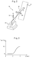
- Fig. 2 shows schematically the design of the sensor 64, which has a fork light barrier 66 and a rocker arm 68.
- the rocker arm 68 is mounted on a joint 69 and spring-loaded with a spring 70.
- the right end of the rocker arm 68 in FIG. 2 scans the position of the paper web 12, the in FIG. 2 the left end of the rocker arm 68 cooperates with the fork light barrier 66.
- the characteristic curve of the sensor 64 from FIG. 2 is shown in FIG. 3.
- the photo stream of the fork light barrier 66 contains information about the size of the distance of the paper web 12 from the sensor 64. In this way, the size of the photo stream generated enables the distance of the paper web 12 to be easily determined in a range of approximately 2 mm . Since the rocker arm 68 is angled, the travel resolution can be set by the choice of the lever ratio.
- the paper web 12 is fed from the feed device 10 and arrives in the braking device 20. Subsequently, the paper web 12 is guided into the take-up device 50 via the exposure roller 30 and the drive device 40.
- the guide plates 56 and 58 provided there and the rollers 57, 59 and 60 connected therewith the start of the paper web is automatically wound onto the winding drum when the drive device 40 and the drive of the winding drum 54 are actuated.
- the drive device 40 is put into operation and pulls the paper web 12 over the exposure roller 30, the braking device 20 in conjunction with the provided eddy current brake ensuring that the paper web rolls off smoothly and smoothly.
- the exposure beam S is directed onto the paper web 12 and deflected perpendicular to the paper web.
- the drive of the deflection mirror for the exposure beam S is connected to the stepper motor of the drive device 40 in order to achieve synchronization between the longitudinal movement of the paper web and the transverse movement of the exposure beam S. This compensates for tolerances in the drive of the deflection mirror and prevents any image distortions that may occur.
- the sensor 64 detects the position of the paper web 12 in front of the winding drum 54.
- the drive of the winding drum 54 is controlled in such a way that the paper web 12 forms a constant bulge A with a substantially constant curvature, which ensures an absolutely uniform winding.
- the drive of the winding drum 54 is regulated by the output signal of the sensor 64, which contains information about the distance of the abdomen A from the sensor 64. In this way, a very sensitive and even control is achieved.
- the drive device 40 is arranged close to the exposure roller 30 and the winding device 50 is arranged close to the drive device 40, the paper losses which arise when changing the paper selection are extremely small.
Landscapes
- Physics & Mathematics (AREA)
- General Physics & Mathematics (AREA)
- Controlling Rewinding, Feeding, Winding, Or Abnormalities Of Webs (AREA)
- Registering, Tensioning, Guiding Webs, And Rollers Therefor (AREA)
- Replacement Of Web Rolls (AREA)
- Storage Of Web-Like Or Filamentary Materials (AREA)
- Processing And Handling Of Plastics And Other Materials For Molding In General (AREA)
- Rolls And Other Rotary Bodies (AREA)
- Projection-Type Copiers In General (AREA)
- Exposure And Positioning Against Photoresist Photosensitive Materials (AREA)
- Winding Of Webs (AREA)
Applications Claiming Priority (2)
| Application Number | Priority Date | Filing Date | Title |
|---|---|---|---|
| IT94BZ000057A IT1278338B1 (it) | 1994-09-19 | 1994-09-19 | Dispositivo di riavvolgimento per materiale bobinato. |
| ITBZ940057 | 1994-09-19 |
Publications (2)
| Publication Number | Publication Date |
|---|---|
| EP0704748A1 true EP0704748A1 (fr) | 1996-04-03 |
| EP0704748B1 EP0704748B1 (fr) | 2001-10-31 |
Family
ID=11346667
Family Applications (1)
| Application Number | Title | Priority Date | Filing Date |
|---|---|---|---|
| EP95113031A Expired - Lifetime EP0704748B1 (fr) | 1994-09-19 | 1995-08-18 | Dispositif d'enroulement de matériaux enroulés |
Country Status (9)
| Country | Link |
|---|---|
| US (1) | US5634608A (fr) |
| EP (1) | EP0704748B1 (fr) |
| JP (1) | JPH08169605A (fr) |
| AT (1) | ATE208056T1 (fr) |
| AU (1) | AU688079B2 (fr) |
| CA (1) | CA2157630A1 (fr) |
| DE (1) | DE59509778D1 (fr) |
| ES (1) | ES2162884T3 (fr) |
| IT (1) | IT1278338B1 (fr) |
Cited By (1)
| Publication number | Priority date | Publication date | Assignee | Title |
|---|---|---|---|---|
| DE19926490C2 (de) * | 1998-06-12 | 2003-04-30 | Fuji Photo Film Co Ltd | Vorrichtung zum Transportieren von photoempfindlichem Material |
Citations (9)
| Publication number | Priority date | Publication date | Assignee | Title |
|---|---|---|---|---|
| FR707730A (fr) * | 1930-03-19 | 1931-07-11 | Dispositif avertisseur de mauvais enroulement des films cinématographiques | |
| US3547369A (en) * | 1968-09-12 | 1970-12-15 | Bell & Howell Co | Film tension control device |
| DE2445259A1 (de) * | 1972-05-31 | 1976-04-08 | Agfa Gevaert Ag | Vorrichtung zum schrittweisen transport eines bandfoermigen materials |
| DE3116041A1 (de) * | 1981-04-22 | 1982-11-11 | Agfa-Gevaert Ag, 5090 Leverkusen | Vorrichtung zum aufwickeln von bandfoermigem material in einem fotografischen behandlungsgeraet |
| WO1990005690A1 (fr) * | 1988-11-21 | 1990-05-31 | Heino Hautio | Frein pour rouleau |
| EP0463997A1 (fr) | 1990-06-29 | 1992-01-02 | Gretag Imaging Ag | Cassette pour l'enroulement de matériau photographique en bande |
| EP0476418A1 (fr) * | 1990-09-04 | 1992-03-25 | Minnesota Mining And Manufacturing Company | Dispositif pour alimenter du matériel imprimable dans une installation d'impression |
| US5117241A (en) * | 1990-04-04 | 1992-05-26 | Eastman Kodak Company | Thermal printing apparatus with tensionless donor web during printing |
| US5176334A (en) * | 1990-06-15 | 1993-01-05 | Stahlkontor Maschinenabau Gmbh | Apparatus for maintaining a tension in an elongated continuously advanced flexible element |
Family Cites Families (11)
| Publication number | Priority date | Publication date | Assignee | Title |
|---|---|---|---|---|
| DE1774704C3 (de) * | 1968-08-17 | 1980-10-02 | Metalloxyd Gmbh, 5000 Koeln | Vorrichtung zum Wickeln von Metallbundspulen |
| US3715087A (en) * | 1971-02-18 | 1973-02-06 | Prod Inc | Sheet film storage magazine |
| US4025005A (en) * | 1974-09-21 | 1977-05-24 | Agfa-Gevaert, A.G. | Web feeding and collecting apparatus for photographic printers or the like |
| JPS57205731A (en) * | 1981-06-12 | 1982-12-16 | Konishiroku Photo Ind Co Ltd | Winder for photographic paper |
| GB2103188A (en) * | 1981-08-06 | 1983-02-16 | Rank Organisation Ltd | Winding film into large firm rolls under controlled tension |
| DE3151956A1 (de) * | 1981-12-30 | 1983-07-07 | Agfa-Gevaert Ag, 5090 Leverkusen | Einrichtung zum transportieren eines bandfoermigen kopiermaterials |
| DE3151932A1 (de) * | 1981-12-30 | 1983-07-07 | Agfa-Gevaert Ag, 5090 Leverkusen | Einrichtung zum transportieren eines bandfoermigen kopiermaterials |
| US4447016A (en) * | 1982-06-01 | 1984-05-08 | Perfecto, Inc. | Rewind apparatus for metal strips |
| JPH0179041U (fr) * | 1987-11-17 | 1989-05-26 | ||
| US4996541A (en) * | 1989-04-19 | 1991-02-26 | Minolta Camera Kabushiki Kaisha | Film conveying apparatus |
| US5053795A (en) * | 1990-11-05 | 1991-10-01 | Minnesota Mining And Manufacturing Company | Reusable cartridge for storing and dispensing light sensitive web material |
-
1994
- 1994-09-19 IT IT94BZ000057A patent/IT1278338B1/it active IP Right Grant
-
1995
- 1995-08-18 EP EP95113031A patent/EP0704748B1/fr not_active Expired - Lifetime
- 1995-08-18 AT AT95113031T patent/ATE208056T1/de not_active IP Right Cessation
- 1995-08-18 DE DE59509778T patent/DE59509778D1/de not_active Expired - Fee Related
- 1995-08-18 ES ES95113031T patent/ES2162884T3/es not_active Expired - Lifetime
- 1995-08-24 AU AU30258/95A patent/AU688079B2/en not_active Ceased
- 1995-09-06 CA CA002157630A patent/CA2157630A1/fr not_active Abandoned
- 1995-09-15 US US08/528,931 patent/US5634608A/en not_active Expired - Fee Related
- 1995-09-19 JP JP7239749A patent/JPH08169605A/ja active Pending
Patent Citations (9)
| Publication number | Priority date | Publication date | Assignee | Title |
|---|---|---|---|---|
| FR707730A (fr) * | 1930-03-19 | 1931-07-11 | Dispositif avertisseur de mauvais enroulement des films cinématographiques | |
| US3547369A (en) * | 1968-09-12 | 1970-12-15 | Bell & Howell Co | Film tension control device |
| DE2445259A1 (de) * | 1972-05-31 | 1976-04-08 | Agfa Gevaert Ag | Vorrichtung zum schrittweisen transport eines bandfoermigen materials |
| DE3116041A1 (de) * | 1981-04-22 | 1982-11-11 | Agfa-Gevaert Ag, 5090 Leverkusen | Vorrichtung zum aufwickeln von bandfoermigem material in einem fotografischen behandlungsgeraet |
| WO1990005690A1 (fr) * | 1988-11-21 | 1990-05-31 | Heino Hautio | Frein pour rouleau |
| US5117241A (en) * | 1990-04-04 | 1992-05-26 | Eastman Kodak Company | Thermal printing apparatus with tensionless donor web during printing |
| US5176334A (en) * | 1990-06-15 | 1993-01-05 | Stahlkontor Maschinenabau Gmbh | Apparatus for maintaining a tension in an elongated continuously advanced flexible element |
| EP0463997A1 (fr) | 1990-06-29 | 1992-01-02 | Gretag Imaging Ag | Cassette pour l'enroulement de matériau photographique en bande |
| EP0476418A1 (fr) * | 1990-09-04 | 1992-03-25 | Minnesota Mining And Manufacturing Company | Dispositif pour alimenter du matériel imprimable dans une installation d'impression |
Cited By (1)
| Publication number | Priority date | Publication date | Assignee | Title |
|---|---|---|---|---|
| DE19926490C2 (de) * | 1998-06-12 | 2003-04-30 | Fuji Photo Film Co Ltd | Vorrichtung zum Transportieren von photoempfindlichem Material |
Also Published As
| Publication number | Publication date |
|---|---|
| US5634608A (en) | 1997-06-03 |
| JPH08169605A (ja) | 1996-07-02 |
| ITBZ940057A0 (it) | 1994-09-19 |
| ITBZ940057A1 (it) | 1996-03-19 |
| CA2157630A1 (fr) | 1996-03-20 |
| AU688079B2 (en) | 1998-03-05 |
| AU3025895A (en) | 1996-04-04 |
| EP0704748B1 (fr) | 2001-10-31 |
| ES2162884T3 (es) | 2002-01-16 |
| IT1278338B1 (it) | 1997-11-17 |
| ATE208056T1 (de) | 2001-11-15 |
| DE59509778D1 (de) | 2001-12-06 |
Similar Documents
| Publication | Publication Date | Title |
|---|---|---|
| DE69423441T2 (de) | Vorlagelesegerät und Informationsverarbeitungsgerät mit Vorlagelesegerät | |
| DE4335473C2 (de) | Wendeeinrichtung für einen bandförmigen Aufzeichnungsträger | |
| DE4241502C2 (de) | Vorrichtung zum fortwährenden Zuführen einzelner Blätter zu einem Blattverarbeitungsabschnitt einer Blattverarbeitungseinrichtung | |
| EP0092659B1 (fr) | Dispositif pour saisir des bandes de papier | |
| DE3214396C2 (de) | Vorrichtung zum Aufwickeln einer Bahn, wie Papierbahn | |
| DE69108391T2 (de) | Vorrichtung und verfahren zum verbinden von mindestens zwei einfach- oder mehrfach geschichteten luftdurchlässige weiche papierbahnen enthaltenden materialien. | |
| EP0419498A1 (fr) | Dispositif d'enroulement en continu d'une bande de materiau en feuilles, notamment d'une bande de papier. | |
| DE2457112C3 (de) | Blatttransportvorrichtung | |
| EP1314668B1 (fr) | Dispositif pour transporter materiau en bande | |
| DE4029366A1 (de) | Verfahren und vorrichtung zum fangen einer gerissenen bedruckstoffbahn | |
| DE69311283T2 (de) | Thermisches Druckgerät, welches zum Drucken mit verschiedener Geschwindigkeit geeignet ist | |
| EP0498962A1 (fr) | Procédé et dispositif pour réaliser une bobine | |
| DE69616752T2 (de) | Druckgerät und verfahren zum drucken | |
| EP0792714A1 (fr) | Système de passage du fil sur une machine d'usinage par électroérosion | |
| DE2039473C3 (de) | Offenendspinnmaschine | |
| DE19844230C2 (de) | Weiche für die Umkehr der Transportrichtung eines Beleges oder dergleichen | |
| DE4113772A1 (de) | Verfahren zum ersetzen von streifenmaterial an einer fertigungsmaschine | |
| DE4303171A1 (de) | Verfahren und Vorrichtung zum Verbinden von Materialbahnen | |
| DE3210014C2 (de) | Vorrichtung zum Zuführen von Klammerdraht zu einer Klammerbildungseinrichtung | |
| DE69301596T2 (de) | Gerät zum Trennen von gestanzten Bögen | |
| DE69708979T2 (de) | Verfahren und Vorrichtung zum Aufwickeln einer Papierbahn | |
| EP0704748A1 (fr) | Dispositif d'enroulement de matériaux enroulés | |
| DE2212957B2 (de) | Einrichtung zur Bildung einer Kopiermaterialschleife innerhalb einer selbsttätigen Fördervorrichtung für Kopiermaterial in einer Kopiermaschine | |
| DE2813137A1 (de) | Verfahren und vorrichtung zur kontinuierlichen herstellung von rechteckigen schaumstoffbloecken | |
| WO2020245119A2 (fr) | Procédé de raccordement de bandes, dispositif de raccordement de bandes, système de traitement et utilisation |
Legal Events
| Date | Code | Title | Description |
|---|---|---|---|
| PUAI | Public reference made under article 153(3) epc to a published international application that has entered the european phase |
Free format text: ORIGINAL CODE: 0009012 |
|
| AK | Designated contracting states |
Kind code of ref document: A1 Designated state(s): AT BE CH DE ES FR GB LI NL SE |
|
| 17P | Request for examination filed |
Effective date: 19960515 |
|
| 17Q | First examination report despatched |
Effective date: 19990816 |
|
| GRAG | Despatch of communication of intention to grant |
Free format text: ORIGINAL CODE: EPIDOS AGRA |
|
| GRAG | Despatch of communication of intention to grant |
Free format text: ORIGINAL CODE: EPIDOS AGRA |
|
| GRAH | Despatch of communication of intention to grant a patent |
Free format text: ORIGINAL CODE: EPIDOS IGRA |
|
| GRAH | Despatch of communication of intention to grant a patent |
Free format text: ORIGINAL CODE: EPIDOS IGRA |
|
| GRAA | (expected) grant |
Free format text: ORIGINAL CODE: 0009210 |
|
| AK | Designated contracting states |
Kind code of ref document: B1 Designated state(s): AT BE CH DE ES FR GB LI NL SE |
|
| REF | Corresponds to: |
Ref document number: 208056 Country of ref document: AT Date of ref document: 20011115 Kind code of ref document: T |
|
| REG | Reference to a national code |
Ref country code: CH Ref legal event code: EP |
|
| REG | Reference to a national code |
Ref country code: CH Ref legal event code: NV Representative=s name: MICHELI & CIE INGENIEURS-CONSEILS |
|
| REF | Corresponds to: |
Ref document number: 59509778 Country of ref document: DE Date of ref document: 20011206 |
|
| REG | Reference to a national code |
Ref country code: GB Ref legal event code: IF02 |
|
| ET | Fr: translation filed | ||
| REG | Reference to a national code |
Ref country code: ES Ref legal event code: FG2A Ref document number: 2162884 Country of ref document: ES Kind code of ref document: T3 |
|
| GBT | Gb: translation of ep patent filed (gb section 77(6)(a)/1977) |
Effective date: 20020201 |
|
| PLBE | No opposition filed within time limit |
Free format text: ORIGINAL CODE: 0009261 |
|
| STAA | Information on the status of an ep patent application or granted ep patent |
Free format text: STATUS: NO OPPOSITION FILED WITHIN TIME LIMIT |
|
| 26N | No opposition filed | ||
| PGFP | Annual fee paid to national office [announced via postgrant information from national office to epo] |
Ref country code: BE Payment date: 20040607 Year of fee payment: 10 |
|
| PGFP | Annual fee paid to national office [announced via postgrant information from national office to epo] |
Ref country code: ES Payment date: 20040715 Year of fee payment: 10 |
|
| PGFP | Annual fee paid to national office [announced via postgrant information from national office to epo] |
Ref country code: AT Payment date: 20040812 Year of fee payment: 10 |
|
| PGFP | Annual fee paid to national office [announced via postgrant information from national office to epo] |
Ref country code: SE Payment date: 20040813 Year of fee payment: 10 |
|
| PGFP | Annual fee paid to national office [announced via postgrant information from national office to epo] |
Ref country code: GB Payment date: 20040818 Year of fee payment: 10 |
|
| PGFP | Annual fee paid to national office [announced via postgrant information from national office to epo] |
Ref country code: DE Payment date: 20040825 Year of fee payment: 10 |
|
| PGFP | Annual fee paid to national office [announced via postgrant information from national office to epo] |
Ref country code: NL Payment date: 20040826 Year of fee payment: 10 Ref country code: FR Payment date: 20040826 Year of fee payment: 10 |
|
| PGFP | Annual fee paid to national office [announced via postgrant information from national office to epo] |
Ref country code: CH Payment date: 20041019 Year of fee payment: 10 |
|
| PG25 | Lapsed in a contracting state [announced via postgrant information from national office to epo] |
Ref country code: GB Free format text: LAPSE BECAUSE OF NON-PAYMENT OF DUE FEES Effective date: 20050818 Ref country code: AT Free format text: LAPSE BECAUSE OF NON-PAYMENT OF DUE FEES Effective date: 20050818 |
|
| PG25 | Lapsed in a contracting state [announced via postgrant information from national office to epo] |
Ref country code: SE Free format text: LAPSE BECAUSE OF NON-PAYMENT OF DUE FEES Effective date: 20050819 Ref country code: ES Free format text: LAPSE BECAUSE OF NON-PAYMENT OF DUE FEES Effective date: 20050819 |
|
| PG25 | Lapsed in a contracting state [announced via postgrant information from national office to epo] |
Ref country code: LI Free format text: LAPSE BECAUSE OF NON-PAYMENT OF DUE FEES Effective date: 20050831 Ref country code: CH Free format text: LAPSE BECAUSE OF NON-PAYMENT OF DUE FEES Effective date: 20050831 Ref country code: BE Free format text: LAPSE BECAUSE OF NON-PAYMENT OF DUE FEES Effective date: 20050831 |
|
| PG25 | Lapsed in a contracting state [announced via postgrant information from national office to epo] |
Ref country code: NL Free format text: LAPSE BECAUSE OF NON-PAYMENT OF DUE FEES Effective date: 20060301 Ref country code: DE Free format text: LAPSE BECAUSE OF NON-PAYMENT OF DUE FEES Effective date: 20060301 |
|
| REG | Reference to a national code |
Ref country code: CH Ref legal event code: PL |
|
| EUG | Se: european patent has lapsed | ||
| GBPC | Gb: european patent ceased through non-payment of renewal fee |
Effective date: 20050818 |
|
| PG25 | Lapsed in a contracting state [announced via postgrant information from national office to epo] |
Ref country code: FR Free format text: LAPSE BECAUSE OF NON-PAYMENT OF DUE FEES Effective date: 20060428 |
|
| NLV4 | Nl: lapsed or anulled due to non-payment of the annual fee |
Effective date: 20060301 |
|
| REG | Reference to a national code |
Ref country code: FR Ref legal event code: ST Effective date: 20060428 |
|
| REG | Reference to a national code |
Ref country code: ES Ref legal event code: FD2A Effective date: 20050819 |
|
| BERE | Be: lapsed |
Owner name: *DURST PHOTOTECHNIK A.G. Effective date: 20050831 |