EP0704798A1 - Lebendig gestaltete Darstellung der Ausführung von objektorientierten Programmen - Google Patents
Lebendig gestaltete Darstellung der Ausführung von objektorientierten Programmen Download PDFInfo
- Publication number
- EP0704798A1 EP0704798A1 EP95113293A EP95113293A EP0704798A1 EP 0704798 A1 EP0704798 A1 EP 0704798A1 EP 95113293 A EP95113293 A EP 95113293A EP 95113293 A EP95113293 A EP 95113293A EP 0704798 A1 EP0704798 A1 EP 0704798A1
- Authority
- EP
- European Patent Office
- Prior art keywords
- display
- nodes
- objects
- classes
- node
- Prior art date
- Legal status (The legal status is an assumption and is not a legal conclusion. Google has not performed a legal analysis and makes no representation as to the accuracy of the status listed.)
- Withdrawn
Links
Images




Classifications
-
- G—PHYSICS
- G06—COMPUTING OR CALCULATING; COUNTING
- G06F—ELECTRIC DIGITAL DATA PROCESSING
- G06F11/00—Error detection; Error correction; Monitoring
- G06F11/36—Prevention of errors by analysis, debugging or testing of software
- G06F11/3698—Environments for analysis, debugging or testing of software
-
- G—PHYSICS
- G06—COMPUTING OR CALCULATING; COUNTING
- G06F—ELECTRIC DIGITAL DATA PROCESSING
- G06F11/00—Error detection; Error correction; Monitoring
- G06F11/30—Monitoring
- G06F11/32—Monitoring with visual or acoustical indication of the functioning of the machine
- G06F11/323—Visualisation of programs or trace data
Definitions
- This invention relates to the field of graphical displays. More specifically, it relates to displaying the interaction of classes and objects in object-oriented programs.
- Encapsulation refers to how implementation details are hidden by an abstraction called an "object.”
- An object is said to encapsulate data and operations on that data.
- a object-oriented software system is made up of objects interacting with one another. They interact by sending "messages” to each other. An object implements its response to a message in a "method.” Objects are unaware of each other's implementations; they only know the messages other objects respond to. Encapsulation controls complexity by partitioning the software system into small, well-defined pieces, and it makes it easy to change part of the system without affecting other parts.
- Objects send messages as a result of receiving them.
- the "call stack" for an object-oriented program records the current chain of communication from object to object.
- the first object on the call stack has sent a message to the second object on the call stack; the first object is waiting for the method that implements the message to finish executing.
- the second object on the call stack has sent a message to the third and is waiting for completion of the corresponding method, etc.
- the last object on the call stack is the one for which a method is being executed currently.
- Inheritance refers to taxonomic relationships between objects.
- An object belongs to and is defined by a "class.”
- a class defines the set of messages an object can respond to, and it defines the data and operations that implement those responses.
- An object is said to be an "instance" of a class.
- a class can have arbitrarily many instances.
- Inheritance lets classes be defined in terms of other classes.
- a class that inherits from another class is called a "subclass" of the other class (which is called the "parent class” or “superclass”).
- the subclass responds to the same messages as its parent, and it may respond to additional messages as well.
- the subclass "inherits” its implementation from its parent, though it may choose to reimplement some operations and/or add more data.
- Inheritance lets programmers define new classes easily as incremental refinements of existing ones. It also enables polymorphism.
- Polymorphism refers to the substitutability of related objects. Objects are "related" if they have the same "type," and in most object-oriented languages that means they are instances of the same class, or they have a common parent class through inheritance. Objects that are related through inheritance may be treated uniformly, that is, without regard to their specific type.
- a Graphic class that defines an abstraction for graphical objects may define a Draw operation.
- the Graphic class might have subclasses Rectangle and Circle that reimplement the Draw operation to draw a rectangle and circle, respectively.
- Polymorphism allows Rectangle and Circle instances to be treated uniformly as Graphic objects; that is, all one needs to know to tell an object to draw itself is that the object is an instance of a Graphic subclass. Whether the object is an instance of Rectangle or Circle is immaterial; one can send it the Draw message without knowing its exact type (e.g., Rectangle or Circle).
- Polymorphism lets programmers write general code that can be customized later without change. Suppose we have code that draws pictures by sending Draw messages to a set of Graphic instances. We can pass it Rectangle and Circle objects, and it will tell them to draw themselves. Later we can define a new subclass of Graphic, say, Polygon, implementing its Draw operation appropriately. Because Polygon is a subclass of Graphic, we can pass instances of Polygon to our picture-drawing code, and it will draw polygons in our picture---with no modification whatsoever.
- Object-oriented programs often use thousands of objects, organized by tens or hundreds of classes. Often it's hard to understand how these programs work just by examining their code, since the code describes only the static aspects of the program (i.e., the classes). Understanding the dynamic aspects of the program requires a depiction of the program at execution time. Animated graphics are a way to depict an object-oriented program's execution.
- U.S. Patent number 4,885,717 to Beck discloses a graphical presentation depicting individual objects on the display sending messages to each other. Objects appear as graphical nodes, and messages are shown as directed lines between the nodes. Once drawn, objects stay in fixed positions for the duration of the program's execution. No semantics are associated with placement of nodes.
- the object of this invention is an improved method for displaying the execution of object-oriented programs that aids in understanding, optimizing, and debugging object-oriented programs.
- the present invention is a way to depict an object-oriented program's execution graphically in a manner that facilitates understanding, debugging, and tuning programs of realistic complexity.
- Objects are usually much more plentiful than the classes from which they are instantiated. Therefore in one preferred embodiment, objects are not displayed directly; rather, their classes are depicted graphically the first time they are instantiated. A class appears as a graphical node on the display; the node identifies the class.
- the relative position of two nodes reflects the degree of interaction between instances of their classes.
- nodes tend to drift toward and away from each other as the program executes. Classes whose objects have interacted a lot with each other tend to cluster, thereby indicating that they cooperate closely.
- sets of lines between nodes on the display reflect the call stack.
- a blue (or any distinguishing color or other distinguishing characteristic) line is drawn between their respective class nodes to reflect the message send; the line for the most recent active message is colored red (or any other distinguishing color or other distinguishing characteristic).
- red or any other distinguishing color or other distinguishing characteristic
- nodes may represent individual objects instead of the classes to which they belong, in which case many more nodes will be present on the display.
- a Computer System (100) contains Main Memory (120).
- An Object-Oriented Program (150) is loaded into Main Memory (120).
- One or more classes are contained within the Object-Oriented Program (150). Two such classes are depicted as Class1 (160) and Class2 (170).
- each class there are objects that are created when the Object-Oriented Program (150) is executed in the Computer System (100).
- the objects shown in Class1 are Object10 (161) and Object11 (162).
- the object shown in Class2 (170) is Object20 (171).
- Objects interact by sending messages, as shown by the arrow Message (190). Objects also create other objects, as shown by the arrow Creation (191).
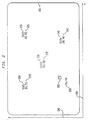
- the display is shown by the rectangle with curved corners (200). Positions on the display (200) are relative to a two-dimensional coordinate system X (280) and Y (290).
- the display (200) contains nodes (210, 220 230, 240, 925) that represent classes. These nodes are rendered in the form of text, shown as Text1, Text2, Text3, and Text:hp1.n:ehp1. (210, 220, 230, 240, 925).
- node 925 is any graphical node, e.g., an icon, text, picture, symbol, mark, etc.
- the text identifies a class; e.g., it is the name of the corresponding class.
- each node (210, 220, 230, 240, 925) has a position. This position is represented in Figure 2 by a coordinate pair in parentheses (215, 225, 235, 245, 926). Preferably, these positions (215, 225, 235, 245, 926) do not appear on the display (200) and are included in this figure to reference the position of the associated node (210, 220, 230, 240, 925).
- Node 230 represents a node on the display (200) with a position (235) at or near the center of the display (200).
- Figure 3 shows an object-oriented program that generates events processed by a novel visualizing program and rendered on a graphical interface.
- Program 300 is any object-oriented program known in the art.
- This Object-Oriented Program (300) contains classes and objects. One such class is indicated by 360, and two such objects are indicated by 361 and 362.
- Operating with the Object-Oriented Program (300) at run-time is an Event Collector (310).
- This Event Collector (310) collects events and passes them to the Event Transmitter (330).
- the Event Transmitter (330) sends events to the novel Visualizing Program (350).
- the Visualizing Program (350) may execute concurrently with the Object-Oriented Program (300), or it may execute at a later time.
- the Visualizing Program (350) need not execute on the same computer system as the Object-Oriented Program (300).
- the Event Transmitter (330) may hold events until the Visualizing Program (300) executes. Event Transmitters (330) are known.
- the Visualizing Program (350) receives events from the Event Transmitter (330) and organizes them in an Execution Model (370).
- the Visualization Algorithm (380) analyzes the Execution Model (370).
- the Visualization Algorithm (380) accesses (354) the Execution Model (370) and the graphical interface display (390).
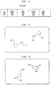
- FIG 4 is a block diagram of a data structure showing the content of an event.
- An Event (400) contains a Type (430), an Object Name (415), a Time Stamp (420), a Method Name (425), and a Class Name (410).
- An event may contain other information.
- the Event (400) is sent to the Visualizing Program (350) by the Event Transmitter (330).
- information is passed from the running Object-Oriented Program 300 (fig. 3) to the novel Visualizing Program 350 (fig. 3).
- An Event Collector 310 (fig. 3) in the Object-Oriented Program 300 (fig. 3) collects Events 400 (fig. 4) and transmits them using the Event Transmitter 330 (fig. 3) to the Visualizing Program 350 (fig. 3).
- the Events 400 (fig. 4) are small data structures with information about the running Object-Oriented Program 300 (fig. 3).
- Two Events 400 (fig. 3) are produced every time a message 190 (fig. 1) is processed by the Object-Oriented Program 300 (fig. 3).
- the first Event 400 (fig. 4) is produced at the start of message 190 (fig. 1) processing and the second Event 400 (fig. 4) is produced at the end of message 190 (fig. 1) processing.
- Every Event 400 (fig. 4) contains the following information:
- the Events 400 are transmitted (using the Event Transmitter 330 (fig. 3)) from the Object-Oriented Program 300 (fig. 3) to the Visualizing Program 350 (fig. 3).
- Events are organized in the Execution Model 370 (fig. 3) of this Visualizing Program 350 (fig. 3) in a special way to reflect different types of interaction between the classes 160, 170 (fig. 1) of the Object-Oriented Program 300 (fig. 3).
- This Execution Model 370 (fig. 3) is changing continuously as new Events 400 (fig. 4) are transmitted to the Event Transmitter 330 (fig. 3) to the Visualizing Program 350 (fig. 3) causing the degree of interaction between the classes 160, 170 (fig. 1) to change.
- the Visualization Algorithm 380 (fig. 3) is a dynamic iterative algorithm that shows the classes 160, 170 (fig. 1) of the object-oriented program 300 (fig. 3) as floating nodes 210, 220, 230, 240, 925 (fig. 2). These nodes 210, 220, 230, 240, 925 are displayed on a computer display 200 (fig. 2).
- a node on the display is shown as text 210, 220, 230, 240 (fig. 2) with the corresponding Class Name 410 (fig. 4).
- a node on the display may be depicted graphically 925 (fig. 2).
- the higher the degree of interaction between two classes 160, 170 (fig. 1), the closer their respective nodes 210, 220, 230, 240, 925 (fig. 2) will be depicted on the display 200 (fig. 2).
- the node 210, 220, 230, 240, 925 (fig. 2) placement by the Visualization Algorithm 380 (fig. 3) is based on a spring-based algorithm.
- FIG. 11 shows the Visualization Algorithm 380 (fig. 3).
- a new Event 400 (fig. 4) arrives in the Visualizing Program 350 (fig. 3) from the Event Transmitter 330 (fig. 3).
- the Execution Model 370 (fig. 3), which records the interaction between any pairs of classes 160, 170 (fig. 1), is updated at step 1120 (fig. 11).
- a class 160 (fig. 1) is used for the first time (which is determined by step 1130 (fig. 11))
- a new node 230 (fig. 2) is created at step 1140 (fig. 11) in the center of the display (fig. 2).
- the degree of interaction for every possible pair of classes 160, 170 (fig. 1) (ni, nj) is processed.
- the degree of interaction for the next pair of classes is obtained 354 (fig. 3) from the Execution Model 370 (fig. 3) and then processed. If there are more pairs of nodes to process (which is determined at step 1160 (fig. 11)), then node positions are calculated and nodes are repositioned at step 1170 (fig. 11).
- Nodes represent classes in an object-oriented program.
- the nodes 710 and 760 (Text1) represent the same class in both figures 7a and 7b.
- the nodes 730 and 780 (Text3) represent the same class in both figures 7a and 7b.
- Figure 7a shows Display1 (700) with two nodes (710, 730). Each node is rendered as text (Text1, Text3) that identifies the associated class. Each node has an associated position (715, 735) shown in parentheses. The position information is not shown on the display and is depicted in this figure only to indicate the position of the associated node.
- Figure 7b shows a Display2 (750) with two nodes (760, 780). Each node has an associated position (765, 785) shown in parentheses. The position information is not shown on the display and is depicted in this figure to reference the position of the associated node.
- FIG 7a and figure 7b show nodes and their positions at two consecutive points in time.
- Display1 (700) may occur before or after Display2 (750).
- the four nodes 810, 820, 830, 840 are rendered on a graphical display 800 (fig. 8) with text Text1, Text2, Text3, Text:hp1.n:ehp1., respectively.
- the degrees of interaction between the nodes 810, 820, 830, 840 (fig. 8) can be shown on the display 800 (fig. 8) as connecting lines 850 (fig. 8) between the respective nodes. If desired, color or thickness of these lines 850 (fig. 8) can be used to represent the corresponding degree of interaction.
- the four nodes 910, 920, 930, 940 are rendered on a graphical display 900 (fig. 9) with text Text1, Text2, Text3, Text n , respectively.
- the nodes represent classes that are on the current call stack of the object-oriented program.
- the nodes 910, 920, 930, 940 represent classes, and the text identifies a class. More nodes that are not on the current call stack may appear on the display; they are not shown in this figure.
- the line segments 950, 960 (fig. 9) connect all nodes on the current call stack in the order of the message sends.
- the last line segment 960 (fig. 9) represents the last message send on the call stack, and it is rendered differently than the other line segments.
- a graphical interface display 1000 (fig. 10) is shown with nodes 1010, 1020, 1030, 1040 (fig. 10) that represent classes of an object-oriented program. Each node is rendered as text Text1, Text2, Text3, Text n . that identifies the associated class.
- the node represented by 1030 (Text3 with a strikeout line through the text) represents a node that is being removed from the display 1000 (fig. 10).
- nodes 1030 (fig. 10) disappear from the display 1000 (fig. 10).
- the node 1030 (fig. 10) of a given class will disappear if no instances of this class remain in the Object-Oriented Program 300 (fig. 3).
Landscapes
- Engineering & Computer Science (AREA)
- Theoretical Computer Science (AREA)
- Quality & Reliability (AREA)
- Physics & Mathematics (AREA)
- General Engineering & Computer Science (AREA)
- General Physics & Mathematics (AREA)
- Computer Hardware Design (AREA)
- Data Mining & Analysis (AREA)
- Stored Programmes (AREA)
- Debugging And Monitoring (AREA)
- User Interface Of Digital Computer (AREA)
- Digital Computer Display Output (AREA)
Applications Claiming Priority (2)
| Application Number | Priority Date | Filing Date | Title |
|---|---|---|---|
| US312849 | 1994-09-27 | ||
| US08/312,849 US5592600A (en) | 1994-09-27 | 1994-09-27 | Animated display showing execution of object-oriented programs |
Publications (1)
| Publication Number | Publication Date |
|---|---|
| EP0704798A1 true EP0704798A1 (de) | 1996-04-03 |
Family
ID=23213285
Family Applications (1)
| Application Number | Title | Priority Date | Filing Date |
|---|---|---|---|
| EP95113293A Withdrawn EP0704798A1 (de) | 1994-09-27 | 1995-08-24 | Lebendig gestaltete Darstellung der Ausführung von objektorientierten Programmen |
Country Status (3)
| Country | Link |
|---|---|
| US (1) | US5592600A (de) |
| EP (1) | EP0704798A1 (de) |
| JP (1) | JP3594204B2 (de) |
Cited By (1)
| Publication number | Priority date | Publication date | Assignee | Title |
|---|---|---|---|---|
| EP0923028A3 (de) * | 1997-12-09 | 2001-09-12 | Sun Microsystems, Inc. | Verfahren zur Objektheapanalyse zum Nachweis von Speicherverlusten und sonstigen Laufzeitinformationen |
Families Citing this family (42)
| Publication number | Priority date | Publication date | Assignee | Title |
|---|---|---|---|---|
| US5796398A (en) * | 1996-03-08 | 1998-08-18 | Ncr Corporation | Information visualization icons |
| US5918053A (en) * | 1996-12-19 | 1999-06-29 | International Business Machines Corp. | Method and system for diagraming collaborations deduced from small talkcode using a design virtual machine |
| JP3349057B2 (ja) * | 1997-02-24 | 2002-11-20 | 株式会社東芝 | マルチタスク処理装置、マルチタスク処理方法およびマルチタスク処理表示方法 |
| JPH1124901A (ja) * | 1997-06-27 | 1999-01-29 | Internatl Business Mach Corp <Ibm> | プログラム情報の解析・表示方法およびシステム |
| US6314564B1 (en) | 1997-11-17 | 2001-11-06 | Agere Systems Guardian Corp. | Method for resolving arbitrarily complex expressions at link-time |
| US6205576B1 (en) | 1998-06-05 | 2001-03-20 | Nortel Networks Limited | Method and apparatus for identifying indirect messaging relationships between software entities |
| US6233729B1 (en) | 1998-10-29 | 2001-05-15 | Nortel Networks Limited | Method and apparatus for identifying dynamic structure and indirect messaging relationships between processes |
| US6346945B1 (en) | 1998-12-28 | 2002-02-12 | Klocwork Solutions | Method and apparatus for pattern-based flowcharting of source code |
| US6480203B1 (en) | 1999-03-19 | 2002-11-12 | Corel Inc. | System and method for processing an event of a graphical object |
| US6469715B1 (en) | 1999-03-19 | 2002-10-22 | Corel Inc. | System and method for controlling the operation of a graphical object using a project |
| US6549199B1 (en) | 1999-03-19 | 2003-04-15 | Corel Inc. | System and method for adjusting a graphical object |
| US6469716B1 (en) | 1999-03-19 | 2002-10-22 | Corel Inc. | System and method for processing data for a graphical object |
| US7114149B2 (en) * | 1999-10-05 | 2006-09-26 | Borland Software Corporation | Navigation links in generated documentation |
| US7403984B2 (en) * | 2000-02-01 | 2008-07-22 | Asyst Technologies, Inc. | Automated tool management in a multi-protocol environment |
| US8028049B1 (en) * | 2000-02-01 | 2011-09-27 | Peer Intellectual Property Inc. | Apparatus and method for web-based tool management |
| US9785140B2 (en) * | 2000-02-01 | 2017-10-10 | Peer Intellectual Property Inc. | Multi-protocol multi-client equipment server |
| US7873428B2 (en) * | 2005-04-15 | 2011-01-18 | PEER Intellectual Property, Inc. | Automated job management |
| EP1290550A1 (de) * | 2000-04-21 | 2003-03-12 | Togethersoft Corporation | Diagrammsteuerung von software in einem versionssteuerungssystem |
| US7024631B1 (en) * | 2000-05-12 | 2006-04-04 | National Instruments Corporation | System and method for enabling graphical program polymorphism |
| US7110936B2 (en) * | 2001-02-23 | 2006-09-19 | Complementsoft Llc | System and method for generating and maintaining software code |
| US20040015879A1 (en) * | 2001-03-23 | 2004-01-22 | International Business Machines Corporation | Method and apparatus for tracing details of a program task |
| US7756963B2 (en) * | 2001-07-05 | 2010-07-13 | PEER Intellectual Property, Inc. | Automated tool management in a multi-protocol environment |
| US6862727B2 (en) * | 2001-08-24 | 2005-03-01 | Formfactor, Inc. | Process and apparatus for adjusting traces |
| US6678876B2 (en) * | 2001-08-24 | 2004-01-13 | Formfactor, Inc. | Process and apparatus for finding paths through a routing space |
| US7310780B2 (en) * | 2003-08-14 | 2007-12-18 | International Business Machines Corporation | Methods, systems and computer program products for visually tethering related graphical objects |
| US7546587B2 (en) * | 2004-03-01 | 2009-06-09 | Microsoft Corporation | Run-time call stack verification |
| JP2006185211A (ja) * | 2004-12-28 | 2006-07-13 | Internatl Business Mach Corp <Ibm> | プログラム解析装置、テスト実行装置、その解析方法及びプログラム |
| US20080127102A1 (en) * | 2006-09-14 | 2008-05-29 | Glen J Anderson | Technique to visually present memory location and usage during code execution |
| US8640086B2 (en) * | 2006-12-29 | 2014-01-28 | Sap Ag | Graphical user interface system and method for presenting objects |
| US10127129B2 (en) * | 2007-02-27 | 2018-11-13 | Red Hat, Inc. | Non-invasive time-based profiling tool |
| US8413112B2 (en) * | 2007-05-10 | 2013-04-02 | International Business Machines Corporation | Visualization of information using landmasses |
| US7851298B2 (en) * | 2007-10-29 | 2010-12-14 | Hynix Semiconductor Inc. | Method for fabricating transistor in a semiconductor device utilizing an etch stop layer pattern as a dummy pattern for the gate electrode formation |
| US8490055B2 (en) | 2010-09-17 | 2013-07-16 | Ca, Inc. | Generating dependency maps from dependency data |
| US8438427B2 (en) | 2011-04-08 | 2013-05-07 | Ca, Inc. | Visualizing relationships between a transaction trace graph and a map of logical subsystems |
| US8782614B2 (en) | 2011-04-08 | 2014-07-15 | Ca, Inc. | Visualization of JVM and cross-JVM call stacks |
| US9202185B2 (en) | 2011-04-08 | 2015-12-01 | Ca, Inc. | Transaction model with structural and behavioral description of complex transactions |
| US8516301B2 (en) | 2011-04-08 | 2013-08-20 | Ca, Inc. | Visualizing transaction traces as flows through a map of logical subsystems |
| US20120272168A1 (en) * | 2011-04-20 | 2012-10-25 | Panafold | Methods, apparatus, and systems for visually representing a relative relevance of content elements to an attractor |
| US20150135048A1 (en) * | 2011-04-20 | 2015-05-14 | Panafold | Methods, apparatus, and systems for visually representing a relative relevance of content elements to an attractor |
| US8789181B2 (en) | 2012-04-11 | 2014-07-22 | Ca, Inc. | Flow data for security data loss prevention |
| JP6061273B2 (ja) | 2013-03-29 | 2017-01-18 | インターナショナル・ビジネス・マシーンズ・コーポレーションInternational Business Machines Corporation | 表示装置、表示方法、及びプログラム |
| US9836183B1 (en) * | 2016-09-14 | 2017-12-05 | Quid, Inc. | Summarized network graph for semantic similarity graphs of large corpora |
Citations (1)
| Publication number | Priority date | Publication date | Assignee | Title |
|---|---|---|---|---|
| EP0261853A2 (de) * | 1986-09-25 | 1988-03-30 | Tektronix, Inc. | System zur Überwachung von Operationen von Objektorientierten Programmen |
Family Cites Families (12)
| Publication number | Priority date | Publication date | Assignee | Title |
|---|---|---|---|---|
| DE261853C (de) * | ||||
| US4821220A (en) * | 1986-07-25 | 1989-04-11 | Tektronix, Inc. | System for animating program operation and displaying time-based relationships |
| US5206951A (en) * | 1987-08-21 | 1993-04-27 | Wang Laboratories, Inc. | Integration of data between typed objects by mutual, direct invocation between object managers corresponding to object types |
| US5233688A (en) * | 1988-03-31 | 1993-08-03 | Kabushiki Kaisha Toshiba | Method and apparatus for process monitoring and method of constructing network diagram for process monitoring |
| US4982344A (en) * | 1988-05-18 | 1991-01-01 | Xerox Corporation | Accelerating link creation |
| JP2759121B2 (ja) * | 1988-06-27 | 1998-05-28 | 日本電信電話株式会社 | 関連画像情報へ誘導するためのナビゲータの生成表示方法及びその装置 |
| US5047959A (en) * | 1988-09-13 | 1991-09-10 | Square D Company | Flexible data display |
| US4953106A (en) * | 1989-05-23 | 1990-08-28 | At&T Bell Laboratories | Technique for drawing directed graphs |
| US5161225A (en) * | 1989-10-23 | 1992-11-03 | International Business Machines Corporation | Persistent stream for processing time consuming and reusable queries in an object oriented database management system |
| US5212771A (en) * | 1990-04-27 | 1993-05-18 | Bachman Information Systems, Inc. | System for establishing concurrent high level and low level processes in a diagram window through process explosion and implosion subsystems |
| US5187786A (en) * | 1991-04-05 | 1993-02-16 | Sun Microsystems, Inc. | Method for apparatus for implementing a class hierarchy of objects in a hierarchical file system |
| US5440742A (en) * | 1991-05-10 | 1995-08-08 | Siemens Corporate Research, Inc. | Two-neighborhood method for computing similarity between two groups of objects |
-
1994
- 1994-09-27 US US08/312,849 patent/US5592600A/en not_active Expired - Fee Related
-
1995
- 1995-08-24 EP EP95113293A patent/EP0704798A1/de not_active Withdrawn
- 1995-09-21 JP JP24271095A patent/JP3594204B2/ja not_active Expired - Fee Related
Patent Citations (2)
| Publication number | Priority date | Publication date | Assignee | Title |
|---|---|---|---|---|
| EP0261853A2 (de) * | 1986-09-25 | 1988-03-30 | Tektronix, Inc. | System zur Überwachung von Operationen von Objektorientierten Programmen |
| US4885717A (en) | 1986-09-25 | 1989-12-05 | Tektronix, Inc. | System for graphically representing operation of object-oriented programs |
Non-Patent Citations (2)
| Title |
|---|
| "Visual Feedback in an Object Oriented Debugger", IBM TECHNICAL DISCLOSURE BULLETIN, vol. 27, no. 04B, April 1994 (1994-04-01), NEW YORK US, pages 341 * |
| GAURAV MARWAHA ET AL.: "Parallel Program Visualisation for a Message-Passing System", 1994 IEEE 13TH ANNUAL INTERNATIONAL PHOENIX CONFERENCE ON COMPUTERS AND COMMUNICATIONS, 15 April 1994 (1994-04-15), PHOENIX, ARIZONA, U.S.A., pages 200 - 205, XP000462557 * |
Cited By (1)
| Publication number | Priority date | Publication date | Assignee | Title |
|---|---|---|---|---|
| EP0923028A3 (de) * | 1997-12-09 | 2001-09-12 | Sun Microsystems, Inc. | Verfahren zur Objektheapanalyse zum Nachweis von Speicherverlusten und sonstigen Laufzeitinformationen |
Also Published As
| Publication number | Publication date |
|---|---|
| JP3594204B2 (ja) | 2004-11-24 |
| JPH08115231A (ja) | 1996-05-07 |
| US5592600A (en) | 1997-01-07 |
Similar Documents
| Publication | Publication Date | Title |
|---|---|---|
| US5592600A (en) | Animated display showing execution of object-oriented programs | |
| EP0654735B1 (de) | Vorrichtung und Verfahren zur Analyse eines Verarbeitungsystems | |
| US5689717A (en) | Method and apparatus for the placement of annotations on a display without overlap | |
| US6219826B1 (en) | Visualizing execution patterns in object-oriented programs | |
| KR100228938B1 (ko) | 데이타 프로세싱 시스템 및 프로그램 생성방법 | |
| US6983357B2 (en) | Hardware accelerator for an object-oriented programming language | |
| US6330659B1 (en) | Hardware accelerator for an object-oriented programming language | |
| EP0764904A1 (de) | Dreidimensionale Echtzeitüberwachung von Prozessattributen | |
| EP0360769A2 (de) | Verfahren zur impliziten Verteilung von gemeinsamen Werten zwischen mitteilenden aktiven Objekten | |
| JP2006504156A (ja) | リアルタイム・システム制御のためのコンポーネント・モデル | |
| CN110990431A (zh) | 一种实现中国地图和折线图数据同步联动轮播的方法 | |
| Snowdon et al. | The AVIARY VR-system. a prototype implementation | |
| US6816914B1 (en) | Callable graphical programming language | |
| Phillips | Geomview manual | |
| New et al. | Adding graphics and animation to Estelle | |
| Müller et al. | The program animation system PASTIS | |
| Demetrescu et al. | Visualization in algorithm engineering: Tools and techniques | |
| Noble et al. | Tarraingím: A Program Animation Environment | |
| KR100277706B1 (ko) | 서비스개발환경에서 에스아이비 응용 프로그램 수행 방법 | |
| Arra | Object-oriented data structure animation | |
| CN120745046A (zh) | 一种通过图形化设计系统模型时间行为的方法 | |
| BATTERSBY et al. | An MSDOST™ based Graphics Library for PC hosted Transputer Systems | |
| Aoki | The prototyping of GeoManager: A geometric algorithm manipulation system | |
| Lobe et al. | The Object-Oriented Components of the Enterprise Parallel Programming Environment. | |
| Barth et al. | UGRAF3: A graphic system for process and modelling |
Legal Events
| Date | Code | Title | Description |
|---|---|---|---|
| PUAI | Public reference made under article 153(3) epc to a published international application that has entered the european phase |
Free format text: ORIGINAL CODE: 0009012 |
|
| AK | Designated contracting states |
Kind code of ref document: A1 Designated state(s): DE FR GB |
|
| STAA | Information on the status of an ep patent application or granted ep patent |
Free format text: STATUS: THE APPLICATION HAS BEEN WITHDRAWN |
|
| 18W | Application withdrawn |
Withdrawal date: 19960820 |