EP0704867B1 - Auslösevorrichtung mit mindestens einem Stromwandler - Google Patents
Auslösevorrichtung mit mindestens einem Stromwandler Download PDFInfo
- Publication number
- EP0704867B1 EP0704867B1 EP95410110A EP95410110A EP0704867B1 EP 0704867 B1 EP0704867 B1 EP 0704867B1 EP 95410110 A EP95410110 A EP 95410110A EP 95410110 A EP95410110 A EP 95410110A EP 0704867 B1 EP0704867 B1 EP 0704867B1
- Authority
- EP
- European Patent Office
- Prior art keywords
- current
- shunt
- circuit
- magnetic
- secondary winding
- Prior art date
- Legal status (The legal status is an assumption and is not a legal conclusion. Google has not performed a legal analysis and makes no representation as to the accuracy of the status listed.)
- Expired - Lifetime
Links
- 238000004804 winding Methods 0.000 claims description 31
- 239000004020 conductor Substances 0.000 claims description 23
- 230000004907 flux Effects 0.000 description 6
- 238000005259 measurement Methods 0.000 description 5
- 239000007787 solid Substances 0.000 description 4
- 239000000696 magnetic material Substances 0.000 description 3
- 230000001105 regulatory effect Effects 0.000 description 3
- 230000033228 biological regulation Effects 0.000 description 2
- 238000009795 derivation Methods 0.000 description 2
- 238000010586 diagram Methods 0.000 description 2
- 230000000694 effects Effects 0.000 description 2
- 150000002505 iron Chemical class 0.000 description 2
- 230000005355 Hall effect Effects 0.000 description 1
- 238000012550 audit Methods 0.000 description 1
- 238000001816 cooling Methods 0.000 description 1
- 230000007423 decrease Effects 0.000 description 1
- 238000010438 heat treatment Methods 0.000 description 1
- 239000012535 impurity Substances 0.000 description 1
- 230000006698 induction Effects 0.000 description 1
- 229920006395 saturated elastomer Polymers 0.000 description 1
Images




Classifications
-
- H—ELECTRICITY
- H01—ELECTRIC ELEMENTS
- H01F—MAGNETS; INDUCTANCES; TRANSFORMERS; SELECTION OF MATERIALS FOR THEIR MAGNETIC PROPERTIES
- H01F27/00—Details of transformers or inductances, in general
-
- H—ELECTRICITY
- H01—ELECTRIC ELEMENTS
- H01F—MAGNETS; INDUCTANCES; TRANSFORMERS; SELECTION OF MATERIALS FOR THEIR MAGNETIC PROPERTIES
- H01F38/00—Adaptations of transformers or inductances for specific applications or functions
- H01F38/08—High-leakage transformers or inductances
-
- H—ELECTRICITY
- H01—ELECTRIC ELEMENTS
- H01F—MAGNETS; INDUCTANCES; TRANSFORMERS; SELECTION OF MATERIALS FOR THEIR MAGNETIC PROPERTIES
- H01F38/00—Adaptations of transformers or inductances for specific applications or functions
- H01F38/20—Instruments transformers
- H01F38/22—Instruments transformers for single phase AC
- H01F38/28—Current transformers
- H01F38/30—Constructions
-
- H—ELECTRICITY
- H01—ELECTRIC ELEMENTS
- H01H—ELECTRIC SWITCHES; RELAYS; SELECTORS; EMERGENCY PROTECTIVE DEVICES
- H01H71/00—Details of the protective switches or relays covered by groups H01H73/00 - H01H83/00
- H01H71/10—Operating or release mechanisms
- H01H71/12—Automatic release mechanisms with or without manual release
- H01H71/123—Automatic release mechanisms with or without manual release using a solid-state trip unit
- H01H71/125—Automatic release mechanisms with or without manual release using a solid-state trip unit characterised by sensing elements, e.g. current transformers
Definitions
- current transformers provide the electrical energy required to operate at its own current in electrical circuits, or associated electronics.
- Current transformers are installed on conductors of a power circuit to be protected. They provide electronic circuits with triggering of low intensity secondary currents proportional to currents very strong primaries.
- the alternating secondary currents are rectified and regulated in order to to supply continuous supply voltages to the trigger circuits.
- the consumption of the circuits being stable or little variable, the excess energy supplied by the transformers is dissipated by regulating circuits and by the transformers themselves.
- the minimum secondary operating current corresponds to the consumption of trip circuits.
- operation must usually be ensured between 0.1 and 10 times the rated current.
- the devices must include large transformers capable of dissipating excess energy transformed into heat. For the same reasons the components power electronics of the control circuits must be oversized and fixed on bulky cooling devices.
- Saturated iron current transformers reduce the secondary current to high current level and limit the power supplied to the regulation circuits.
- the operation of saturated iron transformers does not resolve effectively the problems of size and heating over the entire operating range of the triggering device.
- the object of the invention is a triggering device comprising at least one current transformer providing reduced power at high primary current.
- the transformer has a magnetic shunt arranged in derivation on the part of the main magnetic circuit constituting the core of the secondary winding, the magnetic shunt comprising a total or partial air gap locally reducing the section of said shunt.
- the current response of said transformer is not linear over the entire range of operation.
- the magnetic shunt is positioned between the primary conductor and the secondary winding.
- the section of the magnetic shunt near the air gap is greater than the section of the magnetic circuit at the location of the core the secondary winding.
- the size of the air gap can vary in different places of the shunt section.
- the air gap can be located substantially in the middle of the magnetic shunt or between the shunt and the main magnetic circuit.
- the shunt and the main magnetic circuit form the same room.
- At least one secondary winding has shielding electromagnetic.
- said transformer current essentially providing electrical power for operation, is associated with a current measurement sensor.
- the current measurement sensor is preferably a toroid of Rogowski.
- FIG. 1 represents a block diagram of a trigger device installed in a circuit breaker.
- FIG. 2 represents a known current transformer.
- FIG. 3 represents a current transformer according to an embodiment of the invention can be part of a trigger device according to Figure 1.
- FIGs 4 and 5 show two variants of current transformers according to Figure 3.
- FIG. 6 represents the curves of the current responses of the transformers of FIGS. 2 and 3.
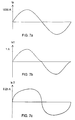
- Figures 7a, 7b and 7c illustrate the currents for a particular point on curve 6.
- Figures 8 to 11 show air gap variants of current transformers Figures 3 to 5.
- FIG. 12 shows a transformer according to an embodiment of the invention associated with a torus of rogowski.
- FIG. 1 shows a trigger device installed in a circuit breaker to protect an electrical network 1 against overloads or short-circuits.
- Contacts 2 of the circuit breaker controlled by the trip device, establish or interrupt the current in the network conductors.
- the opening of contacts 2 is controlled by a relay 3.
- the triggering device comprises current transformers 4a, 4b and 4c associated with network conductors to supply the electrical energy necessary for operation of electronic circuits in a processing unit 25.
- the windings current transformers are connected to a supply circuit 5 which rectifies the alternating current supplied by the secondary windings of the transformers and provides one or more regulated DC voltages.
- a first tension continuous V1 is supplied to measuring and processing circuits, respectively 6 and 7, while a second direct voltage V2 supplies the relay 3.
- the processing unit 25 includes relay 3 and circuits 5, 6 and 7.
- Circuit 6 amplifies and activates forms signals representative of the currents of the conductors coming from the sensors 8a, 8b and 8c. Then, it sends them to the processing circuit 7. Circuit 7 sends an order to tripping 9 when the signals representative of the conductor currents exceed predetermined thresholds for predetermined times.
- Sensors 8a, 8b and 8c can be, for example, measuring transformers, Rogowski toroids or Hall effect cells.
- FIG. 2 represents a known current transformer which can be used as transformers 4a, 4b or 4c.
- Said known current transformer has a circuit magnetic 10 and a secondary winding represented by a coil 11 and two wires of output 12.
- the magnetic circuit generally consisting of stacked sheets, surrounds completely a conductor 13 of network 1 where the primary current of the transformer.
- a part 14 of the magnetic circuit 10 passes through the center of the winding secondary and forms the core of the coil 12.
- the transformers 4a, 4b and 4c of the device for triggering the Figure 1 are current transformers comprising a magnetic shunt to gap.
- Figure 3 shows an embodiment of a transformer of this type.
- a shunt magnetic 15, bypassed on the magnetic core 14 of the secondary winding, has an air gap 16.
- Figures 4 and 5 show variants of transformers according to two other modes of realization of the invention.
- the part of the magnetic circuit surrounding the primary conductor has a rounded shape including the magnetic shunt 15.
- the transformer of figure 4 has an air gap located substantially in the middle of the shunt.
- the transformer air gap Figure 5 is located between one end of the shunt and part of the magnetic circuit main 10 connecting an area close to the primary conductor and the core of the winding secondary. In this case the section of the magnetic shunt 15 near the air gap is greater than the section of the magnetic circuit at the location of the core 14 of the winding secondary.
- the main magnetic circuit 10 and the shunt 15 form one piece. Said part may be constituted by stacked sheets or by other magnetic materials.
- a first curve 17 represents the effective current response of a transformer of known type does with no shunt. The shape of curve 17 is almost linear. Secondary current Is is substantially proportional to the primary current Ip.
- a second curve, 18, represents the effective current response of a transformer according to one embodiment of the invention comprising an air gap shunt.
- the secondary currents of the two transformers corresponding to curves 17 and 18, have similar values.
- the response curve 18 of the transformer including an air gap shunt becomes more weak than curve 17 of the transformer without shunt. For example, for a current of 800A the transformer with an air gap shunt, provides a secondary current of the order of 0.25 A (point 19 on curve 18) while the transformer without shunt provides a 0.8 A current.
- the shapes of the primary and secondary currents are illustrated on the curves of FIGS. 7a, 7b and 7 c.
- the sinusoidal primary current Ip having a value of 800 A, crosses the primary of a first transformer according to FIG. 2 and the primary of a second transformer according to Figure 3.
- Figure 7b shows a secondary current Is1 of the first transformer.
- the effective value of the current Is1 is 0.8 A and its shape is substantially sinusoidal.
- Figure 7c shows a secondary current Is2 of the second transformer comprising a magnetic shunt according to an embodiment of the invention.
- the current Is2 is deformed and its value, about 0.25 A, is much lower than that of the current Is1.
- For a primary current Ip 800 A the power dissipated in the secondary winding of the first transformer without shunt is 9 W while the power dissipated in the winding of the second transformer with a magnetic shunt is only of 0.9W.
- the response, of the secondary current Is as a function of the primary current Ip, of the transformers with an air gap shunt depends on the shape, surface and the thickness of the air gap.
- the transformers in Figures 3 to 5 have thick air gaps constant and opening the entire section of shunts 15. However, other forms air gap are possible.
- Figures 8 to 11 show various air gap variants.
- the thickness of the air gap can be variable to improve the response at high level of current.
- Figure 8 shows an air gap with different thickness in different places of the shunt section.
- Figure 9 shows a shunt with a partial air gap.
- a large part of the magnetic circuit of the shunt is cut by the air gap and a small part remains connected.
- the attenuation begins with more primary currents low.
- the magnetic shunt 15 can comprise several air gaps, for example an air gap 16 a total and a partial air gap 16 b as shown in FIG. 10.
- FIG. 11 represents a shunt comprising a complex air gap.
- the air gap includes a first transverse part 21 and a second part 22 and a longitudinal part 23 connecting the first and second transverse parts.
- the effects of the air gap being essentially in the longitudinal part, this arrangement makes it possible to have a large air gap area and a large magnetic flux circulation at high primary current.
- the air gap of the magnetic shunt is generally a notch left in the open air but it can be completely or partially filled with a solid non-magnetic material.
- the air gap of the longitudinal part 23 of the shunt of FIG. 11 comprises a solid non-magnetic component 24. Said solid non-magnetic component prevents impurities from getting into the thickness of the air gap.
- a thin air gap can advantageously consist of a screen made of solid non-magnetic material.
- the primary conductor 13 crosses the magnetic circuit of a transformer according to the invention and the center of a toroid of Rogowski 26.
- the secondary of the first transformer according to the invention supplies electronic circuits and the secondary of the Rogowski torus provides measurement circuits and processing the signal representative of the current flowing in the primary conductor.
- the transformer and Rogowski torus are preferably fixed to each other, for example by overmolding.
- the device of FIG. 12 includes an electromagnetic shielding 27.
- the current transformers of a device according to the invention can have forms very varied.
- the shunt with air gap is arranged between the primary conductor and the secondary winding.
- the secondary winding would then find between the primary conductor and the shunt. This provision can be advantageous depending on the volume allocated to the current transformer.
- a transformer according to the invention may include a magnetic circuit with a core of the secondary winding comprising a partial or total air gap and a magnetic shunt also comprising a partial or total air gap. This arrangement may allow better distribute the magnetic flux between the shunt and the core according to the value of the current primary.
- the transformers have a single secondary winding, and only one shunt but the invention also applies to devices comprising transformers with several secondary windings and / or several shunts.
Landscapes
- Engineering & Computer Science (AREA)
- Power Engineering (AREA)
- Transformers For Measuring Instruments (AREA)
- Breakers (AREA)
- Emergency Protection Circuit Devices (AREA)
- Measuring Instrument Details And Bridges, And Automatic Balancing Devices (AREA)
Claims (10)
- Auslösevorrichtung mitdadurch gekennzeichnet, daß der Wandler einen magnetischen Nebenschlußzweig (15) umfaßt, der parallel zu dem, den Kern der Sekundärwicklung bildenden Teil (14) des Hauptmagnetkreises geführt ist, wobei der magnetische Nebenschlußzweig (15) einen, den Querschnitt des genannten Nebenschlußzweigs örtlich vermindernden, Voll- oder Teilluftspalt (16) aufweist.mindestens einem Stromwandler (4a, 4b, 4c), der einem, von einem Primärstrom (Ip) durchflossenen Leiter (13) eines zu schützenden Stromkreises (1) zugeordnet ist und einen, um den Leiter des zu schützenden Stromkreises geführten Hauptmagnetkreis (10) sowie mindestens eine Sekundärwicklung (11, 12) umfaßt, wobei ein Teil (14) des Hauptmagnetkreises den Kern der Sekundärwicklung (11) bildet, undeiner, an die genannte Sekundärwicklung des Stromwandlers angeschlossenen Verarbeitungseinheit (25),
- Vorrichtung nach Anspruch 1, dadurch gekennzeichnet, daß der magnetische Nebenschlußzweig zwischen dem Primärleiter (13) und der Sekundärwicklung (11) angeordnet ist.
- Vorrichtung nach einem der Ansprüche 1 und 2, dadurch gekennzeichnet, daß die Breite des Luftspalts (16) variieren kann.
- Vorrichtung nach irgendeinem der Ansprüche 1 bis 3, dadurch gekennzeichnet, daß der Querschnitt des magnetischen Nebenschlußzweigs (15) im Bereich des Luftspalts größer ist als der Querschnitt des Magnetkreises im Bereich des Kerns (14) der Sekundärwicklung.
- Vorrichtung nach irgendeinem der Ansprüche 1 bis 4, dadurch gekennzeichnet, daß der Luftspalt (16) annähernd in der Mitte des magnetischen Nebenschlußzweigs (15) ausgebildet ist.
- Vorrichtung nach irgendeinem der Ansprüche 1 bis 4, dadurch gekennzeichnet, daß der Luftspalt (16) zwischen dem magnetischen Nebenschlußzweig (15) und dem Hauptmagnetkreis (10) ausgebildet ist.
- Vorrichtung nach irgendeinem der Ansprüche 1 bis 6, dadurch gekennzeichnet, daß der Nebenschlußzweig (15) und der Hauptmagnetkreis (10) einstückig ausgeführt sind.
- Vorrichtung nach irgendeinem der Ansprüche 1 bis 7, dadurch gekennzeichnet, daß sie einen an eine Stromversorgungsschaltung (5) der Verarbeitungseinheit (25) angeschlossenen Stromwandler (4a, 4b, 4c) sowie einen, an eine Meßschaltung (6) der Verarbeitungseinheit angeschlossenen Meßstromwandler (8a, 8b, 8c, 26) umfaßt, wobei der Stromwandler dem Meßstromwandler (8a, 8b, 8c, 26) des gleichen Leiters (13) des zu schützenden Stromkreises zugeordnet ist
- Vorrichtung nach Anspruch 8, dadurch gekennzeichnet, daß der Meßstromwandler (8a, 8b, 8c, 26) als Rogowskispule ausgeführt ist.
- Vorrichtung nach Anspruch 1, dadurch gekennzeichnet, daß mindestens eine Sekundärwicklung eine elektromagnetische Abschirmung (27) aufweist.
Applications Claiming Priority (2)
| Application Number | Priority Date | Filing Date | Title |
|---|---|---|---|
| FR9411814A FR2725320B1 (fr) | 1994-09-29 | 1994-09-29 | Dispositif de declenchement comportant au moins un transformateur de courant |
| FR9411814 | 1994-09-29 |
Publications (2)
| Publication Number | Publication Date |
|---|---|
| EP0704867A1 EP0704867A1 (de) | 1996-04-03 |
| EP0704867B1 true EP0704867B1 (de) | 1999-12-01 |
Family
ID=9467528
Family Applications (1)
| Application Number | Title | Priority Date | Filing Date |
|---|---|---|---|
| EP95410110A Expired - Lifetime EP0704867B1 (de) | 1994-09-29 | 1995-09-19 | Auslösevorrichtung mit mindestens einem Stromwandler |
Country Status (9)
| Country | Link |
|---|---|
| US (1) | US5726846A (de) |
| EP (1) | EP0704867B1 (de) |
| JP (1) | JP3868522B2 (de) |
| KR (1) | KR100337677B1 (de) |
| CN (1) | CN1052103C (de) |
| DE (1) | DE69513612T2 (de) |
| ES (1) | ES2139865T3 (de) |
| FR (1) | FR2725320B1 (de) |
| MY (1) | MY113940A (de) |
Cited By (1)
| Publication number | Priority date | Publication date | Assignee | Title |
|---|---|---|---|---|
| DE102008049432A1 (de) | 2008-09-25 | 2010-04-01 | Siemens Aktiengesellschaft | Leistungsschalter und Stromwandler für einen Leistungsschalter |
Families Citing this family (44)
| Publication number | Priority date | Publication date | Assignee | Title |
|---|---|---|---|---|
| GB9612504D0 (en) * | 1996-06-14 | 1996-08-14 | Smiths Industries Ltd | Current transformer assemblies |
| DE19706019A1 (de) * | 1997-02-07 | 1998-08-13 | Siemens Ag | Niederspannungs-Leistungsschalter mit wahlweise einbaubarem Meßwandler |
| US6094044A (en) * | 1998-05-07 | 2000-07-25 | Airpax Corporation, Llc | AC current sensor having high accuracy and large bandwidth |
| FR2802017B1 (fr) * | 1999-12-03 | 2004-05-14 | Schneider Electric Ind Sa | Appareillage de coupure triphase de forte intensite a deux poles jumeles par phase, muni de circuits magnetiques de compensation |
| US6433981B1 (en) | 1999-12-30 | 2002-08-13 | General Electric Company | Modular current sensor and power source |
| US6459349B1 (en) | 2000-03-06 | 2002-10-01 | General Electric Company | Circuit breaker comprising a current transformer with a partial air gap |
| DE10240351A1 (de) * | 2002-08-28 | 2004-03-11 | Siemens Ag | Wandleranordnung zur Speisung eines Auslösemagneten |
| CA2538036A1 (en) | 2003-07-23 | 2005-01-27 | Kiyari Co., Ltd. | Tray for frozen food, package of frozen food, package of frozen sushi, and method of thawing frozen sushi |
| US8355230B2 (en) * | 2003-12-08 | 2013-01-15 | Siemens Industry, Inc. | Extended instantaneous protection |
| ITBG20030062A1 (it) * | 2003-12-30 | 2005-06-30 | Abb Service Srl | Dispositivo di alimentazione per un dispositivo di protezione elettronico da impiegarsi in un interruttore di bassa tensione. |
| US8538560B2 (en) * | 2004-04-29 | 2013-09-17 | Rosemount Inc. | Wireless power and communication unit for process field devices |
| US7561387B2 (en) * | 2005-10-19 | 2009-07-14 | Eaton Corporation | Current transformer including a low permeability shunt and a trip device employing the same |
| KR100792484B1 (ko) | 2006-09-13 | 2008-01-08 | 피에스텍주식회사 | 전자식 전력 수급용 계기용 변성기 |
| FR2910173B1 (fr) * | 2006-12-18 | 2012-05-04 | Schneider Electric Ind Sas | Dispositif de mesure de courant a isolation electrique, declencheur electronique, et disjoncteur comportant un tel dispositif |
| FR2910162B1 (fr) * | 2006-12-18 | 2009-12-11 | Schneider Electric Ind Sas | Dispositif de couplage de signal de mesure a isolation electrique et appareil electrique comportant un tel dispositif |
| AT506454B1 (de) * | 2008-02-22 | 2015-10-15 | Egston System Electronics Eggenburg Gmbh | Wandleranordnung |
| CN102084307B (zh) * | 2008-06-17 | 2014-10-29 | 罗斯蒙特公司 | 用于具有低压本质安全钳的现场设备的rf适配器 |
| US8694060B2 (en) | 2008-06-17 | 2014-04-08 | Rosemount Inc. | Form factor and electromagnetic interference protection for process device wireless adapters |
| CN102067048B (zh) * | 2008-06-17 | 2017-03-08 | 罗斯蒙特公司 | 用于具有可变压降的现场设备的rf适配器 |
| US8929948B2 (en) * | 2008-06-17 | 2015-01-06 | Rosemount Inc. | Wireless communication adapter for field devices |
| US8681466B2 (en) | 2009-05-08 | 2014-03-25 | Rockwell Automation Technologies, Inc. | Magnetic core coupling in a current transformer with integrated magnetic actuator |
| US8456782B2 (en) | 2009-05-08 | 2013-06-04 | Rockwell Automation Technologies, Inc. | Cost effective design for a current transformer with an integrated magnetic actuator |
| EP2249368B1 (de) * | 2009-05-08 | 2018-06-13 | Rockwell Automation Technologies, Inc. | Leistungsschaltersystem |
| US8626087B2 (en) * | 2009-06-16 | 2014-01-07 | Rosemount Inc. | Wire harness for field devices used in a hazardous locations |
| US9674976B2 (en) * | 2009-06-16 | 2017-06-06 | Rosemount Inc. | Wireless process communication adapter with improved encapsulation |
| CN101908413B (zh) * | 2010-07-27 | 2012-10-03 | 上海诺雅克电气有限公司 | 给电子装置供电用电流互感器 |
| US10761524B2 (en) | 2010-08-12 | 2020-09-01 | Rosemount Inc. | Wireless adapter with process diagnostics |
| DE102010061766A1 (de) | 2010-11-23 | 2012-01-19 | Siemens Aktiengesellschaft | Schalter, insbesondere Leistungsschalter für Niederspannungen |
| CN102136358B (zh) | 2011-01-13 | 2012-12-19 | 上海诺雅克电气有限公司 | 电子式保护用供电电流互感器 |
| CN102800471A (zh) * | 2011-05-26 | 2012-11-28 | 北京人民电器厂有限公司 | 速饱和电流互感器 |
| DE102011077707B4 (de) | 2011-06-17 | 2015-02-12 | Siemens Aktiengesellschaft | Schalter, insbesondere Leistungsschalter, und Verfahren zum Auslösen eines Schalters |
| DE102011082170A1 (de) | 2011-09-06 | 2013-03-07 | Siemens Aktiengesellschaft | Stromwandler |
| US9310794B2 (en) | 2011-10-27 | 2016-04-12 | Rosemount Inc. | Power supply for industrial process field device |
| JP2013130447A (ja) * | 2011-12-21 | 2013-07-04 | Tamura Seisakusho Co Ltd | 電流センサ用ループコア及び電流センサ |
| US10043627B2 (en) * | 2014-02-06 | 2018-08-07 | Abb S.P.A. | Device for monitoring a current of a primary conductor with respect to a predetermined current threshold, and related trip assembly and switching device |
| CN105336484B (zh) * | 2014-08-06 | 2018-05-01 | 上海电科电器科技有限公司 | 电流互感器 |
| US9953790B1 (en) * | 2016-10-11 | 2018-04-24 | Eaton Intelligent Power Limited | Electrical switching apparatus and sensing assembly therefor |
| US12374487B2 (en) | 2017-04-19 | 2025-07-29 | Narayan Powertech Pvt. Ltd. | Current transformer with current branches on primary conductor |
| KR102003943B1 (ko) * | 2018-01-25 | 2019-07-31 | 엘에스산전 주식회사 | 회로차단기의 파워 변류기 어셈블리 |
| WO2020070316A1 (en) * | 2018-10-05 | 2020-04-09 | Abb Schweiz Ag | Magnetic core arrangement, inductive device and installation device |
| FR3089340B1 (fr) * | 2018-11-29 | 2020-10-30 | Schneider Electric Ind Sas | Transformateur de courant, dispositif de protection et disjoncteur électrique comportant un tel transformateur |
| KR102153970B1 (ko) * | 2018-12-26 | 2020-09-09 | 엘에스일렉트릭(주) | 기중회로차단기의 변류기 |
| DE102022202957A1 (de) * | 2022-03-25 | 2023-09-28 | Siemens Aktiengesellschaft | DC/DC-Wandler |
| CN120615218A (zh) * | 2023-02-10 | 2025-09-09 | 伊顿智能动力有限公司 | 电源单元和断路器 |
Family Cites Families (9)
| Publication number | Priority date | Publication date | Assignee | Title |
|---|---|---|---|---|
| CH412097A (de) * | 1964-06-19 | 1966-04-30 | Oerlikon Maschf | Sättigungsstromwandler |
| DE1638602B1 (de) * | 1967-09-12 | 1970-09-24 | Siemens Ag | Stromwandler mit einem Eisenkernsystem,das einen mittels mindestens eines Luftspaltes gescherten Eisenkern enthaelt |
| US3962661A (en) * | 1975-04-22 | 1976-06-08 | International Telephone And Telegraph Corporation | Magnetically shunted current transformer |
| EP0012629A1 (de) * | 1978-12-19 | 1980-06-25 | Fanuc Ltd. | Drosselspulen |
| SE419009B (sv) * | 1979-10-26 | 1981-07-06 | Sten Trolle | Induktansspole samt sett vid tillverkning av en sadan |
| DE3017368A1 (de) * | 1980-05-07 | 1981-11-12 | Licentia Patent-Verwaltungs-Gmbh, 6000 Frankfurt | Zeilentransformator fuer einen fernsehempfaenger |
| FR2532793A1 (fr) * | 1982-09-08 | 1984-03-09 | Merlin Gerin | Declencheur mixte differentiel et de court-circuit equipe d'un transformateur d'intensite a tore homopolaire commun |
| US4613841A (en) * | 1983-11-30 | 1986-09-23 | General Electric Company | Integrated transformer and inductor |
| GB8617507D0 (en) * | 1986-07-17 | 1986-08-28 | Vickers Systems Ltd | Transformers |
-
1994
- 1994-09-29 FR FR9411814A patent/FR2725320B1/fr not_active Expired - Fee Related
-
1995
- 1995-09-19 EP EP95410110A patent/EP0704867B1/de not_active Expired - Lifetime
- 1995-09-19 US US08/529,975 patent/US5726846A/en not_active Expired - Lifetime
- 1995-09-19 DE DE69513612T patent/DE69513612T2/de not_active Expired - Lifetime
- 1995-09-19 ES ES95410110T patent/ES2139865T3/es not_active Expired - Lifetime
- 1995-09-21 MY MYPI95002794A patent/MY113940A/en unknown
- 1995-09-28 KR KR1019950032520A patent/KR100337677B1/ko not_active Expired - Lifetime
- 1995-09-28 JP JP25148495A patent/JP3868522B2/ja not_active Expired - Lifetime
- 1995-09-29 CN CN95117226A patent/CN1052103C/zh not_active Expired - Fee Related
Cited By (1)
| Publication number | Priority date | Publication date | Assignee | Title |
|---|---|---|---|---|
| DE102008049432A1 (de) | 2008-09-25 | 2010-04-01 | Siemens Aktiengesellschaft | Leistungsschalter und Stromwandler für einen Leistungsschalter |
Also Published As
| Publication number | Publication date |
|---|---|
| KR960012057A (ko) | 1996-04-20 |
| MY113940A (en) | 2002-06-29 |
| DE69513612T2 (de) | 2000-05-31 |
| FR2725320B1 (fr) | 1996-10-31 |
| EP0704867A1 (de) | 1996-04-03 |
| KR100337677B1 (ko) | 2002-10-31 |
| JP3868522B2 (ja) | 2007-01-17 |
| US5726846A (en) | 1998-03-10 |
| CN1052103C (zh) | 2000-05-03 |
| FR2725320A1 (fr) | 1996-04-05 |
| CN1129347A (zh) | 1996-08-21 |
| ES2139865T3 (es) | 2000-02-16 |
| JPH08180790A (ja) | 1996-07-12 |
| DE69513612D1 (de) | 2000-01-05 |
Similar Documents
| Publication | Publication Date | Title |
|---|---|---|
| EP0704867B1 (de) | Auslösevorrichtung mit mindestens einem Stromwandler | |
| EP0326459B1 (de) | Statischer Auslöseschalter mit einer Schaltung mit Sofort-Auslösung, unabhängig von der Versorgungsspannung | |
| EP0791999B1 (de) | Elektronischer Auslöser mit Stromversorgung | |
| FR2568425A1 (fr) | Circuit de coupure de courant en cas de defaut a la terre, avec protection contre l'interruption des conducteurs de neutre et de terre. | |
| EP0061364A1 (de) | Mehrfach einstellbarer Niederspannungsschutzschalter mit Hybridauslöser | |
| EP1736784A1 (de) | Gerät zur Fehlerstrommessung, Auslösemodul und Schaltvorrichtung | |
| EP0099784B1 (de) | Elektronischer, analoger Schalterauslöser zum Überstromschutz eines Wechselstromnetzes | |
| FR2936352A1 (fr) | Disjoncteur et transformateur de courant pour un disjoncteur | |
| EP0677907B1 (de) | Überstromschutzvorrichtung | |
| EP0841670B1 (de) | Stromwandler, Auflöser und Schutzschalter mit solchem Stromwandler | |
| EP0936716B2 (de) | Differentialschutz | |
| EP1260821B1 (de) | Detektionswandler für einen Differentialschutz und mit einem solchen Wandler versehene Schutzeinrichtung | |
| EP3660875A1 (de) | Stromtransformator, schutzvorrichtung und elektrischer trennschalter, die einen solchen transformator umfassen | |
| EP0074297B2 (de) | Hybrider kompensierter Stromwandler | |
| EP2686931B1 (de) | Serieller strombegrenzer mit bohrungen und fenster aufweisenden magnetischem kreis | |
| EP1111750A1 (de) | Schutzvorrichtung gegen elektrische Fehler | |
| EP0739073B1 (de) | Differentialschutz | |
| EP0828265B1 (de) | Stromwandler und Schutzrelais mit einem solchen Wandler | |
| EP1628377B1 (de) | Schutzvorrichtung für elektrische Anlagen gegen Überspannungen einschliesslich einer Funkenstrecke mit Zündschaltung | |
| FR2850803A1 (fr) | Dispositif d'interruption comportant une protection differentielle et une protectiion thermique | |
| EP0813283A1 (de) | Gegen unbeabsichtigtes Auslösen immunisiertes Differentialschutz | |
| EP0295234A1 (de) | Verfahren und Vorrichtung zum Schutz und zur Überwachung von elektrischen Anlagen, die von einem Transformator gespeist werden, und des Transformators selbst | |
| FR2709616A1 (fr) | Disjoncteur différentiel et parasurtenseur. | |
| FR3159713A1 (fr) | Système de protection de circuit électrique | |
| EP0998003B1 (de) | Differentialschutz mit Mehrfachspannungsprüfkreis |
Legal Events
| Date | Code | Title | Description |
|---|---|---|---|
| PUAI | Public reference made under article 153(3) epc to a published international application that has entered the european phase |
Free format text: ORIGINAL CODE: 0009012 |
|
| AK | Designated contracting states |
Kind code of ref document: A1 Designated state(s): DE ES FR GB IT |
|
| 17P | Request for examination filed |
Effective date: 19960924 |
|
| GRAG | Despatch of communication of intention to grant |
Free format text: ORIGINAL CODE: EPIDOS AGRA |
|
| 17Q | First examination report despatched |
Effective date: 19990203 |
|
| GRAG | Despatch of communication of intention to grant |
Free format text: ORIGINAL CODE: EPIDOS AGRA |
|
| GRAH | Despatch of communication of intention to grant a patent |
Free format text: ORIGINAL CODE: EPIDOS IGRA |
|
| GRAH | Despatch of communication of intention to grant a patent |
Free format text: ORIGINAL CODE: EPIDOS IGRA |
|
| RAP1 | Party data changed (applicant data changed or rights of an application transferred) |
Owner name: SCHNEIDER ELECTRIC INDUSTRIES SA |
|
| GRAA | (expected) grant |
Free format text: ORIGINAL CODE: 0009210 |
|
| AK | Designated contracting states |
Kind code of ref document: B1 Designated state(s): DE ES FR GB IT |
|
| REF | Corresponds to: |
Ref document number: 69513612 Country of ref document: DE Date of ref document: 20000105 |
|
| GBT | Gb: translation of ep patent filed (gb section 77(6)(a)/1977) |
Effective date: 20000113 |
|
| REG | Reference to a national code |
Ref country code: ES Ref legal event code: FG2A Ref document number: 2139865 Country of ref document: ES Kind code of ref document: T3 |
|
| ITF | It: translation for a ep patent filed | ||
| PLBE | No opposition filed within time limit |
Free format text: ORIGINAL CODE: 0009261 |
|
| STAA | Information on the status of an ep patent application or granted ep patent |
Free format text: STATUS: NO OPPOSITION FILED WITHIN TIME LIMIT |
|
| 26N | No opposition filed | ||
| REG | Reference to a national code |
Ref country code: GB Ref legal event code: IF02 |
|
| REG | Reference to a national code |
Ref country code: FR Ref legal event code: CJ Ref country code: FR Ref legal event code: CD |
|
| REG | Reference to a national code |
Ref country code: DE Ref legal event code: R084 Ref document number: 69513612 Country of ref document: DE Effective date: 20111228 |
|
| PGFP | Annual fee paid to national office [announced via postgrant information from national office to epo] |
Ref country code: ES Payment date: 20130813 Year of fee payment: 19 |
|
| PGFP | Annual fee paid to national office [announced via postgrant information from national office to epo] |
Ref country code: FR Payment date: 20130916 Year of fee payment: 19 Ref country code: GB Payment date: 20130918 Year of fee payment: 19 |
|
| PGFP | Annual fee paid to national office [announced via postgrant information from national office to epo] |
Ref country code: IT Payment date: 20130913 Year of fee payment: 19 |
|
| PGFP | Annual fee paid to national office [announced via postgrant information from national office to epo] |
Ref country code: DE Payment date: 20140729 Year of fee payment: 20 |
|
| GBPC | Gb: european patent ceased through non-payment of renewal fee |
Effective date: 20140919 |
|
| REG | Reference to a national code |
Ref country code: FR Ref legal event code: ST Effective date: 20150529 |
|
| PG25 | Lapsed in a contracting state [announced via postgrant information from national office to epo] |
Ref country code: GB Free format text: LAPSE BECAUSE OF NON-PAYMENT OF DUE FEES Effective date: 20140919 |
|
| PG25 | Lapsed in a contracting state [announced via postgrant information from national office to epo] |
Ref country code: FR Free format text: LAPSE BECAUSE OF NON-PAYMENT OF DUE FEES Effective date: 20140930 Ref country code: IT Free format text: LAPSE BECAUSE OF NON-PAYMENT OF DUE FEES Effective date: 20140919 |
|
| REG | Reference to a national code |
Ref country code: DE Ref legal event code: R071 Ref document number: 69513612 Country of ref document: DE |
|
| REG | Reference to a national code |
Ref country code: ES Ref legal event code: FD2A Effective date: 20151027 |
|
| PG25 | Lapsed in a contracting state [announced via postgrant information from national office to epo] |
Ref country code: ES Free format text: LAPSE BECAUSE OF NON-PAYMENT OF DUE FEES Effective date: 20140920 |