EP0705024A2 - Procédé et appareil pour la génération d'images de séparation en couleurs - Google Patents
Procédé et appareil pour la génération d'images de séparation en couleurs Download PDFInfo
- Publication number
- EP0705024A2 EP0705024A2 EP95115092A EP95115092A EP0705024A2 EP 0705024 A2 EP0705024 A2 EP 0705024A2 EP 95115092 A EP95115092 A EP 95115092A EP 95115092 A EP95115092 A EP 95115092A EP 0705024 A2 EP0705024 A2 EP 0705024A2
- Authority
- EP
- European Patent Office
- Prior art keywords
- image
- image part
- attribute
- color separation
- density
- Prior art date
- Legal status (The legal status is an assumption and is not a legal conclusion. Google has not performed a legal analysis and makes no representation as to the accuracy of the status listed.)
- Withdrawn
Links
- 238000000034 method Methods 0.000 title claims abstract description 96
- 238000000926 separation method Methods 0.000 title claims description 77
- 238000012545 processing Methods 0.000 claims abstract description 26
- 230000008569 process Effects 0.000 abstract description 30
- 238000004806 packaging method and process Methods 0.000 abstract description 7
- 238000012937 correction Methods 0.000 abstract description 5
- 239000000976 ink Substances 0.000 description 8
- 238000007796 conventional method Methods 0.000 description 5
- 230000000694 effects Effects 0.000 description 4
- 238000002360 preparation method Methods 0.000 description 4
- 239000003086 colorant Substances 0.000 description 3
- 230000006870 function Effects 0.000 description 3
- 239000005022 packaging material Substances 0.000 description 3
- 229920000298 Cellophane Polymers 0.000 description 2
- 238000010586 diagram Methods 0.000 description 2
- 230000014509 gene expression Effects 0.000 description 2
- 230000000873 masking effect Effects 0.000 description 2
- 238000007781 pre-processing Methods 0.000 description 2
- 125000000391 vinyl group Chemical group [H]C([*])=C([H])[H] 0.000 description 2
- 229920002554 vinyl polymer Polymers 0.000 description 2
- 230000004075 alteration Effects 0.000 description 1
- 230000008859 change Effects 0.000 description 1
- 235000013305 food Nutrition 0.000 description 1
- 235000015250 liver sausages Nutrition 0.000 description 1
- 239000000463 material Substances 0.000 description 1
- 238000012986 modification Methods 0.000 description 1
- 230000004048 modification Effects 0.000 description 1
- 238000012805 post-processing Methods 0.000 description 1
- 230000004044 response Effects 0.000 description 1
Images


Classifications
-
- H—ELECTRICITY
- H04—ELECTRIC COMMUNICATION TECHNIQUE
- H04N—PICTORIAL COMMUNICATION, e.g. TELEVISION
- H04N1/00—Scanning, transmission or reproduction of documents or the like, e.g. facsimile transmission; Details thereof
- H04N1/387—Composing, repositioning or otherwise geometrically modifying originals
- H04N1/3872—Repositioning or masking
Definitions
- the present invention relates to a method of generating a plurality of color separation images of a color image including a plurality of image parts, and also to an apparatus for the same.
- the result of printing a document generally depends upon specification of image parts including figures, characters, and pictures and overlap orders of the image parts.
- the overlap orders define a second image part to be laid upon a first image part
- the second image part is preferential and written over the first image part for expression of the whole document.
- a conventional technique recently developed to obtain a desired printing result allocates attributes of prepress process to the respective image parts.
- 'Knockout' and 'Overprint' are known attributes of prepress process.
- the printing results by knockout and overprint techniques are described below based on the drawings.
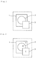
- Fig. 1 shows original figures of first through third image parts 1 through 3.
- the numerals '1', '2', and '3' represent image parts themselves as well as their overlap orders.
- the first image part 1 is a rectangle painted with yellow (Y) printing ink;
- the second image part 2 is a circle painted with magenta (M) printing ink;
- the third image part 3 is a rectangle printed with cyan (C) printing ink.
- 'Knockout' process gives preference to the second image part and ignores the first image part. Namely, the 'Knockout' process gives preference to a knockout or upper image part over a lower image part having a lower overlap order for all of Y, M, C, and K color plates.
- the third image part 3 is preferential over the first and the second image parts 1 and 2 having the lower overlap orders, and the densities of knocked-out portions of the first and the second image parts 1 and 2 are ignored.
- the second image part 2 is preferential over the first image part 1 having the lower overlap order, and the density of a knocked-out portion of the first image part 1 is ignored.
- the density of the first image part 1 is adopted for the Y color plate.
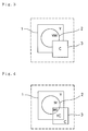
- 'Overprint' process prints the second image part over the first image part.
- the 'Overprint' process adopts the density of an overprint or upper image part preferential over a lower image part having a lower overlap order for a color plate having an effective density in the upper image part, while adopting the density of the lower image part for a color plate having no effective density (that is, zero density) in the upper image part.
- Image parts are defined by the densities corresponding to the respective color plates Y, M, C, and K.
- the color plate having an effective density in the image part specified as above implies a color plate having a non-zero density in the image part.
- the color plate having no effective density in the image part means a color plate having zero density in the image part.
- the expressions like effective density and no effective density have the above implications.
- the 'Overprint' attribute is allocated only to the second image part 2, this gives a printing result shown in Fig. 3.
- the density of the second image part 2 is adopted to be preferential over the first image part 1 having the lower overlap order for the M color plate having an effective density in the second image part 2.
- the second image part 2 however, has no effective density in the Y color plate, and the density of the first image part 1 having the lower overlap order is accordingly adopted for the Y color plate.
- the third image part 3 has the 'Knockout' attribute and is thus expressed only by the C color plate.
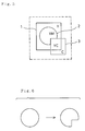
- the 'Overprint' attribute is allocated only to the third image part 3, this gives a printing result shown in Fig. 4.
- the density of the third image part 3 is adopted to be preferential over the first image part 1 and the second image part 2 having the lower overlap orders for the C color plate having an effective density in the third image part 3.
- the third image part 3 however, has no effective densities in the Y and M color plates, and the densities of the first image part 1 and the second image part 2 having the lower overlap orders are respectively adopted for the Y and M color plates.
- the relationship between the first image part 1 and the second image part 2 is defined by the 'Knockout' attribute allocated to the second image part 2.
- Allocation of the 'Knockout' and 'Overprint' attributes to the respective image parts allows an overlap of the image parts to be expressed in general prepress process.
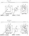
- This conventional method does not always succeed in expressing an overlap state of image parts appropriately. For example, it fails to express a printing state shown in Fig. 5, where the second image part 2 is affected by the density of the first image part 1, while the third image part 3 is affected not by the density of the second image part 2 but by the density of the first image part 1.
- Such a printing result can not be obtained by 'Knockout' and 'Overprint' techniques, since 'Knockout' excludes any effect of the lower image parts while 'Overprint' accepts any effect of the lower image parts.
- the conventional method can not selectively change the effect of lower image parts, thereby not giving such a printing result.
- Fig. 5 The example of Fig. 5 is often observed when a print is on soft packaging material like vinyl or cellophane.
- Soft packaging members composed of material like vinyl or cellophane with high transparency are widely used for wrapping and packaging food.
- Printing on such soft packaging material requires a pre-process of filling a printing area with white ink prior to printing inks of primary colors over the white background, in order to reproduce the same colors as print on standard white paper.
- white separation white ink
- image parts printed over the white separation are required to be constantly affected by white ink (this corresponds to an 'Underprint' attribute in the description of an embodiment below).
- the first image part 1 represents the white separation, it should be easily understood that the printing result of Fig. 5 is often required.
- the conventional method described above can not express the overlap state of image parts shown in Fig. 5 and is thus not applicable to soft packaging gravure process, where figures and characters are to be printed on soft packaging material.
- the printing state shown in Fig. 5 is obtained with only the 'Knockout' and 'Overprint' attributes by cutting a part of the circle of the second image part 2 as shown in Fig. 6.
- This requires time- and labor-consuming computer operations for checking overlap states of the respective image parts and deforming the shapes according to the requirements, thereby lowering the processing speed.
- the image part once processed to have a deformed shape can not be changed or modified easily like original image parts. This requires complicated operations even for simple correction of a figure.
- One object of the present invention is thus to effectively express an overlap state of image parts, which can conventionally be expressed only by deformation of the image parts, and thereby allow application to soft packaging gravure process.
- Another object of the invention is to increase the processing speed and reduce the time and labor required for 'correction'.
- the above and the other related objects are realized by a method of generating a plurality of color separation images of a color image including a plurality of image parts.
- the method comprises:
- the invention is also directed to an apparatus for generating a plurality of color separation images of a color image including a plurality of image parts.
- the apparatus comprises: a memory for storing image parts information representing the plurality of image parts, the image parts information representing density of each of the plurality of image parts for each of a plurality of color separations, overlap order information representing a set of orders of the plurality of image parts in overlapping the plurality of image parts, and attribute information representing a set of attributes of the plurality of image parts in overlapping the plurality of image parts; and control means for determining density of a color separation image for a subject color separation, including: judging means for judging from the overlap order information whether at least two overlapping image parts including a lower image part and an upper image part exist or not; and adopting means for, when the overlap order information indicates existence of the upper image part and the lower image part and when the lower image part has a predetermined attribute, adopting a density of the lower image part for a color separation image, irrespective of an attribute allocated to the upper image
- the invention is further directed to another apparatus for generating a plurality of color separation images of a color image including a plurality of image parts.
- the apparatus comprises: a memory for storing image parts information representing the plurality of image parts, the image parts information representing density of each of the plurality of image parts for each of a plurality of color separations, overlap order information representing a set of orders of the plurality of image parts in overlapping the plurality of image parts, and attribute information representing a set of attributes of the plurality of image parts in overlapping the plurality of image parts; and control means for determining density of a color separation image for a subject color separation, including: judging means for judging from the overlap order information whether at least two overlapping image parts including a lower image part and an upper image part exist or not; and adopting means for, when the overlap order information indicates existence of the upper age part and the lower image part and when the lower image part has a predetermined attribute, adopting the higher of densities of the upper image part and the lower image part for a color separation image, irrespective
- Fig. 9 is a block diagram schematically illustrating a processing system 10, which realizes a method of generating color separation images embodying the invention.
- the processing system 10 includes a CPU 12, a ROM (read only memory) 16, and a RAM (random access memory) 18, which are interconnected via a bus line 14.
- the bus line 14 is also connected to a keyboard 20 and a mouse 22 via an input interface 24, a color CRT 26 via a display controller 28, and a recorder 30 via a recorder interface 32 and a halftone generating circuit 34.
- Control programs 16a and control data 16b required for executing a variety of operations are previously stored in the ROM 16, whereas data including object information 18a and overlap information 18b required for executing the variety of operations are stored in the RAM 18.
- the object information 18a is a set of image data representing figures, characters, pictures, and other image parts (hereinafter referred to as objects).
- Image data corresponding to picture objects are obtained by optically reading an original image with a picture scanner (not shown); those corresponding to character objects are by inputting character cord with a word processor (not shown); and those for figure objects are by reading the original figure with a linework scanner (not shown).
- Different types of image data have different structures.
- Image data of a figure object include outline data representing the outline of the figure, positional data representing the position of the figure, and color data representing densities of four color plates, that is, yellow (Y), magenta (M), cyan (C), and black (K) plates, in an area inside the outline.
- the overlap information 18b defines an overlap state of a plurality of objects and has a table structure shown in Fig. 10.
- the table is a set of records corresponding to 'm' objects, where each record is an array of three elements.
- the three elements of record are a pointer Pm for specifying each object, an overlap order data Lm representing an overlap order of each object, and an attribute data Am representing an attribute or characteristic of the overlap.
- the pointer Pm shows an address where image data of each object is stored.
- the overlap order data Lm are integers of not less than 1, where the greater numeral denotes the upper position in overlap.
- the attribute data Am are numerals of 0 through 3, where 0, 1, 2, and 3 respectively represent 'Knockout', 'Underprint', 'Overprint', and 'Overprint + Underprint'.
- the overlap information 18b is obtained by processing operator's key inputs as described below.
- the RAM 18 also has three specific areas used for output operation of image data; that is, a primary area E0 and first and second auxiliary areas E1 and E2 for temporary use.
- Each area E0, E1, or E2 consists of areas of Y, M, C, and K plates and represents output condition of image data in bit map data structure.
- Each color pate of the respective areas E0, E1, and E2 has a depth of tone (for example, 8 bits). Actual application of these areas E0, E1, and E2 will be described later.
- the CPU 12 executes the programs previously stored in the ROM 16 to prepare a page image based on a plurality of objects stored as the object information 18a in the RAM 18 and output the page image to the recorder 30.
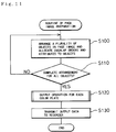
- Fig. 11 is a flowchart showing a routine of page image preparation executed by the CPU 12.
- the CPU 12 arranges a plurality of objects in a page image expressed as page data Dp and simultaneously gives overlap orders and attributes to the respective objects at step S100.
- the CPU 12 reads page data Dp corresponding to one page from a magnetic disk (not shown) or the like and displays a page image corresponding to the page data Dp on the color CRT 26 via the display controller 28.
- the operator interacts with the page image displayed on the screen of color CRT 26 and arranges a plurality of objects, which are stored in the RAM 18, in the page image with the keyboard 20 and the mouse 22.
- the CPU 12 allocates values to positional data of the respective objects in the object information 18a.
- the CPU 12 simultaneously gives overlap orders and attributes regarding the overlap to the respective objects to complete the overlap information 18b.
- step S110 it is determined whether all the objects previously stored in the RAM 18 have been arranged in the page image.
- step S110 the program returns to step S100 to repeat the process for the remaining objects.
- step S100 the program has affirmative answer at step S110 and goes to step S120.
- step S120 the CPU 12 executes output operation to obtain output data Dy, Dm, Dc, and Dk of the Y, M, C, and K color plates based on the object information 18a and the overlap information 18b generated at step S100.
- the process of output operation will be described later in detail.
- the program subsequently goes to step S130 at which the CPU 12 transmits the output data Dy, Dm, Dc, and Dk to the recorder interface 32.
- the program then goes to END to exit from the routine.
- the output operation executed at step S120 expands each object to bit map data based on the object information 18a, stores the bit map data into the output-operation areas E0 through E2 on the RAM 18 by referring to the overlap information 18b, and composes the output data Dy, Dm, Dc, and Dk of the Y, M, C, and K color plates from the bit map data of the respective objects.
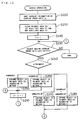
- Figs. 12 through 14 are flowcharts showing details of the output operation executed at step S120 of the page image preparation routine shown in Fig. 11.
- the CPU 12 When the program enters the routine of output operation, the CPU 12 first sorts the overlap information 18b by the overlap order data Lm at step S200. The CPU 12 then clears all the primary area E0, the first auxiliary area E1, and the second auxiliary area E2 assigned in the RAM 18 at step S210 and sets a variable 'n' to an initial value at step S220. The areas E1, E2, and E3 are cleared by initializing all pixels in these areas of the Y, M, C, and K color plates to zero.
- the CPU 12 reads the overlap information 18b stored in the RAM 18 to determine whether any object has overlap order data Lm equal to the value of the variable 'n'.
- the CPU 12 successively searches the table of overlap information 18b and, when finding the overlap order data Lm equal to the value of the variable 'n', determines that a target object exists.
- step S230 When the answer is negative at step S230, the program goes to END and exits from this routine.
- step S240 the CPU 12 determines the attribute of the target object: 'Knockout', 'Overprint', 'Underprint', or 'Overprint + Underprint'.
- the CPU 12 compares the attribute data Am of the target record, which has been determined to have the overlap order data Lm equal to the value of the variable 'n' at step S230, with the values '0' through '3'.
- step S240 the program goes to step S250 at which the CPU 12 expands the target object in the primary area E0 according to 'method 1', which is a method of determining the density by taking account of the attribute as described later.
- the CPU 12 first specifies a target object in the object information 18a, based on the pointer Pm of the target record, which has been determined to have the overlap order data Lm equal to the value of the variable 'n' at step S230.
- the CPU 12 reads information regarding the target object, generates bit map image data representing the target object, based on the information regarding the target object, and finally expands the image data of the target object in the primary area E0 according to the 'method 1'.
- step S240 When the attribute data Am of the target record is equal to one, that is, 'Overprint', at step S240, the program goes to step S260 at which the CPU 12 generates bit map image data representing a target object in the same manner as above and expands image data of the target object in the primary area E0 according to 'method 2', which is a method of determining the density by taking account of the attribute as described later.
- step S240 When the attribute data Am of the target record is equal to two, that is, 'Underprint', at step S240, the program goes to step S270 at which the CPU 12 generates bit map image data representing a target object in the same manner as above and expands image data of the target object in the primary area E0 according to 'method 3', which is a method of determining the density by taking account of the attribute as described later.
- step S240 When the attribute data Am of the target record is equal to three, that is, 'Overprint + Underprint', at step S240, the program goes to step S280 at which the CPU 12 generates bit map image data representing a target object in the same manner as above and expands image data of the target object in the primary area E0 according to 'method 4', which is a method of determining the density by taking account of the attribute as described later.
- the 'method 1' overwrites the target object having 'Knockout' attribute, where the density of the overwritten target object is preferential over the density of the lower object (previous state) for all the four color plates, Y, M, C, and K.
- the 'method 2' overwrites the target object having 'Overprint' attribute, where the density of the overwritten target object is preferential over the density of the lower object (previous state) for color plates having effective densities in the overwritten target object, while the density of the lower object is adopted for color plates having no effective densities.
- This rule is expressed as Equations (2) through (7) given below, where Iy2, Im2, Ic2, and Ik2 represent effective densities other than 0[%]:
- the 'method 3' overwrites the target object having 'Underprint' attribute, which corresponds to the 'method 1' for overwriting the target object having 'Knockout' attribute.
- the 'method 4' overwrites the target object having 'Overprint + Underprint' attribute, which corresponds to the 'method 2' for overwriting the target object having 'Overprint' attribute.
- step S290 the color density of the target object affects only the lower objects having lower overlap orders than 'n' while not affecting the upper objects. This allows subsequent objects to be processed successively.
- step S300 in the flowchart of Fig. 13, at which the CPU 12 reads the overlap information 18b stored in the RAM 18 to determine whether any object has overlap order data Lm equal to the value of the variable 'n+1'. In other words, the CPU 12 determines the presence or absence of an upper object having an upper overlap order by one than the object expanded in the primary area E0 and having the n-th overlap order.
- the program goes to END and exits from the routine.
- step S300 the program goes to step S310 at which the new target object is determined whether to have the 'Knockout' or 'Overprint' attribute or to have the 'Underprint' or 'Overprint + Underprint' attribute.
- the CPU 12 determines whether the attribute data Am of the target record, which has been determined to have the overlap order data Lm equal to the value of the variable 'n+1' at step S300, is equal to the value '0' or '1' or the value '2' or '3'.
- step S310 When the new target object is determined to have the 'Underprint' or 'Overprint + Underprint' attribute at step S310, the program returns to step S290 in the flowchart of Fig. 12 to repeat the subsequent process.
- the program goes to step S320 at which the CPU 12 clears the first auxiliary area E1, and to step S330 at which the CPU 12 reversely masks the first auxiliary area E1 with the object having the n-th overlap order.
- the CPU 12 copies the primary area E0 to the second auxiliary area E2 on the RAM 18 at step S340, and masks the second auxiliary area E2 with the object having the n-th overlap order at step S350.
- step S350 the program proceeds to step S360 at which it is determined whether the new target object specified at step S300 has the 'Knockout' attribute.
- step S360 the program proceeds to step S370 at which the CPU 12 expands the new target object having the (n+1)-th overlap order in the first auxiliary area E1 and the second auxiliary area E2 according to the 'method 1' for determining the density by taking account of the attribute.
- step S380 the CPU 12 expands the new target object having the (n+1)-th overlap order in the first auxiliary area E1 and the second auxiliary area E2 according to the 'method 2' for determining the density by taking account of the attribute.
- step S370 After execution of either step S370 or step S380, the program goes to step S390 at which the variable 'n' is incremented by one and then to step S400 in the flowchart of Fig. 14.
- the CPU 12 reads the overlap information 18b stored in the RAM 18 to determine whether any object has overlap order data Lm equal to the value of the variable 'n+1'. In other words, the CPU 12 determines the presence or absence of an upper object having an upper overlap order by two than the object expanded in the primary area E0 and having the n-th overlap order (since the variable 'n' has already been incremented by one at step S290).
- step S410 the CPU 12 determines whether the new target object has the 'Knockout' attribute, the 'Overprint' attribute, or the 'Underprint' or 'Overprint + Underprint' attribute. According to a concrete operation, the CPU 12 determines whether the attribute data Am of the target record, which has been determined to have the overlap order data Lm equal to the value of the variable 'n+1' at step S400, is equal to the value '0', the value '1', or the value '2' or '3'.
- step S410 When the target object is determined to have the 'Knockout' attribute at step S410, the program proceeds to step S420 at which the CPU 12 expands the target object in the first auxiliary area E1 and the second auxiliary area E2 according to the 'method 1' described above.
- step S410 When the target object is determined to have the 'Overprint' attribute at step S410, the program goes to step S430 at which the CPU 12 expands the target object in the first auxiliary area E1 and the second auxiliary area E2 according to the 'method 2' described above. After execution of either step S420 or step S430, the program goes to step S440 at which the variable 'n' is incremented by one, and then returns to step S400 to repeat the subsequent process.
- the CPU 12 When the target object is determined to have the 'Underprint' or 'Overprint + Underprint' attribute at step S410, the CPU 12 combines the first auxiliary area E1 with the primary area E0 according to the 'method 2' at step S450, and combines the second auxiliary area E2 with the primary area E0 according to the 'method 1' at step S460. The program then returns to step S290 in the flowchart of Fig. 12 to repeat the subsequent process.
- the CPU 12 When the answer is negative at step S400, the CPU 12 combines the first auxiliary area E1 with the primary area E0 according to the 'method 2' at step S470, and combines the second auxiliary area E2 with the primary area E0 according to the 'method 1' at step S480, in the same manner as the processing at steps S450 and S460.
- the program then goes to END and exits from the routine.
- steps S230 through S280 expands the n-th object having the n-th overlap order in the primary area E0 on the RAM 18.
- steps S230 through S280 successively increments the overlap order by one and expands the overlapping objects in the primary area E0.
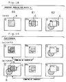
- the output operation thus constituted expands each object in the primary area E0, the first auxiliary area E1, or the second auxiliary area E2 on the RAM 18. This expansion process is described with a sample shown in Table 1.
- Table 1 Objects Overlap orders Attributes Object A 1 2 [Underprint] Object B 2 0 [Knockout] Object C 3 0 [Knockout]
- the pre-processing step S210 in the flowchart of Fig. 12 clears all the bits in the primary area E0, the first auxiliary area E1, and the second auxiliary area E2 to zero as shown in Fig. 15.
- the processing at steps S230, S240, and S270 expands an object A having the overlap order '1' is expanded in the primary area E0 according to the 'method 3' as shown in Fig. 16(a).
- hatched areas represent the density data of the object A.
- the value '0' remains in the residual bits of the primary area E0 other than the object A as well as in all the bits of the first auxiliary area E1 and the second auxiliary area E2.
- step S340 copies the primary area E0 to the second auxiliary area E2 as shown in Fig. 16(c).
- step S350 allocates the value FFh to the area of the object A in the second auxiliary area E2 while assigning the value '0' to the residual area as shown in Fig. 16(d).
- step S370 allocates the density data of the object B to the area of the object B not having the value FFh but having the value '0' in the first auxiliary area E1 and the second auxiliary area E2 as shown in Fig. 17.
- step S420 allocates the density data of the object C to the area of the object C not having the value FFh but having the value '0' in the first auxiliary area E1 and the second auxiliary area E2 as shown in Fig. 18.
- step S470 combines the first auxiliary area E1 with the primary area E0 according to the overprint process as shown in Fig. 19(a). Namely, the image of the first auxiliary area E1 is laid upon and combined with the primary area E0 where the density data of the object A is expanded.
- Step S480 then combines the second auxiliary area E2 with the primary area E0 according to the knockout process as shown in Fig. 19(b). Namely, the image of the second auxiliary area E2 except the area of the value FFh is combined with the primary area E0 where the density data of the object A is expanded.
- Data of the page image thus generated in the primary area E0 are transmitted as output data Dy, Dm, Dc, and Dk of the respective color plates, Y, M, C, and K, via the recorder interface 32 to the halftone generating circuit 34.
- the halftone generating circuit 34 converts the output data Dy, Dm, Dc, and Dk to halftone signals.
- the recorder 30 receives the halftone signals and records color separation images corresponding to the four color plates on a photosensitive film.
- the objects A through C are expressed as monochromatic figure information respectively having uniform density data with respect to the Y, M, C printing inks.
- the image shown in Fig. 20 is accordingly recorded by the recorder 30.
- the overlap of the object B with the object A is affected by the density of the object A
- the overlap of the object B and the object C with the object A is affected not by the density of the object B but by the density of the object A. This corresponds to the state shown in Fig. 5.
- the processing system 10 of the embodiment effectively expresses an overlap state of objects, which can conventionally be expressed only by deformation of the objects.
- the processing system 10 of the embodiment is accordingly applicable to soft packaging gravure process. No deformation of the objects increases the processing speed and reduces the time and labor required for 'correction'.
- the 'Overprint + Underprint' attribute having both the functions of overprint and underprint is set as one of available overlap attributes. This helps the operator easily make and edit a page image.
- the 'method 2' of determining the density by taking account of the attribute adopts the density of an overwritten object preferential over the density of a lower object for color plates having effective densities in the overwritten object.
- the 'method 2' may adopt the higher of the densities of an overwritten object and a lower object for color plates having effective densities in the overwritten object.
Landscapes
- Engineering & Computer Science (AREA)
- Multimedia (AREA)
- Signal Processing (AREA)
- Color, Gradation (AREA)
- Preparing Plates And Mask In Photomechanical Process (AREA)
- Image Processing (AREA)
- Editing Of Facsimile Originals (AREA)
- Color Image Communication Systems (AREA)
- Processing Or Creating Images (AREA)
Applications Claiming Priority (2)
| Application Number | Priority Date | Filing Date | Title |
|---|---|---|---|
| JP259310/94 | 1994-09-29 | ||
| JP25931094A JP2898889B2 (ja) | 1994-09-29 | 1994-09-29 | 製版処理方法 |
Publications (2)
| Publication Number | Publication Date |
|---|---|
| EP0705024A2 true EP0705024A2 (fr) | 1996-04-03 |
| EP0705024A3 EP0705024A3 (fr) | 1997-01-15 |
Family
ID=17332305
Family Applications (1)
| Application Number | Title | Priority Date | Filing Date |
|---|---|---|---|
| EP95115092A Withdrawn EP0705024A3 (fr) | 1994-09-29 | 1995-09-25 | Procédé et appareil pour la génération d'images de séparation en couleurs |
Country Status (2)
| Country | Link |
|---|---|
| EP (1) | EP0705024A3 (fr) |
| JP (1) | JP2898889B2 (fr) |
Cited By (5)
| Publication number | Priority date | Publication date | Assignee | Title |
|---|---|---|---|---|
| DE10103432A1 (de) * | 2000-01-28 | 2001-09-06 | Acer Comm & Multimedia Inc | Bildbearbeitungsverfahren |
| US7995238B2 (en) | 2004-01-30 | 2011-08-09 | Fuji Xerox Co., Ltd. | Image processing that can use both process and spot color plates |
| EP2267593A3 (fr) * | 2009-06-24 | 2013-01-23 | Konica Minolta Systems Laboratory, Inc | Détection de couleurs améliorée pendant l'analyse de documents avant impression |
| US8947741B2 (en) | 2012-09-18 | 2015-02-03 | Fuji Xerox Co., Ltd. | Converting color values of print data into color space of print apparatus and producing new object from overlap portion of plural objects to superimpose thereon with knock-out method |
| EP4035898A4 (fr) * | 2019-10-10 | 2023-09-27 | Toyo Seikan Co., Ltd. | Procédé de fabrication de plaques, système de fabrication de plaques et corps de boîte |
Families Citing this family (16)
| Publication number | Priority date | Publication date | Assignee | Title |
|---|---|---|---|---|
| DE19623327A1 (de) * | 1996-06-12 | 1997-12-18 | Hell Ag Linotype | Verfahren zur Bearbeitung von Objekten auf Druckseiten |
| US7151546B1 (en) * | 1999-12-22 | 2006-12-19 | Adobe Systems Incorporated | Restricting scope of blending modes in 2-D compositing using isolated groups |
| JP4165039B2 (ja) * | 2001-06-20 | 2008-10-15 | 富士ゼロックス株式会社 | 画像処理装置 |
| JP4024744B2 (ja) * | 2003-11-06 | 2007-12-19 | 大日本スクリーン製造株式会社 | トラッピング方法、トラッピング装置、トラッピングプログラム、および印刷システム |
| JP4142614B2 (ja) * | 2003-11-10 | 2008-09-03 | 大日本スクリーン製造株式会社 | トラッピング方法、トラッピングプログラム、トラッピング装置および印刷システム |
| JP4682628B2 (ja) * | 2004-01-30 | 2011-05-11 | 富士ゼロックス株式会社 | 画像処理装置、方法、及びプログラム |
| JP2006108967A (ja) * | 2004-10-04 | 2006-04-20 | Dainippon Printing Co Ltd | オーバープリント処理を施した製版データ作成方法、装置 |
| JP4169053B2 (ja) * | 2006-07-05 | 2008-10-22 | ブラザー工業株式会社 | 画像処理装置及び画像処理方法 |
| JP2008022201A (ja) * | 2006-07-12 | 2008-01-31 | Fuji Xerox Co Ltd | 画像処理装置及びプログラム |
| JP4535141B2 (ja) * | 2008-02-12 | 2010-09-01 | 富士ゼロックス株式会社 | 画像処理装置 |
| JP5434555B2 (ja) * | 2009-12-14 | 2014-03-05 | 富士ゼロックス株式会社 | 画像情報処理装置及びプログラム |
| JP5732935B2 (ja) * | 2011-03-15 | 2015-06-10 | 株式会社リコー | 情報処理装置と印刷制御プログラムとコンピュータ読み取り可能な記録媒体 |
| JP6874808B2 (ja) * | 2019-10-10 | 2021-05-19 | 東洋製罐株式会社 | 製版方法、製版システム及び缶体 |
| JP6891939B2 (ja) * | 2019-10-10 | 2021-06-18 | 東洋製罐株式会社 | 製版方法、製版システム及び缶体 |
| JP7163445B2 (ja) * | 2021-04-07 | 2022-10-31 | 東洋製罐株式会社 | 製版方法、製版システム及び缶体 |
| JP7158525B1 (ja) * | 2021-04-07 | 2022-10-21 | 東洋製罐株式会社 | 製版方法、製版システム及び缶体 |
Citations (1)
| Publication number | Priority date | Publication date | Assignee | Title |
|---|---|---|---|---|
| JPH06259310A (ja) | 1993-03-03 | 1994-09-16 | Tokyo Electric Co Ltd | ファイル制御装置 |
Family Cites Families (3)
| Publication number | Priority date | Publication date | Assignee | Title |
|---|---|---|---|---|
| JPS6049339A (ja) * | 1983-08-30 | 1985-03-18 | Dainippon Screen Mfg Co Ltd | 複製画像の編集装置 |
| US5113251A (en) * | 1989-02-23 | 1992-05-12 | Fuji Xerox Co. | Editing control system and area editing system for image processing equipment |
| EP0508123A1 (fr) * | 1991-03-09 | 1992-10-14 | Mita Industrial Co., Ltd. | Appareil de traitement d'image |
-
1994
- 1994-09-29 JP JP25931094A patent/JP2898889B2/ja not_active Expired - Fee Related
-
1995
- 1995-09-25 EP EP95115092A patent/EP0705024A3/fr not_active Withdrawn
Patent Citations (1)
| Publication number | Priority date | Publication date | Assignee | Title |
|---|---|---|---|---|
| JPH06259310A (ja) | 1993-03-03 | 1994-09-16 | Tokyo Electric Co Ltd | ファイル制御装置 |
Cited By (7)
| Publication number | Priority date | Publication date | Assignee | Title |
|---|---|---|---|---|
| DE10103432A1 (de) * | 2000-01-28 | 2001-09-06 | Acer Comm & Multimedia Inc | Bildbearbeitungsverfahren |
| US7995238B2 (en) | 2004-01-30 | 2011-08-09 | Fuji Xerox Co., Ltd. | Image processing that can use both process and spot color plates |
| EP2267593A3 (fr) * | 2009-06-24 | 2013-01-23 | Konica Minolta Systems Laboratory, Inc | Détection de couleurs améliorée pendant l'analyse de documents avant impression |
| US8947741B2 (en) | 2012-09-18 | 2015-02-03 | Fuji Xerox Co., Ltd. | Converting color values of print data into color space of print apparatus and producing new object from overlap portion of plural objects to superimpose thereon with knock-out method |
| AU2013201186B2 (en) * | 2012-09-18 | 2015-07-09 | Fujifilm Business Innovation Corp. | Image processing apparatus and program |
| EP4035898A4 (fr) * | 2019-10-10 | 2023-09-27 | Toyo Seikan Co., Ltd. | Procédé de fabrication de plaques, système de fabrication de plaques et corps de boîte |
| US12076975B2 (en) | 2019-10-10 | 2024-09-03 | Toyo Seikan Co., Ltd. | Plate-making method, plate-making system and can body |
Also Published As
| Publication number | Publication date |
|---|---|
| JP2898889B2 (ja) | 1999-06-02 |
| EP0705024A3 (fr) | 1997-01-15 |
| JPH08102845A (ja) | 1996-04-16 |
Similar Documents
| Publication | Publication Date | Title |
|---|---|---|
| EP0705024A2 (fr) | Procédé et appareil pour la génération d'images de séparation en couleurs | |
| US5204918A (en) | Method of and apparatus for correcting contour of image | |
| US5513300A (en) | Method and apparatus for producing overlapping image area | |
| US5610732A (en) | Image processing apparatus having unevenly gamut dividing color-converting function | |
| JPH0428191B2 (fr) | ||
| JPH0231910B2 (fr) | ||
| EP0484890A2 (fr) | Procédé et appareil d'obtention de zones d'image chevauchantes | |
| US5777758A (en) | Image processing apparatus and method for expanding color images based on block pixel and edge detection | |
| US5142355A (en) | Edit control system for use in an image processing apparatus | |
| US6259536B1 (en) | Color printing yielding a background dependent black image (i.e. intelligent black) | |
| US20040070777A1 (en) | Image processing method and image processing apparatus | |
| US7995238B2 (en) | Image processing that can use both process and spot color plates | |
| US6088124A (en) | Color image processing apparatus and method | |
| US5915075A (en) | Image processing apparatus for converting input color chart data into color data for an output device | |
| EP0782097B1 (fr) | Méthode et système pour l'impression digitale multicolore | |
| US5481662A (en) | Method of and apparatus for modifying base separation figure | |
| US5225901A (en) | Apparatus and method for converting and displaying r, g, and b signals from a prepress scanner | |
| JP2633567B2 (ja) | 画像処理方法 | |
| EP0418868B1 (fr) | Système de traitement d'image | |
| JP3636891B2 (ja) | カラー画像出力方法 | |
| JP3311101B2 (ja) | 画像処理装置 | |
| JP3199810B2 (ja) | 画像処理方法及びその装置 | |
| JPH0654179A (ja) | 画像処理装置 | |
| JP2921850B2 (ja) | 画像処理装置 | |
| JP3039657B2 (ja) | 画像処理装置 |
Legal Events
| Date | Code | Title | Description |
|---|---|---|---|
| PUAI | Public reference made under article 153(3) epc to a published international application that has entered the european phase |
Free format text: ORIGINAL CODE: 0009012 |
|
| AK | Designated contracting states |
Kind code of ref document: A2 Designated state(s): DE FR GB |
|
| K1C1 | Correction of patent application (title page) published |
Effective date: 19960403 |
|
| PUAL | Search report despatched |
Free format text: ORIGINAL CODE: 0009013 |
|
| AK | Designated contracting states |
Kind code of ref document: A3 Designated state(s): DE FR GB |
|
| 17P | Request for examination filed |
Effective date: 19970415 |
|
| 17Q | First examination report despatched |
Effective date: 19981117 |
|
| STAA | Information on the status of an ep patent application or granted ep patent |
Free format text: STATUS: THE APPLICATION IS DEEMED TO BE WITHDRAWN |
|
| 18D | Application deemed to be withdrawn |
Effective date: 19990330 |