EP0705146B1 - Zerstäuber - Google Patents
Zerstäuber Download PDFInfo
- Publication number
- EP0705146B1 EP0705146B1 EP94918477A EP94918477A EP0705146B1 EP 0705146 B1 EP0705146 B1 EP 0705146B1 EP 94918477 A EP94918477 A EP 94918477A EP 94918477 A EP94918477 A EP 94918477A EP 0705146 B1 EP0705146 B1 EP 0705146B1
- Authority
- EP
- European Patent Office
- Prior art keywords
- diaphragm
- gas
- flow
- chamber
- aperture
- Prior art date
- Legal status (The legal status is an assumption and is not a legal conclusion. Google has not performed a legal analysis and makes no representation as to the accuracy of the status listed.)
- Expired - Lifetime
Links
- 239000003570 air Substances 0.000 claims description 67
- 239000007788 liquid Substances 0.000 claims description 60
- 239000000463 material Substances 0.000 claims description 37
- 238000000034 method Methods 0.000 claims description 22
- 238000006073 displacement reaction Methods 0.000 claims description 14
- 230000007246 mechanism Effects 0.000 claims description 13
- 230000004044 response Effects 0.000 claims description 12
- 239000000843 powder Substances 0.000 claims description 9
- 230000009969 flowable effect Effects 0.000 claims description 5
- 239000012080 ambient air Substances 0.000 claims description 4
- 238000011144 upstream manufacturing Methods 0.000 claims description 4
- 239000007787 solid Substances 0.000 claims description 3
- 238000004891 communication Methods 0.000 claims description 2
- 208000028659 discharge Diseases 0.000 claims 2
- 238000007599 discharging Methods 0.000 claims 2
- 238000000889 atomisation Methods 0.000 description 10
- 230000000694 effects Effects 0.000 description 7
- 230000009471 action Effects 0.000 description 5
- 230000008901 benefit Effects 0.000 description 5
- 239000000446 fuel Substances 0.000 description 4
- 238000002664 inhalation therapy Methods 0.000 description 4
- 239000002245 particle Substances 0.000 description 4
- 230000010355 oscillation Effects 0.000 description 3
- CURLTUGMZLYLDI-UHFFFAOYSA-N Carbon dioxide Chemical compound O=C=O CURLTUGMZLYLDI-UHFFFAOYSA-N 0.000 description 2
- 230000015572 biosynthetic process Effects 0.000 description 2
- 238000013016 damping Methods 0.000 description 2
- 238000010586 diagram Methods 0.000 description 2
- 239000012530 fluid Substances 0.000 description 2
- 239000008187 granular material Substances 0.000 description 2
- 239000003595 mist Substances 0.000 description 2
- 230000004048 modification Effects 0.000 description 2
- 238000012986 modification Methods 0.000 description 2
- 239000011236 particulate material Substances 0.000 description 2
- 230000037452 priming Effects 0.000 description 2
- 239000011343 solid material Substances 0.000 description 2
- XLYOFNOQVPJJNP-UHFFFAOYSA-N water Substances O XLYOFNOQVPJJNP-UHFFFAOYSA-N 0.000 description 2
- 238000009825 accumulation Methods 0.000 description 1
- 229910002092 carbon dioxide Inorganic materials 0.000 description 1
- 239000001569 carbon dioxide Substances 0.000 description 1
- 238000002485 combustion reaction Methods 0.000 description 1
- 230000003247 decreasing effect Effects 0.000 description 1
- 230000001419 dependent effect Effects 0.000 description 1
- 230000000994 depressogenic effect Effects 0.000 description 1
- 230000001627 detrimental effect Effects 0.000 description 1
- 239000006185 dispersion Substances 0.000 description 1
- 239000011888 foil Substances 0.000 description 1
- 230000003993 interaction Effects 0.000 description 1
- 210000003041 ligament Anatomy 0.000 description 1
- 239000011344 liquid material Substances 0.000 description 1
- 239000012263 liquid product Substances 0.000 description 1
- 229940126601 medicinal product Drugs 0.000 description 1
- 239000012528 membrane Substances 0.000 description 1
- 239000002184 metal Substances 0.000 description 1
- 229920003023 plastic Polymers 0.000 description 1
- 239000004033 plastic Substances 0.000 description 1
- 229920003223 poly(pyromellitimide-1,4-diphenyl ether) Polymers 0.000 description 1
- 229920006267 polyester film Polymers 0.000 description 1
- 230000008569 process Effects 0.000 description 1
- 239000000047 product Substances 0.000 description 1
- 238000010926 purge Methods 0.000 description 1
- 230000009467 reduction Effects 0.000 description 1
- 230000002040 relaxant effect Effects 0.000 description 1
- 238000005507 spraying Methods 0.000 description 1
- 239000000725 suspension Substances 0.000 description 1
- 230000002459 sustained effect Effects 0.000 description 1
- 238000002604 ultrasonography Methods 0.000 description 1
Images



Classifications
-
- A—HUMAN NECESSITIES
- A61—MEDICAL OR VETERINARY SCIENCE; HYGIENE
- A61M—DEVICES FOR INTRODUCING MEDIA INTO, OR ONTO, THE BODY; DEVICES FOR TRANSDUCING BODY MEDIA OR FOR TAKING MEDIA FROM THE BODY; DEVICES FOR PRODUCING OR ENDING SLEEP OR STUPOR
- A61M15/00—Inhalators
- A61M15/0065—Inhalators with dosage or measuring devices
-
- A—HUMAN NECESSITIES
- A61—MEDICAL OR VETERINARY SCIENCE; HYGIENE
- A61M—DEVICES FOR INTRODUCING MEDIA INTO, OR ONTO, THE BODY; DEVICES FOR TRANSDUCING BODY MEDIA OR FOR TAKING MEDIA FROM THE BODY; DEVICES FOR PRODUCING OR ENDING SLEEP OR STUPOR
- A61M15/00—Inhalators
- A61M15/0001—Details of inhalators; Constructional features thereof
- A61M15/0005—Details of inhalators; Constructional features thereof with means for agitating the medicament
-
- B—PERFORMING OPERATIONS; TRANSPORTING
- B05—SPRAYING OR ATOMISING IN GENERAL; APPLYING FLUENT MATERIALS TO SURFACES, IN GENERAL
- B05B—SPRAYING APPARATUS; ATOMISING APPARATUS; NOZZLES
- B05B17/00—Apparatus for spraying or atomising liquids or other fluent materials, not covered by the preceding groups
- B05B17/04—Apparatus for spraying or atomising liquids or other fluent materials, not covered by the preceding groups operating with special methods
- B05B17/06—Apparatus for spraying or atomising liquids or other fluent materials, not covered by the preceding groups operating with special methods using ultrasonic or other kinds of vibrations
- B05B17/0692—Apparatus for spraying or atomising liquids or other fluent materials, not covered by the preceding groups operating with special methods using ultrasonic or other kinds of vibrations generated by a fluid
Definitions
- This invention relates to a method of dispensing a flowable material in which a quantity of the material is entrained in a flow of gas and is atomised.
- a particular use for such atomisation is in the dispensing of medicinal products where liquid or particulate material should preferably be finely atomised prior to inhalation, it being a known characteristic of inhalation therapy that its effectiveness is critically dependent upon the material being finely atomised in a controlled manner.
- USSR Patent specification 825176 describes a device for spraying or atomising liquids or other fluids using ultrasound oscillations. Compressed gas is directed through a central tube onto a membrane which this causes to distort and oscillate. The fluid to be atomised is fed down a coaxial tube around the outside of the gas tube to the surface of the diaphragm in the form of a film. The gas disperses the film peripherally which is atomised on contact with the diaphragm.
- a method of dispensing a flowable material comprising the steps of supplying pressurised gas to a nozzle such that a flow of gas is discharged through an aperture defined between a lip of the nozzle and a diaphragm, introducing the material into the flow of gas such that material is entrained in the flow, and vibrating the diaphragm so as to atomise the material, the diaphragm constituting a wall of a chamber communicating with the aperture, the diaphragm being deformable in response to excess gas pressure in the chamber from a rest position to a displaced position in which the aperture is opened to receive the flow passing between the lip and the diaphragm, the pressurised gas being supplied via the chamber such that the diaphragm is deformed into the displaced position and the diaphragm being peripherally clamped such that it is maintained under tension in the displaced position whereby the diaphragm is vibrated by the flow of gas, characterised in that the diaphragm
- An advantage of this arrangement is that vibration of the diaphragm is excited and energised by the flow of gas without requiring any additional energy source to provide atomising vibration.
- the method includes the step of applying a tensioning force to the diaphragm such that it is maintained under tension in both the rest position and the displaced position.
- the diaphragm should be held in tension in this way if the contact with the lip is minimal or non-existent.
- ambient air may be admitted to the outlet via an opening defined in the central portion of the diaphragm.
- the vibrational characteristics of the diaphragm may be modified by the addition of a mass connected to the diaphragm.
- the supply of gas may be provided by an air pump providing compressed air to an accumulating reservoir to be subsequently released by action of a trigger.
- a pressurised container containing pressurised gas may be connected via a metering valve to the chamber for the release of a pulse of gas in response to actuation of the trigger.
- a continuously operating supply of gas may be connected to the chamber.
- apparatus for dispensing a flowable material comprising a nozzle, a gas supply for supplying pressurised gas to the nozzle such that a flow of gas is discharged in use through an aperture defined between a lip of the nozzle and a vibratable diaphragm, and dispensing means for introducing a quantity of the material into the flow whereby in use the material is entrained in the flow and atomised by the diaphragm
- the apparatus comprises a housing defining a chamber connected to the gas supply and communicating with an outlet defined by the nozzle via the aperture, the diaphragm constituting a wall of the chamber and being deformable in response to excess pressure in the chamber from a rest position to a displaced position in which the aperture is opened, and further comprising clamp means peripherally clamping the diaphragm such that the diaphragm is maintained under tension when deformed into the displaced position whereby the diaphragm is vibratable by the flow if gas
- Material in the form of a liquid may be dispensed by means of a displacement pump operable to dispense a metered volume of liquid.
- the dispensing means comprises a cylinder for receiving a quantity of liquid to be dispensed, a piston slidable in the cylinder to dispense liquid therefrom and an indexing mechanism operable to facilitate movement of the piston through predetermined incremental displacements at respective actuations of a trigger mechanism for the gas supply.
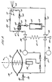
- a nozzle 1 defines an outlet 2 which is conically divergent in a direction of flow indicated by arrow A.
- the nozzle 1 terminates in an annular lip 3 defining a circular mouth 4 of the outlet 2.
- the nozzle 1 has a cylindrical outer surface 5 which is received in an annular housing 6, the surface 5 having a recessed portion 7 adjacent the lip 3 such that an annular chamber 8 is defined between the housing 6 and the recessed portion 7.
- a diaphragm 9 is clamped between the housing 6 and an annular clamp portion 10 and in its relaxed state as shown in Figure 1 traverses the mouth 4 in contact with the lip 3. In this rest position an outer portion 11 of the diaphragm constitutes an annular wall of the chamber 8. In this closed position the chamber 8 is isolated from the outlet 2.
- a gas inlet duct 12 extends radially through the housing 6 into communication with the chamber 8 and similarly a separate liquid inlet duct 13 communicates with the chamber 8 at a location circumferentially spaced from the gas inlet duct 12.
- Figure 2 shows the external appearance of a dispensing apparatus 20 incorporating the nozzle 1 within a mouth piece 21 defining an airway 22 through which in use a user inhales.
- the apparatus 20 is also provided with an air inlet opening (not shown) allowing air to be drawn into the airway 22 in a manner such that gas emerging from the nozzle 1 will be entrained in the inhaled air flow during inhalation.
- FIG. 3 shows a diaphragm pump 30 of a type which is operated by cam action deriving axial reciprocation of a pump diaphragm 31 from manual rotation of a pump actuator 23 as indicated in Figure 2.
- the pump 30 is connected to an air intake 32 via a one way valve 33 and delivers at each cycle of actuation a low pressure impulse of compressed air to a secondary compressor 34.
- the secondary compressor 34 is operated by movement of the actuator 23 180 o out of phase with the diaphragm pump 30 so as to provide a pressure boosted impulse of compressed air to a high pressure reservoir 35 which when charged contains air at about 5 bar.
- the diaphragm pump 30 is also connected to a low pressure reservoir 36 via one way valve 37, air pressure of about 1.5 bar being held in the low pressure reservoir 36 when charged.
- the diaphragm pump 30 includes a moulded face cam (not shown) which achieves during a single rotation of the actuator 23 a sequence of 4 axial cycles of the diaphragm to achieve the respective charged pressures referred to above.
- the high pressure reservoir 35 is connected via a first valve 38 to a passageway 39 communicating with the chamber 8.
- the passageway 39 includes a flow restrictor 40 and communicates with a branch passageway 41 to which it is connected upstream of the flow restrictor.
- the branch passageway 41 communicates with a displacement pump 42 which is arranged to displace a metered volume of liquid from a metering chamber 43 in response to pressurised gas being received through the branch passageway.
- the liquid inlet duct 13 communicates with the metering chamber 43 via a one way valve 44 and the metering chamber 43 is supplied with liquid from a liquid reservoir 45 via a further one way valve 46.
- the displacement pump 42 has a first piston 47 which is moveable in response to pressurised gas received through the branch passageway 41 to move a second piston 48 arranged to expel liquid from the metering chamber 43.
- the first and second pistons 47 and 48 are spring loaded into a return position such that return travel of the second piston draws liquid into the metering chamber from the liquid reservoir 45.
- the liquid reservoir 45 is partitioned by a flexible bag 49 containing the liquid to be dispensed.
- a second valve 50 is operatively connected to the first valve 38 by a trigger mechanism 51. Compressed air is supplied via the second valve 50 from the low pressure reservoir 36 to the liquid reservoir 45 so as to externally pressurise the flexible bag 49. The liquid contents are thereby pressurised and this aids the transfer of liquid into the metering chamber 43.
- the output of the second valve 50 is also connected by a further flow restrictor 52 to the outlet 2 of nozzle 1 via a low pressure air port 53 (not shown in Figure 1).
- a trigger 54 is provided as part of the trigger mechanism 51 for operating the first and second valves 38 and 50 and is located on the apparatus 20 adjacent the mouth piece 21 as shown in Figure 2.
- the trigger mechanism 51 is arranged to incorporate a spring mechanism operable such that actuation of the trigger 54 releases the second valve 50 and subsequently releases the first valve 38 thereby ensuring that the metering chamber 43 is filled with liquid and the pistons 47 and 48 are primed prior to release of the first valve 38.
- the user manually rotates the actuator 23 through 360 o thereby achieving pressurisation of both the high pressure reservoir 35 and the low pressure reservoir 36, this pressurisation being achieved as described above by a multi stage sequence in which the pump diaphragm 31 and secondary compressor 34 are repeatedly cycled.
- the user presents the mouth piece 21 ready for inhalation through the airway 22 and manually depresses the trigger 54.
- the second valve 50 opens thereby externally pressurising the flexible bag 49 and charging the metering chamber 43 with liquid.
- the first valve 38 then opens and high pressure air delivered via the branch passageway 41 actuates the displacement pump 42 to deliver a metered dose of liquid into the chamber 8.
- Figure 6 illustrates graphically the displacement of the diaphragm 9 away from the lip 3 as a function of time in response to a pulsed flow of gas being delivered to the chamber 8.
- the diaphragm 9 initially moves rapidly to its fully displaced position in response to an impulse of gas received within the chamber 8, the displacement of the diaphragm then progressively relaxing with decreasing gas pressure towards its rest position in which the aperture reduces to zero.
- a high frequency vibration of the diaphragm is superimposed on this displacement, the vibration being excited and energised by the flow of gas in a similar manner to that which is achieved in a conventional air horn such as those used in motor vehicles.
- Liquid entrained in the flow of gas has been observed to exit the aperture between the lip 3 and the diaphragm 9 as a wall jet with an initial velocity which is directed radially inwardly, the jet then forming extended ligaments which break up into droplets.
- the effect of the vibration present in the diaphragm 9 has been observed to be a marked reduction in the size of the droplets which are ultimately entrained in the air exiting from the outlet 2.
- the precise mechanism by which the vibration of the diaphragm 9 achieves this enhanced atomisation is believed to involve impact between the diaphragm and droplets and the effects of air currents created by the movement of the diaphragm.
- a finely atomised mist of liquid is thereby produced in the airway 22 and is inhaled via mouth piece 21.
- the flow velocity of the inhaled air is boosted by a secondary flow of air received via low pressure air port 53.
- the oscillation of the diaphragm continues until the available air pressure is no longer sufficient to unseat the diaphragm, the time constant of the oscillation being much smaller than the time taken for the gas pressure to fully depleat.
- a diaphragm having an exposed face of 8.5 mm diameter and cooperating with a lip of 6 mm diameter was found to operate satisfactorily when energised with an impulse of compressed air from a reservoir of 10 cc volume with an initial pressure of 5 bar.
- the diaphragm was found to oscillate at frequencies extending through the audible and into the ultrasonic range.
- the duration of the air impulse was of the order of 1 second. It was found that a liquid could be atomised in such an arrangement such that 90% of droplets were of less than 20 microns diameter, 60% were less than 10 microns diameter and 30% below 5 microns.
- Dispersion of the particulate solid material in this arrangement is believed to be primarily as a result of impact between the diaphragm and the material, the material then being dispersed into a fine powder which becomes entrained in the gas flow.
- Droplets of liquid may similarly be dispersed and atomised by introducing the liquid so as to rest upon the diaphragm.
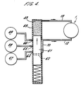
- the modified apparatus 60 of Figure 4 has a nozzle 1 of the type shown in Figure 1 receiving compressed air via a gas inlet duct 12 and a supply of liquid via a liquid inlet duct 13.
- a metering chamber 43 containing liquid receives a cylindrical piston 61 operable to displace the liquid and which includes a diametrically extending bore 62 allowing the piston 61 to also act as a shuttle valve for the release of compressed air.
- the piston 61 is slidable in a cylinder 63 having axially spaced air inlet ports 64, 65 and 66 connected to respective first, second and third high pressure air reservoirs 67, 68 and 69. Movement of the piston 61 along the cylinder 63 brings the bore 62 sequentially into registration with the first, second and third air inlet ports 64, 65 and 66 thereby constituting a valve means 61, 62, 63 allowing the compressed air to be conducted via an outlet port 70 into the gas inlet duct 12.
- valve means 61, 62, 63 may be incorporated into the apparatus of preceding Figures in order to deliver sequentially three separate impulses of compressed air during the discharge of liquid from the chamber 43. This modification takes account of the tendency for the liquid discharge to take longer to complete than the duration of an impulse of compressed air released from the high pressure reservoir.
- Figure 5 consists of a nozzle 1 defining an outlet 2 and an annular lip 3 defining a circular mouth 4 of the outlet.
- the nozzle 1 is received in an annular housing 6 and an annular chamber 8 is defined between the housing and a recessed portion 7 of the outer surface 5 of the nozzle 1.
- the diaphragm assembly 71 comprises a modified diaphragm 72 having a central opening 73 through which ambiant air may be drawn so as to flow through the outlet 2.
- the diameter of the opening 73 is less than that of the internal diameter of the lip 3 so that the presence of the opening does not affect the operational relationship between the lip and the diaphragm 72.
- a disc 74 is slidably received within the housing 6 immediately upstream of the diaphragm 72 and includes an axially projecting cylindrical projection 75 which is bonded to the diaphragm 72 peripherally of the opening 73.
- the cylindrical projection 75 has an internal diameter equal to that of the opening 73 so that inhaled air may pass through the disc 74.
- the disc 74 has the effect of adding a localised mass to the diaphragm 72 adjacent to its point of maximum vibrational movement and the effect of this additional mass is to modify the vibrational characteristics of the diaphragm and in particular has been found to be effective in reducing unwanted noise.
- a disc may be added to the diaphragm without the presence of an opening 73 in order to modify its noise characteristics but without providing additional air flow through the diaphragm.
- a further alternative is to provide the diaphragm 72 with an opening 73 but to not include disc 74 thereby providing additional air flow but without modifying the vibrational characteristics of the diaphragm.
- the diaphragm 9 is peripherally clamped by a clamp portion 10 such that deformation of the diaphragm in response to the flow of gas to thereby define the aperture 77 results in the diaphragm being maintained under tension.
- the existence of this tension enables the vibration in the diaphragm to be sustained. It has been observed that the characteristics of vibration may be modified by varying the tension and to this end the diaphragm may be pre-loaded by means of a tensioning device 80 as illustrated in Figure 9 which will now be described using corresponding reference numerals to those of preceding Figures where appropriate for corresponding elements.
- the tensioning device 80 comprises a tensioning ring 81 which is moved into contact with the diaphragm after the diaphragm has been clamped thereby deforming and tensioning the diaphragm in its rest position.
- the tensioning ring 81 is held by a screw adjustor 82 which is movable by a screw thread mechanism relative to the housing 6 to axially displace the tubular tensioning ring 81 relative to the clamp portion 10, thereby achieving a controlled amount of deformation of the diaphragm and thereby controlling tension.
- An O-ring seal 84 is provided between the nozzle 1 and housing 6 to prevent the escape of gas from the chamber 8.
- the vibrational characteristic and hence the atomising properties of the diaphragm 9 have been found to be adjustable so that the droplet size distribution present in the outlet 2 can be tailored to meet the requirements of particular products or uses of the device.
- the lip 3 is shown to contact the diaphragm 9 in the rest position of the diaphragm. This need not necessarily be the case since a small gap between the diaphragm and the lip in the rest position still provides a working arrangement, the diaphragm being vibratable provided that it is maintained under tension.
- FIGs 10 and 11 a further alternative apparatus is illustrated and is of a type which incorporates a circular diaphragm in a configuration which may be as shown in Figures 1, 5, 7, 8 or 9.
- the apparatus of Figure 10 incorporates a nozzle 1 which is axially extended to form a mouth piece 90 suitable for oral inhalation.
- a circular diaphragm 9 is clamped in contact with a lip 3 of the nozzle 1 and is deformable to define an aperture communicating between a nozzle outlet 2 and an annular chamber 8 defined between the housing and the nozzle.
- An inlet duct 12 communicates with the chamber 8 and is arranged to receive a flow of compressed air from a valve 91 actuated by depression of a trigger 51.
- the valve 91 is arranged to release compressed air held within a reservoir 35 which receives air via a one way valve 92 from a displacement pump 93 which comprises a fixed piston 94 and a movable cylinder 95.
- the pump 93 is actuated by manual rotation of a circular handle 96 as shown in Figure 12 which is connected to a first gear wheel 97 engaged to a geared quadrant 98 such that the quadrant 98 is rotated through 90 o by corresponding rotation of the handle 96.
- Rotation of the quadrant 98 is translated to linear reciprocating motion of the cylinder 95 by means of a cam follower 99 mounted on the quadrant and received in a linear cam slot 100 formed in a plate 101 connected to the cylinder.
- the trigger 51 is also arranged to release a metered dose of liquid from a liquid reservoir via a spool valve arrangement 102 allowing liquid to pass from the reservoir 45 into the inlet duct 12 when the trigger is depressed.
- Liquid in the liquid reservoir 45 is pressurized by action of a piston 103 mounted on a lead screw 104 which is spring loaded by operation of a spring 105.
- the lead screw is allowed to move forward by an indexed amount determined by a priming operation effected by rotation of a driven gear 106 which is threadedly engaged on the lead screw 104 such that relative rotational movement between the drive gear 106 and the lead screw 104 is accompanied by relative axial displacement.
- the driven gear 106 is peripherally engaged by an indexing gear 107 mounted on an axis parallel to the lead screw 104 and arranged such that rotation of the indexing gear through a predetermined angle results in rotation of the driven gear by an extent determining the required axial displacement of the lead screw to achieve the metered dose.
- the indexing gear 107 is rotated by action of a detent 108 mounted on the cylinder 95 and engaging a coarse helical gear portion of the indexing gear such that at each axial reciprocation of the cylinder the indexing gear is caused to rotate through a predetermined angle.
- the handle 96 is rotated so as to correspondingly turn the quadrant 98 through 90 o .
- This causes the cylinder to reciprocate relative to the fixed piston 94 thereby injecting compressed air into the reservoir 35 and at the same time resulting in rotation of the indexing gear 107 through a predetermined angle.
- the drive gear 106 is correspondingly rotated and caused to move axially relative to the lead screw 104 in a direction away from an end stop 110 towards which it is biassed by action of the spring 105.
- the lead screw 104 is held stationary since the piston 104 cannot move while the spool valve 102 remains closed, the liquid within reservoir 45 being incompressable.
- a user presents the mouth piece 90 to his mouth ready for inhalation and then depresses the trigger 51.
- the valve 91 is thereby opened to release compressed air from reservoir 35 through the inlet duct 12 to the chamber 8, the compressed air thereby acting on the diaphragm 9 to open an aperture between the diaphragm and the lip 3 and establish a discharge of air accompanied by vibration of the diaphragm.
- the spool valve 102 releases liquid from the liquid reservoir 45 to be mixed with the flow of air within the inlet duct 12, liquid then being entrained in the discahrged air passing through the aperture.
- a wall jet of liquid under pressure emerges from the aperture between the lip 3 and the diaphragm 9 and travels generally parallel to the diaphragm, thereby being atomised by surface tension effects and by interaction with the vibrating diaphragm before being entrained in the flow of air passing out of the outlet into the mouth piece 90 for inhalation.
- the trigger 51 is then returned to its initial position and the apparatus is again ready for use.
- FIG. 13 A further alternative apparatus is shown in Figure 13 which is based on the apparatus of Figures 11 and 12 but not including a piston and cylinder arrangement for compressing air. Instead, a pressurized container 111 charged with compressed gas is connected via a releasable connector 114 to a metering valve 112, the metering valve being operable by depression of the trigger 51 to discharge into the inlet duct 12 a metered pulse of compressed gas.
- the releasable connector 114 allows replacement containers to be fitted to replenish the supply of gas.
- the compressed gas is carbon dioxide.
- the apparatus is primed by rotation of handle 96 resulting in linear reciprocation of detent 108 via a linear rack 113 to index the driven gear 106 in readiness for dispensing a metered dose of liquid from liquid reservoir 45.
- Operation of the apparatus of Figure 12 is otherwise similar to the operation of the apparatus of Figures 11 and 12 in that depression of the trigger 51 causes the release of both compressed gas and liquid into the inlet duct 12 to be dispensed via nozzle 1 into the mouth piece 90.
- powder may be injected into the chamber 8 by a suitable mechanism, the powder being initially injected in either a single mass of coalesced particles or relatively coarse granules, the effect of being injected through the nozzle and subjected to the passage of the flow across the vibrating diaphragm being to micronise the powder.
- the additional provision of a low pressure air flow to boost the rate of delivery of the atomised liquid or powder may be provided by injecting the secondary air flow into an annular space surrounding the nozzle.
- This secondary air flow may not be essential and it is envisaged that this step could be omitted from the above apparatus and method.
- Apparatus intended for inhalation therapy may be provided with a breath actuated trigger in place of a manual actuator or may alternatively be provided with an automatically functioning trigger such as an electrical timer.
- the apparatus may be provided as a disposable item or may include a re-usable portion into which a disposable reservoir of the material can be inserted.
- the invention may be utilised in atomising material other than for inhalation therapy in which case an air duct other than a mouth piece would be provided.
- the apparatus is conveniently moulded from plastics materials and the diaphragm may be a film comprising metal foil, polyester film, kapton film, or a laminate. Selection of the material will depend upon compatability with the material to be dispensed but in any event should be selected to be dimensionally stable and tear resistant.
- the apparatus may be provided with an air control valve in order to adjust the speed of air discharged from the air reservoir to the nozzle.
- the apparatus may be modified to provide for a purging impulse of air or gas to be delivered in a separate actuation following an actuation to deliver atomised material.
- the accumulation of residues in the apparatus may thereby be avoided. This is particularly useful when dispensing water based liquid products and especially those containing solids in suspension.
Landscapes
- Health & Medical Sciences (AREA)
- Engineering & Computer Science (AREA)
- Life Sciences & Earth Sciences (AREA)
- Heart & Thoracic Surgery (AREA)
- Anesthesiology (AREA)
- Biomedical Technology (AREA)
- Pulmonology (AREA)
- Hematology (AREA)
- Bioinformatics & Cheminformatics (AREA)
- Animal Behavior & Ethology (AREA)
- General Health & Medical Sciences (AREA)
- Public Health (AREA)
- Veterinary Medicine (AREA)
- Biophysics (AREA)
- Nozzles (AREA)
Claims (26)
- Verfahren zum Ausgeben von fließfähigem Material, umfassend die Schritte: Zuführen von Druckgas zu einer Düse (1) derart, daß ein Gasstrom durch eine zwischen einer Lippe (3) der Düse und einer Membrane (9) festgelegte Öffnung (77) abgegeben wird, Einführen des Materials in den Gasstrom derart, daß Material in dem Strom mitgenommen wird, und in Schwingung versetzen der Membrane zum Zerstäuben des Materials, wobei die Membrane eine Wand einer mit der Öffnung kommunizierenden Kammer (8) bildet, wobei die Membrane in Antwort auf Überschußgasdruck in der Kammer von einer Ruhestellung zu einer verlagerten Stellung verformbar ist, in der die Öffnung zur Aufnahme des zwischen der Lippe und der Membrane fließenden Stroms geöffnet ist, wobei das Druckgas über die Kammer derart zugeführt wird, daß die Membrane in die verlagerte Stellung verformt wird, und wobei die Membrane am Umfang derart festgeklemmt ist, daß sie in der verlagerten Stellung unter Spannung gehalten wird, wodurch die Membrane durch den Gasstrom in Schwingung versetzt wird, dadurch gekennzeichnet, daß die Membrane einen Außenabschnitt aufweist, der die Wand der Kammer festlegt, wobei die Lippe der Düse ringförmig ist, um hierdurch einen Mund (4) eines Auslasses (2) festzulegen, der durch die Düse festgelegt ist und der in der Ruhestellung von einem Mittelabschnitt der Membrane überspannt wird, und wobei das Verfahren den Schritt beinhaltet, die Membrane in Kontakt mit der Lippe zu spannen, wenn sich die Membrane in ihrer Ruhestellung befindet.
- Verfahren nach Anspruch 1, welches den Schritt beinhaltet, auf die Membrane eine derartige Zugkraft auszuüben, daß sie sowohl in der Ruhestellung als auch in der verlagerten Stellung unter Spannung gehalten wird.
- Verfahren nach Anspruch 1, welches den Schritt beinhaltet, über eine in dem Mittelabschnitt der Membrane festgelegte Öffnung (73) Umgebungsluft zu dem Auslaß gelangen zu lassen.
- Verfahren nach einem der Ansprüche 1 bis 3, welches den Schritt beinhaltet, die Schwingeigenschaften der Membrane durch eine mit der Membrane verbundene Masse (74) zu modifizieren.
- Verfahren nach einem der Ansprüche 1 bis 4, wobei die Gaszufuhr eine Luftpumpe (30) umfaßt, wobei das Verfahren den Schritt beinhaltet, die Luftpumpe zum Ansammeln eines Druckluftvolumens zu betätigen und einen Auslöser (54) zu betätigen, um die Druckluft durch eine mit der Kammer verbundene Passage (12) abzulassen.
- Verfahren nach Anspruch 5, welches den Schritt beinhaltet, das angesammelte Druckluftvolumen in einer Mehrzahl von Reservoirs (67, 68, 69) aufzunehmen und die Druckluft aus den Reservoirs nacheinander abzulassen, um hierdurch die Fließdauer zu verlängern.
- Verfahren nach einem der Ansprüche 1 bis 6, welches den Schritt beinhaltet, einen sekundären Gasstrom durch den Auslaß derart abzugeben, daß der sekundäre Strom in den Gasstrom an einer Stelle stromab der Öffnung relativ zur Strömungsrichtung eingeführt wird.
- Verfahren nach Anspruch 7, welches den Schritt beinhaltet, den sekundär ren Strom aus einer sekundären Gaszufuhr mit einem geringeren Druck als jenem des der Kammer zugeführten Gases abzuleiten.
- Verfahren nach einem der vorhergehenden Ansprüche, wobei das Material eine Flüssigkeit ist und welches den Schritt beinhaltet, die Flüssigkeit in den Strom an einer Stelle stromauf der Öffnung relativ zur Richtung des Gasstroms einzuführen.
- Verfahren nach einem der vorhergehenden Ansprüche, wobei das Material eine Flüssigkeit ist, und welches den Schritt beinhaltet, zur Betätigung einer Verdrängungspumpe (42) ein dosiertes Flüssigkeitsvolumen in den Strom einzuspritzen.
- Verfahren nach einem der Ansprüche 1 bis 8, welches den Schritt beinhaltet, das Material in den Auslaß an einer Stelle stromab der verschließbaren Öffnung und in Kontakt mit der Membrane einzuführen.
- Verfahren nach Anspruch 11, wobei das Material partikelförmiger Feststoff in Form von losem oder verfestigtem Pulver ist.
- Vorrichtung zum Ausgeben von fließfähigem Material, umfassend: eine Düse (1), eine Gaszufuhr (30) zum Zuführen von Druckgas zu der Düse (1) derart, daß bei Verwendung ein Gasstrom durch eine zwischen einer Lippe (3) der Düse und einer in Schwingung versetzbaren Membrane (9) festgelegte Öffnung abgegeben wird, sowie ein Ausgabemittel (42) zum Einführen einer Menge des Materials in den Strom, wodurch bei Verwendung das Material in dem Strom mitgenommen und durch die Membrane zerstäubt wird, wobei die Vorrichtung ein Gehäuse (6) aufweist, welches eine Kammer (8) festlegt, die mit der Gaszufuhr verbunden ist und über die Öffnung mit einem durch die Düse festgelegten Auslaß (2) kommuniziert, wobei die Membrane eine Wand (11) der Kammer bildet und in Antwort auf Überschußdruck in der Kammer von einer Ruhestellung zu einer verlagerten Stellung verformbar ist, in der die Öffnung geöffnet ist, und ferner umfassend ein Klemmittel (10), das die Membrane am Umfang derart festklemmt, daß die Membrane bei Verformung in die verlagerte Stellung unter Spannung gehalten wird, wodurch die Membrane durch den Gasstrom in Schwingung versetzbar ist, dadurch gekennzeichnet, daß die Membrane am Umfang durch das Klemmittel derart festgeklemmt ist, daß ein Außenabschnitt der Membrane die Wand der Kammer festlegt, wobei die Lippe ringförmig ist, um einen Mund (4) des Auslasses festzulegen, der von einem Mittelabschnitt der Membrane überspannt ist.
- Vorrichtung nach Anspruch 13, umfassend ein Spannmittel (18, 82), das betätigbar ist, um in der Ruhestellung auf die Membrane eine Zugkraft auszuüben.
- Vorrichtung nach einem der Ansprüche 13 und 14, wobei die Membrane in ihrer Ruhestellung mit der Lippe in Kontakt steht und auf diese eine Spannkraft ausübt.
- Vorrichtung nach Anspruch 13, wobei der Mittelabschnitt der Membrane eine Mittelöffnung (73) festlegt, die eine Verbindung zwischen der Umgebungsluft und dem Auslaß herstellt.
- Vorrichtung nach einem der Ansprüche 13 bis 16, die eine mit der Membrane verbundene Masse (74) aufweist.
- Vorrichtung nach einem der Ansprüche 13 bis 17, wobei die Gaszufuhr eine Luftpumpe (3) sowie ein Reservoirmittel (35) aufweist, das betätigbar ist, um ein von der Pumpe geliefertes Druckluftvolumen anzusammeln, wobei die Vorrichtung ferner einen Auslöser (54) aufweist, der betätigbar ist, um die Druckluft abzulassen, so daß sie über eine in dem Gehäuse festgelegte Passage (39) zu der Kammer fließt.
- Vorrichtung nach Anspruch 18, wobei das Reservoirmittel eine Mehrzahl von Reservoirs (67, 68, 69) umfaßt und die ferner ein Ventilmittel (61, 62, 63) umfaßt, das betätigbar ist, um die Druckluft aus diesen nacheinander abzulassen, um hierdurch die Fließdauer zu verlängern.
- Vorrichtung nach einem der Ansprüche 13 bis 19, wobei die Gaszufuhr ein Verbindungsmittel (114) aufweist, um lösbar einen Druckgasbehälter (111) über ein Ventil, welches betätigbar ist, um ein Druckgasimpuls abzulassen, mit der Kammer in Verbindung zu bringen.
- Vorrichtung nach einem der Ansprüche 13 bis 20, wobei die Gaszufuhr ein Zufuhrmittel umfaßt, um der Kammer fortlaufend Druckgas zuzuführen.
- Vorrichtung nach einem der Ansprüche 13 bis 21, umfassend eine Einlaßleitung (13) zum Einführen des Materials in den Strom und zur Verbindung mit der Kammer an einer Stelle stromauf der verschließbaren Öffnung relativ zur Richtung des Gasstroms.
- Vorrichtung nach Anspruch 22 zur Verwendung bei der Ausgabe von in flüssiger Form vorliegendem Material, wobei das Ausgabemittel eine Verdrängerpumpe (42) umfaßt, die betätigbar ist, um ein dosiertes Flüssigkeitsvolumen auszugeben.
- Vorrichtung nach Anspruch 23, wobei das Ausgabemittel einen Zylinder zur Aufnahme einer auszugebenden Flüssigkeitsmenge umfaßt, einen Kolben (103), der in dem Zylinder zum Verdrängen Von Flüssigkeit aus diesem verschiebbar ist, sowie einen Indexiermechanismus (104, 105, 106, 107, 108), der betätigbar ist, um die Bewegung des Kolbens über vorbestimmte stufenweise Hübe bei jeweiligen Betätigungen eines Auslösermechanismus für die Gaszufuhr zu erleichtern.
- Vorrichtung nach einem der Ansprüche 13 bis 23, umfassend ein sekundäres Ausgabemittel (36, 53) zum Ausgeben eines sekundären Gasstroms durch den Auslaß an einer Stelle stromab der Öffnung relativ zur Richtung des Gasstroms.
- Vorrichtung nach Anspruch 25, wobei das sekundäre Ausgabemittel eine sekundäre Gaszufuhr (36) umfaßt, die betätigbar ist, um Gas bei einem geringeren Druck als dem der Kammer zugeführten Druck zuzuführen.
Applications Claiming Priority (3)
| Application Number | Priority Date | Filing Date | Title |
|---|---|---|---|
| GB9312984 | 1993-06-23 | ||
| GB939312984A GB9312984D0 (en) | 1993-06-23 | 1993-06-23 | Atomising dispenser |
| PCT/GB1994/001357 WO1995000254A1 (en) | 1993-06-23 | 1994-06-23 | Atomising dispenser |
Publications (2)
| Publication Number | Publication Date |
|---|---|
| EP0705146A1 EP0705146A1 (de) | 1996-04-10 |
| EP0705146B1 true EP0705146B1 (de) | 1998-03-11 |
Family
ID=10737667
Family Applications (1)
| Application Number | Title | Priority Date | Filing Date |
|---|---|---|---|
| EP94918477A Expired - Lifetime EP0705146B1 (de) | 1993-06-23 | 1994-06-23 | Zerstäuber |
Country Status (5)
| Country | Link |
|---|---|
| US (1) | US5653227A (de) |
| EP (1) | EP0705146B1 (de) |
| DE (1) | DE69408985T2 (de) |
| GB (2) | GB9312984D0 (de) |
| WO (1) | WO1995000254A1 (de) |
Families Citing this family (65)
| Publication number | Priority date | Publication date | Assignee | Title |
|---|---|---|---|---|
| US6540154B1 (en) | 1991-04-24 | 2003-04-01 | Aerogen, Inc. | Systems and methods for controlling fluid feed to an aerosol generator |
| US7628339B2 (en) | 1991-04-24 | 2009-12-08 | Novartis Pharma Ag | Systems and methods for controlling fluid feed to an aerosol generator |
| US5553782A (en) * | 1994-11-04 | 1996-09-10 | The Babcock & Wilcox Company | Expandable diaphragm for scrubber atomizer caps |
| US6085740A (en) | 1996-02-21 | 2000-07-11 | Aerogen, Inc. | Liquid dispensing apparatus and methods |
| US5758637A (en) | 1995-08-31 | 1998-06-02 | Aerogen, Inc. | Liquid dispensing apparatus and methods |
| JP3708291B2 (ja) * | 1996-06-21 | 2005-10-19 | 協和醗酵工業株式会社 | 微量粉体吐出装置及びこの装置を用いた微量粉体噴霧方法 |
| CA2212430A1 (en) | 1997-08-07 | 1999-02-07 | George Volgyesi | Inhalation device |
| EP1183061B2 (de) * | 1999-06-05 | 2012-10-17 | Innovata Biomed Limited | Verabreichungsystem für medikamente |
| GB9920839D0 (en) * | 1999-09-04 | 1999-11-10 | Innovata Biomed Ltd | Inhaler |
| US6235177B1 (en) | 1999-09-09 | 2001-05-22 | Aerogen, Inc. | Method for the construction of an aperture plate for dispensing liquid droplets |
| DE29920790U1 (de) | 1999-11-16 | 2000-05-18 | VWP Maschinenbau und Service GmbH, 03246 Crinitz | Einrichtung zum Vernebeln von Reagenzien zur inneren Applikation dieser Reagenzien |
| HK1025471A2 (en) * | 2000-05-04 | 2000-10-13 | 江育荣 | Hand pneumatic atomizer |
| MXPA02010884A (es) | 2000-05-05 | 2003-03-27 | Aerogen Ireland Ltd | Aparato y metodo para el suministro de medicamentos al sistema respiratorio. |
| US8336545B2 (en) | 2000-05-05 | 2012-12-25 | Novartis Pharma Ag | Methods and systems for operating an aerosol generator |
| US7600511B2 (en) | 2001-11-01 | 2009-10-13 | Novartis Pharma Ag | Apparatus and methods for delivery of medicament to a respiratory system |
| US7971588B2 (en) | 2000-05-05 | 2011-07-05 | Novartis Ag | Methods and systems for operating an aerosol generator |
| US6948491B2 (en) | 2001-03-20 | 2005-09-27 | Aerogen, Inc. | Convertible fluid feed system with comformable reservoir and methods |
| US7100600B2 (en) | 2001-03-20 | 2006-09-05 | Aerogen, Inc. | Fluid filled ampoules and methods for their use in aerosolizers |
| US6626173B2 (en) | 2001-01-08 | 2003-09-30 | Iep Pharmaceutical Devices Inc. | Dry powder inhaler |
| DE10102846B4 (de) * | 2001-01-23 | 2012-04-12 | Pari Pharma Gmbh | Aerosolgenerator |
| DE60221640T2 (de) * | 2001-02-06 | 2008-05-21 | Innovata Biomed Ltd., St. Albans | Bimodale trockenpulverzusammensetzung zur inhalation |
| US6732944B2 (en) | 2001-05-02 | 2004-05-11 | Aerogen, Inc. | Base isolated nebulizing device and methods |
| GB0112888D0 (en) * | 2001-05-26 | 2001-07-18 | Innovata Biomed Ltd | Device |
| GB0128148D0 (en) * | 2001-11-23 | 2002-01-16 | Innovata Biomed Ltd | Assembly |
| US7360536B2 (en) | 2002-01-07 | 2008-04-22 | Aerogen, Inc. | Devices and methods for nebulizing fluids for inhalation |
| US7677467B2 (en) | 2002-01-07 | 2010-03-16 | Novartis Pharma Ag | Methods and devices for aerosolizing medicament |
| WO2003059424A1 (en) | 2002-01-15 | 2003-07-24 | Aerogen, Inc. | Methods and systems for operating an aerosol generator |
| ES2572770T3 (es) | 2002-05-20 | 2016-06-02 | Novartis Ag | Aparato para proporcionar pulverización para tratamiento médico y métodos |
| US8616195B2 (en) | 2003-07-18 | 2013-12-31 | Novartis Ag | Nebuliser for the production of aerosolized medication |
| US7342660B2 (en) * | 2003-09-25 | 2008-03-11 | Deka Products Limited Partnership | Detection system and method for aerosol delivery |
| US7305984B2 (en) * | 2003-09-25 | 2007-12-11 | Deka Products Limited Partnership | Metering system and method for aerosol delivery |
| US7290541B2 (en) | 2004-04-20 | 2007-11-06 | Aerogen, Inc. | Aerosol delivery apparatus and method for pressure-assisted breathing systems |
| US7267121B2 (en) | 2004-04-20 | 2007-09-11 | Aerogen, Inc. | Aerosol delivery apparatus and method for pressure-assisted breathing systems |
| US7946291B2 (en) | 2004-04-20 | 2011-05-24 | Novartis Ag | Ventilation systems and methods employing aerosol generators |
| WO2005102429A1 (en) * | 2004-04-21 | 2005-11-03 | Innovata Biomed Limited | Inhaler |
| GB0409197D0 (en) | 2004-04-24 | 2004-05-26 | Innovata Biomed Ltd | Device |
| EP1896662B1 (de) | 2005-05-25 | 2014-07-23 | AeroGen, Inc. | Schwingungssysteme und -verfahren |
| US20070144199A1 (en) * | 2005-12-28 | 2007-06-28 | Scott Brian A | Method and apparatus of using an atomizer in a two-phase liquid vapor enclosure |
| US8127763B2 (en) * | 2006-03-03 | 2012-03-06 | Stc.Unm | Dry powder inhaler with aeroelastic dispersion mechanism |
| DE102006044756A1 (de) * | 2006-09-20 | 2008-04-10 | Boehringer Ingelheim Pharma Gmbh & Co. Kg | Inhalator |
| EP2077132A1 (de) | 2008-01-02 | 2009-07-08 | Boehringer Ingelheim Pharma GmbH & Co. KG | Abgabevorrichtung, Aufbewahrungsvorrichtung und Verfahren zur Abgabe einer Formulierung |
| CA2752677A1 (en) * | 2009-02-18 | 2010-08-26 | Boehringer Ingelheim International Gmbh | Nebuliser |
| EP2414560B1 (de) | 2009-03-31 | 2013-10-23 | Boehringer Ingelheim International GmbH | Verfahren zur beschichtung einer oberfläche eines bauteils |
| JP5763053B2 (ja) | 2009-05-18 | 2015-08-12 | ベーリンガー インゲルハイム インターナショナル ゲゼルシャフト ミット ベシュレンクテル ハフツング | アダプタ、吸入器具及びアトマイザ |
| EP2498848A2 (de) | 2009-11-12 | 2012-09-19 | Stc.Unm | Trockenpulverinhalator mit flatterdispersionselement |
| BR112012012475B1 (pt) | 2009-11-25 | 2020-03-03 | Boehringer Ingelheim International Gmbh | Nebulizador |
| WO2011064163A1 (en) | 2009-11-25 | 2011-06-03 | Boehringer Ingelheim International Gmbh | Nebulizer |
| US10016568B2 (en) | 2009-11-25 | 2018-07-10 | Boehringer Ingelheim International Gmbh | Nebulizer |
| WO2011160932A1 (en) | 2010-06-24 | 2011-12-29 | Boehringer Ingelheim International Gmbh | Nebulizer |
| US8561609B2 (en) | 2010-12-07 | 2013-10-22 | Respira Therapeutics, Inc. | Dry powder inhaler |
| EP2694220B1 (de) | 2011-04-01 | 2020-05-06 | Boehringer Ingelheim International GmbH | Medizinisches gerät mit behälter |
| US9827384B2 (en) | 2011-05-23 | 2017-11-28 | Boehringer Ingelheim International Gmbh | Nebulizer |
| US9168194B2 (en) * | 2011-09-29 | 2015-10-27 | General Electric Company | Incubator and method thereof |
| US10463815B2 (en) | 2012-02-21 | 2019-11-05 | Respira Therapeutics, Inc. | Inhaler to deliver substances for prophylaxis or prevention of disease or injury caused by the inhalation of biological or chemical agents |
| WO2013152894A1 (de) | 2012-04-13 | 2013-10-17 | Boehringer Ingelheim International Gmbh | Zerstäuber mit kodiermitteln |
| JP6643231B2 (ja) | 2013-08-09 | 2020-02-12 | ベーリンガー インゲルハイム インターナショナル ゲゼルシャフト ミット ベシュレンクテル ハフツング | ネブライザ |
| ES2836977T3 (es) | 2013-08-09 | 2021-06-28 | Boehringer Ingelheim Int | Nebulizador |
| WO2015169430A1 (en) | 2014-05-07 | 2015-11-12 | Boehringer Ingelheim International Gmbh | Nebulizer |
| IL247927B (en) | 2014-05-07 | 2022-09-01 | Boehringer Ingelheim Int | Container, a device that turns a liquid into a fine spray and use |
| CN116036425A (zh) | 2014-05-07 | 2023-05-02 | 勃林格殷格翰国际有限公司 | 喷雾器、指示器装置及容器 |
| CN107427650A (zh) | 2015-01-14 | 2017-12-01 | 瑞必治公司 | 粉末分散方法和装置 |
| GB2536257A (en) * | 2015-03-11 | 2016-09-14 | Linde Ag | A nebuliser |
| WO2021019304A1 (en) * | 2019-07-30 | 2021-02-04 | Voyager Products Inc. | System and method for dispensing liquids |
| US12060879B2 (en) | 2019-07-30 | 2024-08-13 | Voyager Products Inc. | System and method for dispensing liquids |
| CN115007868B (zh) * | 2022-07-15 | 2022-12-02 | 广东银纳增材制造技术有限公司 | 一种3d打印粉末制粉过程充氩气方法及装置 |
Family Cites Families (6)
| Publication number | Priority date | Publication date | Assignee | Title |
|---|---|---|---|---|
| NL257538A (de) * | 1959-11-10 | |||
| US3473530A (en) * | 1965-06-21 | 1969-10-21 | Nick Nikodem Urbanowicz | Nebulizers |
| DE2450801C3 (de) * | 1974-10-25 | 1981-04-09 | M.A.N. Maschinenfabrik Augsburg-Nürnberg AG, 8000 München | Heizölbrenner mit Ultraschallzerstäuber |
| SU825176A1 (ru) * | 1979-04-24 | 1981-04-30 | Od G Univ Im I I Mechnikova | Распыливающий элемент |
| SU826176A1 (ru) * | 1979-08-24 | 1981-04-30 | Ts Sp Pk B Min Legkoj Promy Uk | Устройство дл сушки тканей |
| US5113855A (en) * | 1990-02-14 | 1992-05-19 | Newhouse Michael T | Powder inhaler |
-
1993
- 1993-06-23 GB GB939312984A patent/GB9312984D0/en active Pending
-
1994
- 1994-06-23 WO PCT/GB1994/001357 patent/WO1995000254A1/en not_active Ceased
- 1994-06-23 EP EP94918477A patent/EP0705146B1/de not_active Expired - Lifetime
- 1994-06-23 US US08/571,831 patent/US5653227A/en not_active Expired - Lifetime
- 1994-06-23 DE DE69408985T patent/DE69408985T2/de not_active Expired - Fee Related
- 1994-06-23 GB GB9412620A patent/GB2279273B/en not_active Expired - Fee Related
Also Published As
| Publication number | Publication date |
|---|---|
| GB9412620D0 (en) | 1994-08-10 |
| GB2279273B (en) | 1997-08-06 |
| US5653227A (en) | 1997-08-05 |
| WO1995000254A1 (en) | 1995-01-05 |
| DE69408985T2 (de) | 1998-07-02 |
| GB9312984D0 (en) | 1993-08-04 |
| DE69408985D1 (de) | 1998-04-16 |
| GB2279273A (en) | 1995-01-04 |
| EP0705146A1 (de) | 1996-04-10 |
Similar Documents
| Publication | Publication Date | Title |
|---|---|---|
| EP0705146B1 (de) | Zerstäuber | |
| US5662271A (en) | Atomizing devices and methods | |
| US6779520B2 (en) | Breath actuated dry powder inhaler | |
| EP4226959B1 (de) | Nichttherapeutisches verfahren zur erzeugung eines vernebelten aerosols | |
| EP0682570B1 (de) | Abgabevorrichtung | |
| HK1005059B (en) | Atomising devices and methods | |
| EP3334536B1 (de) | Gepulste sprühdüsenanordnungen | |
| JP3162487B2 (ja) | 噴霧ノズル | |
| EP0613727A1 (de) | Abgabevorrichtung | |
| CN108348931A (zh) | 喷雾喷嘴装置 | |
| CA2551999A1 (en) | Device of miniaturised construction for producing high pressure in a fluid to be atomised | |
| GB2251898A (en) | Metered dose spray system | |
| WO1992012799A1 (en) | Metered dose atomising and delivery device | |
| US5816504A (en) | Discharge apparatus for flowable media | |
| JP3568260B2 (ja) | 液化高圧ガスをプロペラントとした噴射流体の定量噴射の際の噴射粒径固定用の定量噴射弁及びこの弁を用いた噴射器と噴射装置 | |
| RU2803228C2 (ru) | Портативное устройство для введения физиологически активной жидкости | |
| RU2807165C2 (ru) | Ингаляционное устройство и способ его использования | |
| HK40101326B (en) | Non-therapeutic method for the generation of a nebulised aerosol | |
| HK40101326A (en) | Non-therapeutic method for the generation of a nebulised aerosol | |
| HK40017295B (en) | Inhalation device | |
| HK40017295A (en) | Inhalation device | |
| CA2167497A1 (en) | Device for discharging free flowing media |
Legal Events
| Date | Code | Title | Description |
|---|---|---|---|
| PUAI | Public reference made under article 153(3) epc to a published international application that has entered the european phase |
Free format text: ORIGINAL CODE: 0009012 |
|
| 17P | Request for examination filed |
Effective date: 19951212 |
|
| AK | Designated contracting states |
Kind code of ref document: A1 Designated state(s): DE FR IT NL SE |
|
| 17Q | First examination report despatched |
Effective date: 19960603 |
|
| GRAG | Despatch of communication of intention to grant |
Free format text: ORIGINAL CODE: EPIDOS AGRA |
|
| GRAG | Despatch of communication of intention to grant |
Free format text: ORIGINAL CODE: EPIDOS AGRA |
|
| GRAH | Despatch of communication of intention to grant a patent |
Free format text: ORIGINAL CODE: EPIDOS IGRA |
|
| GRAH | Despatch of communication of intention to grant a patent |
Free format text: ORIGINAL CODE: EPIDOS IGRA |
|
| GRAA | (expected) grant |
Free format text: ORIGINAL CODE: 0009210 |
|
| AK | Designated contracting states |
Kind code of ref document: B1 Designated state(s): DE FR IT NL SE |
|
| ITF | It: translation for a ep patent filed | ||
| REF | Corresponds to: |
Ref document number: 69408985 Country of ref document: DE Date of ref document: 19980416 |
|
| ET | Fr: translation filed | ||
| PLBE | No opposition filed within time limit |
Free format text: ORIGINAL CODE: 0009261 |
|
| STAA | Information on the status of an ep patent application or granted ep patent |
Free format text: STATUS: NO OPPOSITION FILED WITHIN TIME LIMIT |
|
| 26N | No opposition filed | ||
| PGFP | Annual fee paid to national office [announced via postgrant information from national office to epo] |
Ref country code: NL Payment date: 19990726 Year of fee payment: 6 |
|
| PGFP | Annual fee paid to national office [announced via postgrant information from national office to epo] |
Ref country code: SE Payment date: 20000417 Year of fee payment: 7 |
|
| PG25 | Lapsed in a contracting state [announced via postgrant information from national office to epo] |
Ref country code: NL Free format text: LAPSE BECAUSE OF NON-PAYMENT OF DUE FEES Effective date: 20010101 |
|
| NLV4 | Nl: lapsed or anulled due to non-payment of the annual fee |
Effective date: 20010101 |
|
| PG25 | Lapsed in a contracting state [announced via postgrant information from national office to epo] |
Ref country code: SE Free format text: LAPSE BECAUSE OF NON-PAYMENT OF DUE FEES Effective date: 20010624 |
|
| EUG | Se: european patent has lapsed |
Ref document number: 94918477.4 |
|
| PGFP | Annual fee paid to national office [announced via postgrant information from national office to epo] |
Ref country code: DE Payment date: 20020415 Year of fee payment: 9 |
|
| PGFP | Annual fee paid to national office [announced via postgrant information from national office to epo] |
Ref country code: FR Payment date: 20020422 Year of fee payment: 9 |
|
| PG25 | Lapsed in a contracting state [announced via postgrant information from national office to epo] |
Ref country code: DE Free format text: LAPSE BECAUSE OF NON-PAYMENT OF DUE FEES Effective date: 20040101 |
|
| PG25 | Lapsed in a contracting state [announced via postgrant information from national office to epo] |
Ref country code: FR Free format text: LAPSE BECAUSE OF NON-PAYMENT OF DUE FEES Effective date: 20040227 |
|
| REG | Reference to a national code |
Ref country code: FR Ref legal event code: ST |
|
| PG25 | Lapsed in a contracting state [announced via postgrant information from national office to epo] |
Ref country code: IT Free format text: LAPSE BECAUSE OF NON-PAYMENT OF DUE FEES;WARNING: LAPSES OF ITALIAN PATENTS WITH EFFECTIVE DATE BEFORE 2007 MAY HAVE OCCURRED AT ANY TIME BEFORE 2007. THE CORRECT EFFECTIVE DATE MAY BE DIFFERENT FROM THE ONE RECORDED. Effective date: 20050623 |