EP0705523B1 - System und verfahren für verwendung von isdn ekts technologie für zellularemobile systeme - Google Patents
System und verfahren für verwendung von isdn ekts technologie für zellularemobile systeme Download PDFInfo
- Publication number
- EP0705523B1 EP0705523B1 EP94920063A EP94920063A EP0705523B1 EP 0705523 B1 EP0705523 B1 EP 0705523B1 EP 94920063 A EP94920063 A EP 94920063A EP 94920063 A EP94920063 A EP 94920063A EP 0705523 B1 EP0705523 B1 EP 0705523B1
- Authority
- EP
- European Patent Office
- Prior art keywords
- base station
- user
- channel
- ekts
- cellular mobile
- Prior art date
- Legal status (The legal status is an assumption and is not a legal conclusion. Google has not performed a legal analysis and makes no representation as to the accuracy of the status listed.)
- Expired - Lifetime
Links
- 230000001413 cellular effect Effects 0.000 title claims abstract description 148
- 238000000034 method Methods 0.000 title claims abstract description 54
- 238000005516 engineering process Methods 0.000 title abstract description 9
- 238000004891 communication Methods 0.000 claims description 91
- 230000011664 signaling Effects 0.000 claims description 79
- 230000000694 effects Effects 0.000 claims description 24
- 230000005540 biological transmission Effects 0.000 claims description 15
- 230000000644 propagated effect Effects 0.000 claims description 12
- 238000012546 transfer Methods 0.000 claims description 7
- 230000004044 response Effects 0.000 claims description 5
- 230000000977 initiatory effect Effects 0.000 claims description 4
- 230000001902 propagating effect Effects 0.000 claims description 4
- 238000012545 processing Methods 0.000 abstract description 10
- 238000010295 mobile communication Methods 0.000 abstract description 4
- 230000006870 function Effects 0.000 description 12
- 230000008569 process Effects 0.000 description 11
- 238000013519 translation Methods 0.000 description 7
- 230000008859 change Effects 0.000 description 3
- 238000010586 diagram Methods 0.000 description 3
- 230000007246 mechanism Effects 0.000 description 3
- 238000001228 spectrum Methods 0.000 description 3
- 241000631130 Chrysophyllum argenteum Species 0.000 description 2
- 230000009471 action Effects 0.000 description 2
- 238000013459 approach Methods 0.000 description 2
- 230000008901 benefit Effects 0.000 description 2
- 239000003795 chemical substances by application Substances 0.000 description 2
- 230000003993 interaction Effects 0.000 description 2
- 241000295146 Gallionellaceae Species 0.000 description 1
- 230000004397 blinking Effects 0.000 description 1
- 230000000903 blocking effect Effects 0.000 description 1
- 239000000969 carrier Substances 0.000 description 1
- 238000006243 chemical reaction Methods 0.000 description 1
- 230000002301 combined effect Effects 0.000 description 1
- 230000008878 coupling Effects 0.000 description 1
- 238000010168 coupling process Methods 0.000 description 1
- 238000005859 coupling reaction Methods 0.000 description 1
- 230000007812 deficiency Effects 0.000 description 1
- 230000009977 dual effect Effects 0.000 description 1
- 230000008676 import Effects 0.000 description 1
- 238000013507 mapping Methods 0.000 description 1
- 230000002853 ongoing effect Effects 0.000 description 1
- 238000000926 separation method Methods 0.000 description 1
- 238000000638 solvent extraction Methods 0.000 description 1
Images


Classifications
-
- H—ELECTRICITY
- H04—ELECTRIC COMMUNICATION TECHNIQUE
- H04W—WIRELESS COMMUNICATION NETWORKS
- H04W76/00—Connection management
- H04W76/10—Connection setup
Definitions
- This invention relates generally to a system and concomitant methodology for handling incoming calls to and outgoing calls from a cellular mobile user, and for handling the handoff of an established call when the user moves from one cell to another; this invention relates, more particularly, to ISDN procedures and circuitry used with a central office and associated base stations to effect such handling.
- a typical cellular mobile system is composed of numerous mobile units, such as handsets operated by individual system users, which home-on associated base stations.
- a single base station serves a number of mobile units that lie within a simply connected geographical area -- a cell -- identified to that single base unit.
- a specific base station serves as a controller for the units within an assigned cell.
- Each mobile unit is required to inform, that is, register with, the base station its location when the user moves from the original cell into a new cell.
- This registration process is typically accomplished automatically by the mobile unit, but the registration may also be effected manually by the user of the unit.
- the base station will, in turn, pass the registration information to the serving switching office.
- a conventional cellular mobile system generally covers a geographical area larger than a single switching office, the registration process requires the coordination among a plurality of switching offices, and such registration process may involve the use of centralized databases in the serving network to keep track of mobile unit locations.
- a base station serving a cell is connected via a digital carrier, such as DS1, to a radio network controller which functions to off-load processing of the radio part of the call from the switching office.
- the radio network controller is further connected, also via digital carrier links, to conventional line/trunk groups interfacing a switch in the switching center which ultimately switches the call.
- a network management module for the radio subsystem that is, base station and radio network controller, is coupled to the switches via an interposed processor which coordinates management activities.
- the mechanism provided by such an architecture is based on a centralized database which contains the mobile subscribers home information.
- the switches themselves have only temporary information about visiting subscribers at any particular instance. Using transaction capabilities over a common signaling network such as SS7, the information from the centralized databases is transferred to the switches when necessary to handle, for example, handoffs.
- a CO-based CENTREX is a service providing a business telephone customer with direct inward dialing to phone extensions on the business customer's premises as well as direct outward dialing from these extensions.
- a CENTREX service offering normally includes several useful features such as call forwarding, call transfer, speed calling, and attendant service.
- a CO-based wireless CENTREX allows a selected set of members of a CENTREX office to carry mobile handsets that are not wired to the serving central office, but yet have access to the regular CENTREX features.
- PCS Personal Communications Service
- ISDN technology is now being deployed in the telephony field and ISDN is becoming the accepted method for evolving voice and data communications.
- ISDN uses a well-defined and standardized signaling protocol between a user terminal and the serving switching office to allow call set-up, connection, and termination procedures as well as offering supplementary services.
- the definition of the ISDN technology is included in the ANSI standards and CCITT recommendations.
- WO 91/18483 relates to interfacing between a GSM cellular radio network and an integrated services digital network (ISDN).
- ISDN integrated services digital network
- This document relates to the provision in the interface of means for mapping data carried on the ISDN control channel onto the GSM traffic channel in a packet form.
- the control information carried on the control channel of the ISDN network and on the Dm channel in the GSM network is mapped directly between the respective channels using look-up tables and bit-rate convertors.
- EKTS Electronic Key Telephone Service
- DN directory number
- EKTS also allows these telephone sets to make outgoing calls from the DNs or extensions, or to bridge onto an existing call for an active DN or extension.
- AN ISDN-based EKTS system uses enhancements to the basic ISDN technology to offer EKTS capability.
- a call processing methodology and concomitant system based on ISDN EKTS technology which can broadcast incoming calls to all base stations and which uses the ISDN EKTS bridging capability to handle base station handoff.
- Each cellular mobile user is assigned a unique EKTS Directory Number (DN) or extension number.
- DN EKTS Directory Number
- All base stations for that application are connected to the same central office.
- the central office treats these base stations as ISDN EKTS terminals that share all directory numbers or extensions for that cellular mobile communication application.
- each cellular mobile user has access to a cellular network which covers a number of cells served by a corresponding number of base stations. All of the base stations are connected to the same central office in an Integrated Services Digital Network; in addition, the central office is configured to provide Electronic Key Telephone Service to the base stations.
- each base station is configured with a radio port to transceive radio signals with cellular users within the corresponding cell, and with an ISDN-based EKTS port to transceive EKTS signaling messages with the central office via an access interface having D- and B-channels.
- a cellular calling user When a cellular calling user requests a communication connection with a called user, the request is initially received by the radio port of the base station serving the cell where the cellular calling user is located. This base station converts the request to D-channel protocol signaling messages and then transceives the signaling messages with the central office to proceed with the call set-up. Upon an answer response by the called user and further protocol signaling messages to complete the D-channel protocol processing, a B-channel is set-up between the called user and the base station serving the cellular mobile calling user.
- the incoming B-channel information (e.g., audible speech) to the base station is converted to radio signals for propagation to the cellular calling user, and radio signals propagated by the cellular calling user are converted to a format for transmission over the B-channel to the called user, thereby completing the desired communication connection.
- the incoming B-channel information e.g., audible speech
- each cellular mobile user has access to a cellular network which covers a number of cells served by a corresponding number of base stations. All of the base stations are connected to the same central office in an Integrated Services Digital Network; in addition, the central office is configured to provide Electronic Key Telephone Service to the base stations.
- each base station is configured with a radio port to transceive radio signals with cellular users within the corresponding cell, and with an ISDN-based EKTS port to transceive EKTS signaling messages with the central office via an access interface having D- and B-channels.
- the request is initially received at the central office from the incoming calling user.
- the central office transceives D-channel call set-up protocol signaling messages between the central office and the ISDN-based EKTS port of each of the base stations that share the EKTS DN.
- the base stations convert these signaling messages to a radio set-up signal corresponding to the request and propagate the radio set-up signal from the radio port of each of the base stations.
- the radio set-up signal is detected by each of the cellular mobile users and the identity of the cellular mobile called user is determined from the identifier in the radio set-up signal.
- the identified cellular mobile called user returns a corresponding radio set-up signal to its associated base station.
- a B-channel is established between the associated base station and the incoming calling user.
- the incoming B-channel information (e.g., audible speech) received at the associated base station is converted to outgoing radio information signals for transmission to the cellular mobile called user, and the incoming radio information signals from the cellular mobile called user are converted to information compatible with transmission over the B-channel to the incoming calling user, thereby completing the desired communication connection.
- each cellular mobile user has access to a cellular network which covers a number of cells served by a corresponding number of base stations. All of the base stations are connected to the same central office in an Integrated Services Digital Network; in addition, the central office is configured to provide Electronic Key Telephone Service to the base stations.
- each base station is configured with a radio port to transceive radio signals with cellular users within the corresponding cell, and with an ISDN-based EKTS port to transceive EKTS signaling messages with the central office via an access interface having D- and B-channels.
- the secondary base station When the cellular mobile user moves from an original cell served by an original base station to a secondary cell served by a secondary base station, such movement being detected by tracking the unique identifier in the radio signals propagated by the cellular mobile user at the secondary base station or by an explicit request from the cellular mobile user to the secondary base station, the secondary base station requests to bridge onto the existing communication connection by transceiving D-channel protocol messages with the central office.
- the outcome of this interchange is a three-way B-channel communication connection involving both the original and secondary base stations.
- the original base station is notified of this bridging activity by other D-channel protocol signaling messages and disconnects from the three-way connection, thereby producing a two-way B-channel communication connection between the secondary base station and the other user.
- the incoming B-channel information (e.g., audible speech) received at the secondary base station is converted to outgoing radio information signals for transmission to the cellular mobile user, and the incoming radio information signals received from the cellular mobile user are converted to information compatible for transmission over the B-channel to the other user, thereby completing the handoff of the existing, stable communication connection between the cellular mobile user and the other user.
- the incoming B-channel information e.g., audible speech
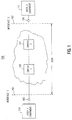
- ISDN may be viewed as a network 100 that provides end-to-end digital connectivity to support a wide range of user services, such as voice, data and video, to which such users have access utilizing standard, multi-purpose user-network interfaces (e.g. interface 101).
- information derived from or destined for customer-provided equipment located at a user's premises e.g. equipment 110
- equipment 110 including such equipment as a telephone, personal computer, stereo, and/or television
- a medium 105 between the user's equipment (e.g. 110) and a centralized switch (e.g. switch 120) embedded in the network.
- the equipment originating the information is transparent to the switch in the sense that all information has the same manifestation so it can be switched and transported in the same manner (e.g., from switch 120 to switch 121 and eventually over medium 106 to equipment 111 via interface 102.)
- ISDN has a common set of rules so that different types of user equipment can request one or more standard services provided by the network.
- This is in contrast to conventional telecommunications wherein different types of equipment require different physical and logical interfaces to the network.
- a conventional telephone set utilizing the public telephone network typically communicates over a wire-pair connected to a central office; the telephone, as manipulated by the user, interacts with central office via a pre-determined protocol (e.g., DC current flow, dual tone multi-frequency signals, 20 Hz ringing signal) so as to access other users served by the telephone network.
- a cable TV service requires the deployment of another physical medium (e.g., a coaxial cable) and end-point conversion devices to effect the necessary TV transmission.
- ISDN obviates the need for a myriad of paths and protocols since ISDN is fully integrated, that is, a single network provides many kinds of services using a single set of interface rules to govern all equipment using the network.
- ISDN standards define the interface (e.g., interface 101 or 102 in FIG. 1) between the user and the network; the interface is expressed as a set of protocols, including a message set used to request services.
- the interface is expressed as a set of protocols, including a message set used to request services.
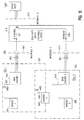
- FIG. 2 there is shown a pictorial representation of the protocol for a call set-up between a calling user and a called user; the protocol is composed of a time-ordered flow of ISDN signaling messages.
- the calling user initiates a call by picking-up the handset (arrow 201).
- the calling ISDN telephone itself responds by providing dial tone (arrow 202); there is no ISDN network involvement as yet.
- the term "network" is a shorthand for the ISDN combination of the switches and interfaces of FIG. 1.
- the calling user enters the telephone number (arrow 203) and hears the tones as the keys are pushed on the telephone keypad (arrow 204).
- the 'SETUP' message is one standard message from a set of messages defined for ISDN. Each message is composed of a series of information elements encoded with signaling information necessary to support the service desired at the moment, as discussed in more detail later. Thus, each type of message has a very specific purpose and its name usually connotes that purpose. For example, besides the 'SETUP' message, other messages to be exemplified in the call set-up of FIG. 2 include 'CONNECT' and 'ALERTING'.
- the 'SETUP' message is defined as the message sent by the calling user to the network and by the network to the called user to initiate a call connection.
- the network upon receipt of the 'SETUP' message, the network checks to be sure that the contents of the message are valid. Presuming the contents are valid, the network returns a 'CALL PROCEEDING' (arrow 206) message to the calling user to indicate that the call request is valid and that call set-up is in progress. At the called side of the desired connection, the network also sends a 'SETUP' message (arrow 207) to the called user; this 'SETUP' message contains different informational elements than the 'SETUP' message conveyed by the calling ISDN telephone since this 'SETUP' message is serving a different local interface, but the message is compiled in basically the same manner. In the situation illustrated in FIG.
- the called ISDN telephone's first message is a 'CALL PROCEEDING' message returned to the network (arrow 208).
- a ringing signal (arrow 210) is sounded by the called ISDN telephone to alert the called user.
- a follow-up 'ALERTING' message (arrow 209) is also sent from the called ISDN telephone to the network to inform the network that the called ISDN telephone has received the 'SETUP' message and is alerting (ringing) the called user.
- the network informs the calling ISDN telephone of both the 'CALL PROCEEDING' message (arrow 206) and the 'ALERTING' message (arrow 211).
- an audible ringback signal (arrow 212) is conveyed to the calling user by the called ISDN telephone.
- the response is a 'CONNECT' message (arrow 214) sent to the network from the called ISDN telephone.
- the network receives this message, it sends another 'CONNECT' message to the calling ISDN telephone so a path may be completed over a separate, logical channel to handle the actual human voice communication.
- Appropriate 'CONNECT ACKNOWLEDGE' messages (arrows 216 and 217) are sent from the network to the called ISDN telephone and from the calling ISDN telephone to the network, respectively, to complete the call set-up sequence.
- FIG. 3 there is shown a pictorial representation of the protocol, that is, the signaling messages, traversing the ISDN in order to take-down an established call set-up by the protocol of FIG. 2.
- the calling user initiates the take-down procedure by hanging up their handset (arrow 301).
- This activity causes a 'DISCONNECT' message sent by the calling ISDN telephone (arrow 302) to the network; at the same time, the calling ISDN telephone disconnects itself from the established B-channel.
- the network initiates a 'DISCONNECT' message (arrow 303) to the called user, and returns the 'RELEASE' message (arrow 305) to the calling user.
- the calling ISDN telephone sends a 'RELEASE COMPLETE' message (arrow 307) to the network and the network releases the B-channel at this interface.
- the called party will also at some point hang-up their handset (arrow 304), which causes a 'RELEASE' message (arrow 306) to be sent from the called ISDN telephone to the network.
- the network releases the B-channel at this interface and sends a 'RELEASE COMPLETE' message (arrow 308) to the called ISDN telephone, which also releases the B-channel.
- ISDN provides at least two basic types of channels that are differentiated by their function and transmission rate; these channels are referred to above as the D-channel and the B-channel.
- the D-channel's main purpose is that of carrying user-network signaling messages. All ISDN equipment exchange similar messages with the network to request services. The contents of the signaling messages vary with the equipment -- an ISDN telephone would request different services than an ISDN television. In each case, however, the D-channel conveys the services requests.
- the D-channel typically operates at 16 kbps for a basic rate service offering.
- Signals exchanged on the D-channel describe the type of service that the user is requesting.
- an ISDN telephone may desire a connection operating at 64 kbps for the support of a human voice conversation.
- This user request is translated to a request for a communication channel, and such a service is granted by allocating a so-called bearer channel (hence B-channel).
- bearer channel so-called bearer channel
- FIG. 2 it was pointed out that the 'CONNECT' message caused a distinct logical path to be set-up for communicating the human voice conversation; specifically, this distinct logical path is a B-channel.
- the partitioning between the D and B channels is shown on the left-hand side of FIG. 2, wherein all set-up messages utilize the D-channel, but the actual communication makes use of the B-channel.
- the primary function of the B-channel is to carry voice, data, and video. No service requests from the user are conveyed by the B-channel; this is strictly the domain of the D-channel.
- a B-channel has
- ISDN currently defines different access interfaces (e.g. interface 101 of FIG. 1) to the network; one of these is referred to as the basic rate interface (BRI).
- the access interfaces specify the rate at which the underlying physical medium will operate and the number of available B-channels and D-channels.
- the BRI is composed of one D-channel and two B-channels.
- the user data rate on the BRI is 144 kbps (2 at 64 kbps + 16 kbps), although additional signaling for the physical connection requires that the BRI operated at a total bit rate of 192 kbps.
- the ISDN protocols for the D-channel are encompassed by three layers, as outlined below:
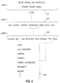
- FIG. 4 depicts the interpretation of the data bit stream propagated by layer 1 over a BRI.
- the bit stream encompassed by time line 410 uses pseudo-ternary signaling and is formed by interleaving B-channel and D-channel bits. Focusing on only the D-channel bits of this overall BRI bit stream, as depicted by the time line 420, it is shown that certain higher-level information is conveyed at layer 2.
- the initial eight bits compose a Flag field
- a certain number of the next-arriving bits comprise an Address field
- the Information field comes a stream of bits representing the Control field
- the Information field comes a stream of bits representing the Control field
- the Information field comes a stream of bits representing the Control field
- the Information field comes a stream of bits representing the Control field
- the Information field comes a stream of bits representing the Control field
- the Information field is a focal point.
- the Information field can be further subdivided into a number of other fields for interpretation at layer 3.
- the one that conveys the signaling messages is denoted as Message Type along time line 430.
- Various signaling messages which can be conveyed by this field are depicted by inclusion bracket 440.
- Such messages as 'SETUP', 'CALL PROCEEDING', ..., and 'RELEASE' which have already been discussed, are listed.
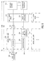
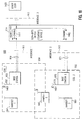
- FIG. 5 Such a high-level block diagram of the EWSD architecture arranged with ISDN is shown in FIG. 5.
- System 500 is composed of a limited number of loosely coupled subsystems which are each largely self-sufficient.
- Switching network 510 is the primary interconnection point to all the subsystems. Switching network 510 is composed of both time and space stages and it is virtually non-blocking.
- Coordination processor 515 is responsible for total system integrity as well as a part of call processing.
- Processor 515 does only those parts of the call processing functions which are naturally performed best by a centralized controller. These functions include switching network 510 path set up, final translation and routing and general call control coordination. All other call processing functions like signaling, digit collection and feature handling are done in line/trunk group 520.
- Line/truck group 520 is the subsystem which terminates numerous digital line carriers on both its incoming (523) and outgoing (522) ports.
- Group processor 525 in line/trunk group 520 manages all the control functions of this subsystem.
- Digital line unit 530 performs a concentration function and terminates a number of incoming BRIs exemplified by BRI 541.
- Digital line unit controller 534 provides for communication between digital line unit 530 and line/trunk group 520.
- Separator 532 of unit 530 handles the three layers of the D-channel and effects separation of the D- and B-channels.
- Microprocessor 533 handles D-channel protocol signaling and packages the protocol information into an internal format which, in turn, is made available to group processor 525 to control line/truck group 520 and is also made available to switching network 510 for switching activity.
- Line/trunk group 520 and digital line unit 530 may be replicated as needed (e.g. group 521 and line unit 531) to satisfy system capacity requirements.
- ISDN for this illustrative arrangement encompasses both system 500 as well as exemplary ISDN interface 550.
- EKTS Electronic Key Telephone Service
- DNs multiple directory numbers
- a given DN can also be accessed by more than one user, i.e., from more than one user equipment, on the same ISDN interface and/or different interfaces.
- two or more users with access to the same DN can be simultaneously bridged onto the same call established for that DN.
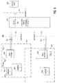
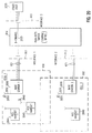
- FIG. 6 is essentially the architecture of FIG. 5 recast for particular discussion of the EKTS features.
- FIG. 6 depicts system 600 having digital switching system 500 (see FIG. 5) serving three ISDN interfaces 620-622.
- Interface 620 provides basic rate interface (BRI) 630 to user terminals 640 and 641, whereas interface 621 provides BRI 631 to user terminal 642 and interface 622 provides BRI 661 to calling user 660.
- Terminal 640 is coupled to BRI 630 via connector 650 (e.g. NT1/NT2), and terminal 641 is coupled to BRI 630 via connector 651 (e.g. NT1/NT2).
- Terminal 642 has connector 652 (e.g. NT1/NT2) as the coupling mechanism to BRI 631.
- Each BRI 630 or 631 is depicted as being composed of a (dashed line) D-channel (e.g. 632) and two (solid line) B-channels (e.g., 633 and 634)).
- Terminal 640 is depicted for illustrative purposes as having three DN appearances, namely, '5110', '5210' and '5310', whereas terminal 641 has two DN appearances '5110' and '5210', with terminal 642 having only DN '5210' as an appearance.
- Such DNs usually have a push-button key appearance on the face of the terminal, as exemplified by key 645 on terminal 640; oftentimes, colored lights may be displayed through translucent panels formed integral to the key so as to provide alerting functions to the user -- such panels are shown as 'red' (R) display panel 646 and 'green' (G) display panel 647 formed as part of key 645.
- a user of terminal 640, 641, or 642 may initiate an outgoing call to a called user outside of EKTS by pushing the appropriate DN key, say DN '5210'.
- the calling EKTS telephone provides status information to the calling user, such as steady red and green key panel lights on key 645 when the call is established.
- the other two terminals (641 and 642) are alerted to the ongoing activity by an appropriate alerting signal, such as a steady red key panel light on its DN '5210' appearance. Such an indication will remain in effect during the remainder of the call connection for the non-participating terminals 641 and 642.
- each user of terminals 640-642 receives an alerting signal (such as both a ringing signal and a blinking red panel light on key '5210') to indicate that there is an incoming call on each appearance of DN '5210'.
- an alerting signal such as both a ringing signal and a blinking red panel light on key '5210'
- the remaining two users receive an indication that the DN is active (such as a steady red panel light), while the answering terminal 640 will have another status indicator (such as steady red and green panel lights).
- the signaling to establish the connection between calling user 660 and terminals 640-642 is conveyed by both D-channels 632 and 635; once a connection is established between calling user 660 and called user of terminal 640, the users communicate over a B-channel, such as channel 633. More details pertaining to the set-up of this call will be covered shortly.
- the user of terminal 641 may bridge onto the call established between calling user 660 and terminal 640 merely by pushing the key associated with DN '5210'; prior to pushing the key, there is a steady red light indicator, and after the key is pushed, both steady red and green lights appear on the key panels of the bridging user's DN '5210'. It is possible at this time for the original called user of terminal 640 to disconnect from the established connection by again pushing the '5210' DN key, which turns off the green light but maintains the red light on the key panel as an indication of the remaining established connection.
- EKTS EKTS features
- the description of the EKTS features to this point has been purposely general in nature so that the essentials of the features could be presented before any further complexities are introduced.
- the complexities involve the ISDN signaling messages which are propagated over the D-channels of the various BRIs comprising an ISDN service offering to set-up, bridge, or take-down a call.
- TR-TSY-000205 entitled "ISDN Electronic Key Telephone Service", Issue 1, December 1988, published by Bellcore.
- EKTS terminal supports certain D-channel signaling messages not present in a more basic ISDN offering. For instance, with reference to FIG. 6, when calling user 660 directs a call to a DN (e.g., '5210'), the call is offered to each terminal 640-642 with a 'SETUP' message; this message is composed of the called party DN, bearer information to be used by the terminals for compatibility checking, and the type of alerting to be applied, as conveyed by the various layers depicted in FIG. 4.
- a called user e.g. terminal 640
- all other terminals will receive a 'KEY HOLD' message. This 'KEY HOLD' message is interpreted by each of the other terminals as notification that the call has been answered by another user, that is, the call is no longer alerting.
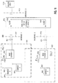
- FIG. 7 is a pictorial representation of the ISDN user-network protocol to set-up a call between a calling user outside EKTS and a called user served by EKTS.
- FIG. 7 is commensurate with FIG. 2 for comparison purposes to distinguish a non-EKTS service with an EKTS service in an ISDN environment. It should be noted however, for conciseness, that the actions (such as "pick up handset") of the calling user and called user, as explicitly shown in FIG. 2, have not been shown in FIG. 7; one skilled in the art may readily comprehend the actions now required of the users in FIG. 7 given the discussion of FIG. 2. With reference to FIG.
- the non-EKTS calling ISDN telephone transmits a 'SETUP' message (arrow 700) to the network.
- the network sends 'SETUP' messages (arrows 701 and 702) to EKTS users A and B (say terminals 640 and 641 in FIG. 6; terminal 642 is ignored in this discussion for brevity).
- Both users A and B respond with the standard 'CALL PROCEEDING' and 'ALERTING' messages (arrows 703,706 and 704,707, respectively).
- 'ALERTING' message 705 is sent from the network to the calling ISDN telephone.
- a 'CONNECT' message (arrow 708) is transmitted from EKTS user A to the network.
- the network responds by sending a 'CONNECT' message (arrow 709) to the calling ISDN telephone.
- the network sends a 'KEY HOLD' message (arrow 711) to EKTS user B to signal the fact that another user on EKTS has answered the call.
- the B-channel (dashed line 713) between the calling ISDN telephone and EKTS user A is established.
- FIG. 7 (which is now to be contrasted with FIG. 3), it is now supposed that the calling ISDN telephone terminates the call; this leads to a 'DISCONNECT' message (arrow 714) being transmitted to the network.
- the network responds by sending a 'DISCONNECT' message (arrow 715) to the active EKTS user A and a 'RELEASE' message (arrow 716) to the non-participating EKTS user B.
- a 'RELEASE' message (arrow 717) is sent from the network to the calling ISDN telephone.
- Both the calling ISDN telephone and EKTS user B respond by sending 'RELEASE COMPLETE' messages (arrows 718 and 721, respectively) to the network; on the other hand, the network sends a 'RELEASE' message (arrow 719) and awaits a 'RELEASE COMPLETE' message (arrow 720) to thereby complete the take-down of the established call.
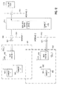
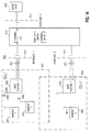
- FIG. 8 is a pictorial representation of the ISDN user-network protocol setting-up a call to a called user outside EKTS from a calling user served by EKTS, then the bridging of another user served by EKTS onto the established call, and finally the dropping off of the original calling user from the established call.
- the process is initiated by the calling terminal of EKTS user A sending a 'SETUP' message (arrow 800) to the network.
- the network responds by sending a 'SETUP' message (arrow 801) to the called ISDN telephone; also, the network responds to the original 'SETUP' message by conveying a 'KEY SETUP' message (arrow 802) to EKTS user B.
- the network sends the 'CALL PROCEEDING' message (arrow 803) to calling EKTS user A.
- the called ISDN telephone responds with the usual 'CALL PROCEEDING' and 'ALERTING' messages (arrows 804 and 805).
- EKTS user B responds with a 'KEY SETUP ACKnowledge' message (arrow 806) to inform the network that the earlier 'KEY SETUP' message was received.
- 'ALERTING' messages (arrows 807 and 808) are sent from the network to both EKTS users A and B.
- a 'CONNECT' message (arrow 809) is conveyed to the network; in turn, the network sends 'CONNECT' messages (arrows 810 and 811) to EKTS users A and B, respectively.
- 'CONNECT ACKnowledge' messages (arrows 812, 813, and 814) are appropriately transmitted from the network or to the network, as needed.
- a B-channel (dashed line 830) is established between the called ISDN telephone and the calling EKTS user A.
- EKTS user B With the call established, EKTS user B is aware of the established call via an appropriate indicator such as a panel key light, and EKTS user B may desire to bridge onto the established call. For example, EKTS user B may push the DN key of the established call; this results in a 'RETRIEVE' message (arrow 815) being sent to the network to indicate user B's desire to bridge onto the established call.
- the network responds by, first, sending a 'NOTIFY' message (arrow 816) to EKTS user A to indicate the fact that another EKTS party is entering the established connection, and secondly, the network sends a 'RETRIEVE ACKnowledge' message (arrow 817) to EKTS user B to inform this user that bridging will occur.
- a B-channel then is arranged to link both users A and B with the called ISDN telephone.
- EKTS user A now wishes to drop from the established call, a 'DISCONNECT' message (arrow 818) is transmitted to the network by EKTS user A.
- the network responds by sending a 'KEY RELEASE' message (arrow 819) to EKTS user A to inform this user that its B-channel connection will be dropped (as depicted now by dashed line 832 connecting only EKTS user B with the called ISDN telephone).
- EKTS user B since only EKTS user B is on the established call from the perspective of EKTS, if user B disconnects, then the call is to be terminated. This is shown by the 'DISCONNECT' message (arrow 820) being transmitted from EKTS user B to the network.
- a 'DISCONNECT' message (arrow 814) is sent to the called ISDN telephone by the network; moreover, the network sends 'RELEASE' messages (arrows 822 and 823) to EKTS users A and B, respectively.
- the called ISDN telephone responds to its 'DISCONNECT' message with a 'RELEASE' message (arrow 824) to the network.
- both EKTS users A and B respond to the network with 'RELEASE COMPLETE' messages (arrows 826 and 827, respectively).
- FIG. 9 there is shown cellular system 900 which is composed of: an ISDN encompassing ISDN-EKTS switch 914 (e.g. system 500 of FIG. 5) and ISDN interfaces 911, 912 and 913; base stations 950 and 970, with base station 950 serving mobile handsets 941 and 942, respectively, within cell 931, and wherein base station 970 serves handset 960 within cell 932; and called user 920 connected to interface 913.
- base station 950 is connected to interface 911 via BRI 951
- base station 970 is connected to interface 912 with BRI 971.
- each base station represents an additional type of terminal equipment in the category of an ISDN telephone, TV, or EKTS terminal.
- each base station is configured so that the port connected to the basic rate interface is implemented to process the EKTS features elaborated upon earlier.
- a second base station port functions in the conventional cellular sense as a transmitter/receiver ("transceiver") of wireless signals.
- system 900 and the concomitant methodology corresponding to the operation of system 900 utilize at least one ISDN BRI (951,971) and at least one ISDN interface (911,912) to serve base stations 950 and 970.
- Each cellular mobile user such as handset 941, 942, or 960, is assigned a unique EKTS directory number (DN).
- DN EKTS directory number
- CO 914 treats base stations homing on it as ISDN-EKTS terminals each of which serves all DNs for the given cellular mobile communication application, that is, all DNs appear at all base stations.
- FIG. 10 depicts that the established call between handset 941 and called user 920 utilizes B-channel 1082.
- the two-way nature of the communication channel between base station 950 and handset 941 is depicted at base station 950 by transmitted signal 1045 propagated from antenna 952 for reception by antenna 943 of handset 941.
- base station 950 can address handset 941 directly with the ISDN DN or extension.
- a base station may use a terminal identifier other than an EKTS DN to address the handsets, and the terminal identifier of the calling handset must be translated to an EKTS DN or extension.
- This translation may be accomplished by the base station or, optionally, by central office 914 in this illustrative case. If the central office does the translation, then the terminal identifier of the originating handset can be passed to the central office using an appropriate sub-field in the information fields of layer 3 (e.g. fields 430 of FIG. 4).
- FIG. 11 there is again shown basic system 900 as originally depicted in FIG. 9.
- the primary difference between FIG. 11 compared to FIG. 9 is that the incoming calling user 1120 initiates a call set-up to a cellular mobile user, say handset 960 for discussion purposes.
- the following sequence of steps occurs to complete this call set-up (this sequence of steps is commensurate with the steps described in detail with respect to FIG. 7 in setting up a B-channel between a calling ISDN telephone and EKTS user A -- accordingly, the following sequence may be set forth with some brevity due to these previous teachings):
- base station 970 can address handset 960 directly with the ISDN DN or extension.
- the base station may use a terminal identifier other than an EKTS DN to address the handsets, and the terminal identifier of the calling handset must be translated to an EKTS DN or extension.
- This translation may be accomplished by the base station or, optionally, by central office 914 in this illustrative case. If the central office does the translation, then the terminal identifier of the originating handset can be passed to the central office using an appropriate sub-field in the information fields of layer 3 (e.g. fields 430 of FIG. 4).
- the final major service provisioning area is the arrangement for handing off a call from one base station to another as the cellular mobile user crosses from an original cell to a secondary cell.
- This aspect of the invention is presented with reference to FIGS. 14-18.
- FIG. 14 there is shown again basic system 900 as originally depicted in FIG. 9.
- the starting point for the immediate discussion is the presumption that a stable communication connection over a B-channel has been established between a cellular mobile user and another user -- as illustrated, B-channel 1411 connects handset 942 and other user 1420.
- the communication connection may have been established by the procedure discussed in either of the two preceding sections on service provisioning.
- base stations 950 and 970 can address handset 942 directly with the ISDN DN or extension.
- the base stations may use a terminal identifier other than the EKTS DN to address the handsets, and the terminal identifier of the calling handset must be translated to an EKTS DN or extension.
- This translation may be accomplished by the base station or, optionally, by central office 914 in this illustrative case. If the central office does the translation, then the terminal identifier of the originating handset can be passed to the central office using an appropriate sub-field in the information fields of layer 3 (e.g. fields 430 of FIG. 4).
- FIG. 19 depicts a high-level block diagram of an illustrative arrangement of a base station (say base station 950) to provide the required functionality.
- base station 950 is composed of radio transceiver 955, with associated antenna 952, ISDN-EKTS interface 953, and interposed radio-ISDN/EKTS converter 954.
- Radio transceiver 955 serves as a radio port to both receive incoming radio signals from the cellular mobiles users and transmit outgoing radio signals from the base station.
- Interface 953 serves as a termination port for BRI 951.
- converter 940 serves to convert the digital information from interface 953 to commensurate radio signals for transceiver 955 and vice versa.
- the movement of a handset is detected by the base station tracking the location of the handset.
- the tracking is effected by the handset, that is, the handset is arranged with circuitry and appropriate logic to determine if and when a change of cells is required. This determination is accomplished by arranging each base station for continuous propagation of a cell identifier that informs the handsets within the cell of which base station serves that corresponding cell.
- a PCS serving area or cellular region is served by a frequency spectrum, and this spectrum is subdivided into frequency bands.
- Each band serves a different base station so that neighboring cells will have different frequency bands.
- a number of channels is provided via Time Division Multiplexing (TDM) and the channels are shared among all the handsets in a given cell.
- TDM Time Division Multiplexing
- Each handset runs two on-going quality processes. The first process involves a quality check on the operating channel to determine the quality of the reception relative to a threshold. If the quality falls below a threshold, the handset will look for another channel within the band to switch to.
- the second process involves a quality check on the entire band. If the reception degrades to the point where the handset is receiving another base station signal with better quality as measured relative to a threshold, the given handset initiates a message in the band of the other base station to see if there is an open channel. If so, the handset emits an automatic link transfer command to have the latter base station switch the communication connection to the open channel.
- the handset monitors both quality cycles constantly and whenever the handset detects that there is a better band and channel available, the handset will request from the base station that owns the resources (band and channel) to change to that resource.
- each DN is assigned to every base station so that every cell serves every DN.
- the communication connection is carried by one of the channels within a band.
- FIG. 20 illustrates an established communication connection from PCS handset 2042 to other user 2020 over B-channel 2025.
- the primary difference between FIG. 20 and the previous FIGS. 9-18 resides in PCS handsets 2041, 2042 and 2060, and base stations 2050 and 2070.
- all base stations continuously emit a radio signal to enable the handsets to monitor the quality of the reception and negotiate a change of band or channel or both when the quality of the active band or channel degrades.
- B-channel 2025 connects handset 2042 and other user 2020.
- the communication connection may have been established by a procedure similar to service provisioning for either incoming or outgoing calls described above.
- the following sequence of steps occurs to maintain the communication connection as handset 2042 migrates from cell 931 to cell 932 (this sequence of steps is commensurate with the steps described in detail with respect to FIG. 8 and FIGS. 14-18, with special emphasis on the bridging procedures associated with user B bridging onto the call, and then user A dropping off the call -- accordingly, the following sequence may be set forth with some brevity due to these previous teachings):
Landscapes
- Engineering & Computer Science (AREA)
- Computer Networks & Wireless Communication (AREA)
- Signal Processing (AREA)
- Mobile Radio Communication Systems (AREA)
- Edible Oils And Fats (AREA)
- Coloring Foods And Improving Nutritive Qualities (AREA)
- Investigating Or Analysing Biological Materials (AREA)
- Crystals, And After-Treatments Of Crystals (AREA)
Claims (17)
- Verfahren zum Aufbau einer Kommunikationsverbindung zwischen einem anrufenden Mobilfunkteilnehmer (941) und einem angerufenen Teilnehmer (920), wobei Mobilfunkteilnehmer (941, 942) Zugriff auf ein Mobilfunknetz (900) haben, das eine Anzahl Zellen (931, 932) abdeckt, die von einer entsprechenden Anzahl Basisstationen (950, 970) bedient werden, und wobei alle diese Basisstationen (950, 970) mit der selben Zentralstelle (Co) in einem dienstintegrierenden digitalen Fernmeldenetz (ISDN) verbunden sind, und jede Basisstation (950, 970) mit einen Hochfrequenzanschluss (955) ausgestattet ist, um mit den Mobilfunkteilnehmern (941, 942) in der Zelle (931), die zu jeder Basisstation (950) gehört, Hochfrequenzsignale auszutauschen, dadurch gekennzeichnet, dass die Zentralstelle (Co) zudem dafür eingerichtet ist, den Basisstationen (950, 970) den Electronic Key Telephone Service (EKTS) zu bieten, und das Verfahren die Schritte umfasst:das Ausrüsten einer jeden Basisstation (950, 970) mit einem ISDN-gestützten EKTS-Anschluss (953) zum Austauschen von EKTS-Signalisiermeldungen und Informationen mit der Zentralstelle (Co) über eine Zugriffsschnittstelle (911), die einen D-Kanal und einen B-Kanal besitzt, und mit einem Konverter (954), der die Hochfrequenzsignale und die EKTS-Signalisiermeldungen und Informationen ineinander umsetzt,abhängig von einer Anforderung (944) des anrufenden Mobilfunkteilnehmers (941) zum Aufbau der Kommunikationsverbindung, die über den Hochfrequenzanschluss (955) einer der Basisstationen (950) empfangen wurde, die der Zelle (931) dient, in der sich der anrufende Mobilfunkteilnehmer (941) aufhält, das Umsetzen der Anforderung (944) auf ISDN-gestützte EKTS-D-Kanal-VerbindungsaufbauProtokollsignalisiermeldungen (981) und Austauschen der Protokollsignalisiermeldungen zwischen der einen Basisstation (950) und der Zentralstelle (Co); undbei einer Antwort des angerufenen Teilnehmers (920) auf die Protokollsignalisiermeldungen, das Aufbauen der Kommunikationsverbindung zwischen dem anrufenden Mobilfunkteilnehmer (941) und dem angerufenen Teilnehmer (920), wobei die Kommunikationsverbindung einen ISDN-B-Kanal (1082) zwischen der einen Basisstation (950) und dem angerufenen Teilnehmer (920) umfasst.
- Verfahren nach Anspruch 1, wobei der Aufbauschritt die Schritte enthält: Umsetzen der an einer der Basisstationen (950) empfangenen B-Kanal-Information in abgehende Hochfrequenz-Informationssignale (1045) für die Übertragung zum anrufenden Mobilfunkteilnehmer (941), und Umsetzen der eingehenden Hochfrequenz-Informationssignale (944), die vom anrufenden Mobilfunkteilnehmer (941) empfangen wurden, in Information, die für eine Übertragung über den B-Kanal (1082) geeignet ist, womit die Kommunikationsverbindung zwischen dem anrufenden Mobilfunkteilnehmer (941) und dem angerufenen Teilnehmer (920) vervollständigt wird.
- Verfahren zum Aufbau einer Kommunikationsverbindung zwischen einen Teilnehmer (1120), dessen Anruf eingeht, und einem angerufenen Mobilfunkteilnehmer (960), wobei die Mobilfunkteilnehmer (960) Zugriff auf ein Mobilfunknetz (900) haben, das eine Anzahl Zellen (931, 932) abdeckt, die von einer entsprechenden Anzahl Basisstationen (950, 970) bedient werden, wobei alle diese Basisstationen (950, 970) mit der gleichen Zentralstelle (Co) in einem dienstintegrierenden digitalen Fernmeldenetz (ISDN) verbunden sind, und jede Basisstation (950, 970) mit einem Hochfrequenzanschluss (955) ausgestattet ist, um Hochfrequenzsignale mit den Mobilfunkteilnehmern (960) in der Zelle (931, 932) auszutauschen, die zu jeder Basisstation (950, 970) gehört, dadurch gekennzeichnet, dass die Zentralstelle (Co) zudem dafür eingerichtet ist, den Basisstationen (950, 970) den Electronic Key Telephone Service (EKTS) zu bieten, und das Verfahren die Schritte umfasst:das Ausrüsten einer jeden Basisstation (950, 970) mit einem ISDN-gestützten EKTS-Anschluss (953) zum Austauschen von EKTS-Signalisiermeldungen und Informationen mit der Zentralstelle (Co) über eine Zugriffsschnittstelle (912), die einen D-Kanal und einen B-Kanal besitzt, und mit einem Konverter (954), der die Hochfrequenzsignale und die EKTS-Signalisiermeldungen und Informationen ineinander umsetzt,abhängig von einer Anforderung (SETUP), die in der Zentralstelle (Co) vom anrufenden Teilnehmer (1120) eingeht, die Kommunikationsverbindung mit dem angerufenen Mobilfunkteilnehmer (960) herzustellen, das Austauschen von D-Kanal-Verbindungsaufbau-Protokollsignalisiermeldungen (1181, 1182), die eine Kennung des angerufenen Mobilfunkteilnehmers (960) enthalten, zwischen der Zentralstelle (Co) und dem ISDN-gestützten EKTS-Anschluss einer jeden Basisstation (950, 970), undbei einer Antwort des angerufenen Mobilfunkteilnehmers (960) auf die Protokollsignalisiermeldungen, das Aufbauen der Kommunikationsverbindung zwischen dem anrufenden Teilnehmer (1120) und dem angerufenen Mobilfunkteilnehmer (960), wobei die Kommunikationsverbindung einen ISDN-B-Kanal (1184) zwischen dem anrufenden Teilnehmer (1120) und einer der Basisstationen (970) umfasst, die zu der Zelle (932) gehört, in der sich der angerufene Mobilfunkteilnehmers (960) aufhält.
- Verfahren nach Anspruch 3, wobei der Aufbauschritt die Schritte enthält: Umsetzen der Signalisiermeldungen in jeder Basisstation in ein Hochfrequenz-Aufbausignal (1145, 1172), das die Anforderung anzeigt, und das Aussenden des Hochfrequenz-Aufbausignals (1145, 1172) vom Hochfrequenzanschluss einer jeden Basisstation (950, 970),Erfassen des Hochfrequenz-Aufbausignals (1172) durch jeden Mobilfunkteilnehmer (960) und Identifizieren des angerufenen Mobilfunkteilnehmers (960) durch die Kennung (DN) im Hochfrequenz-Aufbausignal, undRücksenden eines entsprechenden Hochfrequenz-Aufbausignals (1262) vom angerufenen Mobilfunkteilnehmer (950) zu der einen Basisstation (970).
- Verfahren nach Anspruch 4, wobei der Aufbauschritt zudem die Schritte enthält: Umsetzen der an der einen Basisstation (970) empfangenen B-Kanal-Information in abgehende Hochfrequenz-Informationssignale (1172), die zum angerufenen Mobilfunkteilnehmer (960) übertragen werden, und Umsetzen der eingehenden Hochfrequenz-Informationssignale (1262), die vom angerufenen Mobilfunkteilnehmer (960) empfangen werden, in Information, die sich für die Übertragung über den B-Kanal eignet, womit die Kommunikationsverbindung zwischen dem anrufenden Mobilfunkteilnehmer (1120) und dem angerufenen Teilnehmer (960) vervollständigt wird.
- Verfahren nach Anspruch 3, wobei der Schritt des Austauschens der D-Kanal-Verbindungsaufbau-Protokollsignalisiermeldungen die Schritte enthält:Senden einer EKTS-'SETUP'-Meldung von der Zentralstelle (Co) zum ISDN-EKTS-Anschluss einer jeden Basisstation (950, 970), undSenden einer EKTS-'CALL PROCEEDING'-Meldung und einer EKTS-'ALERTING'-Meldung von jeder Basisstation (950, 970) zur Zentralstelle (Co).
- Verfahren nach Anspruch 6, wobei der Schritt des Aufbauens der Kommunikationsverbindung die Schritte umfasst:Senden einer EKTS-'CONNECT'-Meldung von der einen Basisstation (950, 970) zur Zentralstelle (Co),Senden einer entsprechenden 'CONNECT'-D-Kanal-Meldung von der Zentralstelle (Co) zum anrufenden Teilnehmer (1120),Senden einer EKTS-'CONNECT ACKNOWLEDGE'-D-Kanal-Meldung vom anrufenden Teilnehmer (1120) zur Zentralstelle (Co),Senden einer entsprechenden 'CONNECT ACKNOWLEDGE'-D-Kanal-Meldung von der Zentralstelle (Co) zu der einen Basisstation (970)
- Verfahren zum Weiterreichen einer bestehenden Kommunikationsverbindung zwischen einem Mobilfunkteilnehmer (942) und einem weiteren Teilnehmer (1420), wobei die Mobilfunkteilnehmer (942) Zugriff auf ein Mobilfunknetz (900) haben, das eine Anzahl Zellen (931, 932) abdeckt, die von einer entsprechenden Anzahl Basisstationen (950, 970) bedient werden, und wobei alle diese Basisstationen (950, 970) mit der selben Zentralstelle (Co) in einem dienstintegrierenden digitalen Fernmeldenetz (ISDN) verbunden sind, und jede Basisstation (950, 970) mit einen Hochfrequenzanschluss (955) ausgestattet ist, um mit den Mobilfunkteilnehmern (942) in der Zelle (931, 932), die zu jeder Basisstation (950, 970) gehört, Hochfrequenzsignale auszutauschen, dadurch gekennzeichnet, dass die Zentralstelle (Co) zudem dafür eingerichtet ist, den Basisstationen (950, 970) den Electronic Key Telephone Service (EKTS) zu bieten, und das Verfahren die Schritte umfasst:das Ausrüsten einer jeden Basisstation (950, 970) mit einem ISDN-gestützten EKTS-Anschluss (953) zum Austauschen von EKTS-Signalisiermeldungen und Informationen mit der Zentralstelle (Co) über eine Zugriffsschnittstelle (911), die einen D-Kanal und einen B-Kanal besitzt, und mit einem Konverter (954), der die Hochfrequenzsignale und die EKTS-Signalisiermeldungen und Informationen ineinander umsetzt,abhängig vom Mobilfunkteilnehmer (942), der sich von einer Ursprungszelle (931), die von einer Ursprungsbasisstation (950) bedient wird, in eine zweite Zelle (932) bewegt, das Erfassen der Hochfrequenzsignale (1402), die der Mobilfunkteilnehmer (942) aussendet, in einer zweiten Basisstation (970), die die zweite Zelle (932) abdeckt,das Aufschalten der zweiten Basisstation auf die bestehende Kommunikationsverbindung (1411) durch das Austauschen von D-Kanal-Protokollsignalisiermeldungen (1602) mit der Zentralstelle (Co), damit eine Dreiweg-B-Kanal-Kommunikationsverbindung hergestellt wird, an der die ursprüngliche und die zweite Basisstation (950, 970) beteiligt sind,das Benachrichtigen der Ursprungsbasisstation (950) mit Hilfe von D-Kanal-Protokollsignalisiermeldungen (1603) zwischen der Zentralstelle (Co) und der Ursprungsbasisstation (950) von der Aufschalthandlung der zweiten Basisstation (970), unddas Abtrennen der Ursprungsbasisstation (950) von der Dreiweg-B-Kanal-Kommunikationsverbindung, damit eine Zweiwegverbindung zwischen dem Mobilfunkteilnehmer (942) und dem anderen Teilnehmer (1420) hergestellt wird, wobei die Zweiwegverbindung eine B-Kanal-Kommunikationsverbindung (1602) zwischen der zweiten Basisstation (970) und der Zentralstelle (Co) umfasst.
- Verfahren nach Anspruch 8, wobei der Abtrennschritt zum Herstellen der Zweiwegverbindung die Schritte umfasst: das Umsetzen der an der zweiten Basisstation (970) empfangenen B-Kanal-Information (1602) in abgehende Hochfrequenz-Informationssignale (1601), die zum Mobilfunkteilnehmer (942) übertragen werden, und das Umsetzen der vom Mobilfunkteilnehmer eingehenden Hochfrequenz-Informationssignale (1402) in Information, die für die Übertragung über den B-Kanal zum anderen Teilnehmer geeignet ist, und damit das Abschließen des Weiterreichens der stabilen Kommunikationsverbindung zwischen dem Mobilfunkteilnehmer (942) und dem anderen Teilnehmer (1420).
- Verfahren nach Anspruch 8, zudem umfassend den Schritt des Sendens einer EKTS-'KEY SETUP'-D-Kanalmeldung von der Zentralstelle (Co) zur zweiten Basisstation (970) während des Aufbaus der bestehenden Kommunikationsverbindung, wobei der Aufschaltschritt den Schritt des Sendens einer EKTS-'RETRIEVE'-D-Kanalmeldung von der zweiten Basisstation (970) zur Zentralstelle (Co) enthält, und worin der Benachrichtigungsschritt den Schritt des Sendens einer EKTS-'NOTIFY'-D-Kanalmeldung von der Zentralstelle (Co) zur Ursprungsbasisstation (950) enthält.
- Verfahren zum Weiterreichen einer bestehenden Kommunikationsverbindung zwischen einem PCS-Mobilfunkteilnehmer (2042) und einem weiteren Teilnehmer (2020), wobei die PCS-Mobilfunkteilnehmer (2042) Zugriff auf ein Mobilfunknetz haben, das eine Anzahl Zellen (931, 932) abdeckt, die von einer entsprechenden Anzahl Basisstationen (2050, 2070) bedient werden, und wobei alle diese Basisstationen (2050, 2070) mit der selben Zentralstelle (Co) in einem dienstintegrierenden digitalen Fernmeldenetz (ISDN) verbunden sind, und jede Basisstation (2050, 2070) mit einen Hochfrequenzanschluss ausgestattet ist, um mit den PCS-Mobilfunkteilnehmern (2042) in der Zelle (931, 932), die zu jeder Basisstation (2050, 2070) gehört, Hochfrequenzsignale auszutauschen, dadurch gekennzeichnet, dass die Zentralstelle (Co) zudem dafür eingerichtet ist, den Basisstationen (2050, 2070) den Electronic Key Telephone Service (EKTS) zu bieten, und das Verfahren die Schritte umfasst:das Ausrüsten einer jeden Basisstation (2050, 2070) mit einem ISDN-gestützten EKTS-Anschluss zum Austauschen von EKTS-Signalisiermeldungen und Informationen mit der Zentralstelle über eine Zugriffsschnittstelle (911), die einen D-Kanal und einen B-Kanal besitzt, und mit einem Konverter, der die Hochfrequenzsignale und die EKTS-Signalisiermeldungen und Informationen ineinander umsetzt,das Zuweisen einer eindeutigen Kennung an jede Basisstation (2050, 2070) , so dass jeder PCS-Mobilfunkteilnehmer jede Basisstation identifizieren kann,wenn sich der PCS-Mobilfunkteilnehmer (2042) aus der Ursprungszelle (931), die von der Ursprungsbasisstation (2050) bedient wird, in eine zweite Zelle bewegt, die von einer zweiten Basisstation (2070) bedient wird, das Erfassen der Hochfrequenzsignale, die die Ursprungsbasisstation (2050) und zweite Basisstation (2070) aussenden,das Messen der Empfangsqualität der Ursprungsbasisstation (2050) und der zweiten Basisstation (2070) durch den PCS-Mobilfunkteilnehmer,immer dann, wenn die Empfangsqualität der zweiten Basisstation besser ist als die Empfangsqualität der Ursprungsbasisstation, das Auslösen einer Anforderung zum Übertragen der bestehenden Kommunikationsverbindung (2025) zur zweiten Basisstation (2070) durch den PCS-Mobilfunkteilnehmer (2042),das Aufschalten der zweiten Basisstation (2070) auf die bestehende Kommunikationsverbindung durch das Austauschen von D-Kanal-Protokollsignalisiermeldungen mit der Zentralstelle, damit eine Dreiweg-B-Kanal-Kommunikationsverbindung hergestellt wird, an der die ursprüngliche Basisstation (2050) und die zweite Basisstation (2070) beteiligt sind,das Benachrichtigen der Ursprungsbasisstation mit Hilfe von D-Kanal-Protokollsignalisiermeldungen (DISCONNECT) zwischen der Zentralstelle (Co) und der Ursprungsbasisstation (2050) von der Aufschalthandlung der zweiten Basisstation (2070),das Abtrennen der Ursprungsbasisstation von der Dreiweg-B-Kanal-Kommunikationsverbindung, damit eine Zweiweg-B-Kanal-Kommunikationsverbindung zwischen der zweiten Basisstation (2070) und der Zentralstelle (Co) hergestellt wird.
- Verfahren nach Anspruch 11, wobei der Abtrennschritt zum Herstellen der Zweiwegverbindung die Schritte umfasst: das Umsetzen der an der zweiten Basisstation (2070) empfangenen B-Kanal-Information in abgehende Hochfrequenz-Informationssignale (2072), die zum PCS-Mobilfunkteilnehmer (2042) übertragen werden, und das Umsetzen der vom PCS-Mobilfunkteilnehmer (2042) eingehenden Hochfrequenz-Informationssignale (2043) in Information, die für die Übertragung über den B-Kanal zum anderen Teilnehmer geeignet ist, und damit das Abschließen des Weiterreichens der stabilen Kommunikationsverbindung zwischen dem PCS-Mobilfunkteilnehmer (2042) und dem anderen Teilnehmer (2020).
- Verfahren nach Anspruch 12, zudem umfassend den Schritt des Sendens einer EKTS-'KEY SETUP'-D-Kanalmeldung von der Zentralstelle (Co) zur zweiten Basisstation (2070) während des Aufbaus der bestehenden Kommunikationsverbindung, wobei der Aufschaltschritt den Schritt des Sendens einer EKTS-'RETRIEVE'-D-Kanalmeldung von der zweiten Basisstation (2070) zur Zentralstelle (Co) enthält, und worin der Benachrichtigungsschritt den Schritt des Sendens einer EKTS-'NOTIFY'-D-Kanalmeldung von der Zentralstelle zur Ursprungsbasisstation (2050) enthält.
- Schaltungen zum Herstellen einer Kommunikationsverbindung zwischen einem anrufenden Mobilfunkteilnehmer (941) und einem angerufenen Teilnehmer (920), wobei die Mobilfunkteilnehmer (941, 942) Zugriff auf ein Mobilfunknetz (900) haben, das eine Anzahl Zellen (931, 932) abdeckt, die von einer entsprechenden Anzahl Basisstationen (950, 970) bedient werden, und wobei alle diese Basisstationen (950, 970) mit der selben Zentralstelle (Co) in einem dienstintegrierenden digitalen Fernmeldenetz (ISDN) verbunden sind, und jede Basisstation (950, 970) Vorrichtungen zur Verbindung mit einem Hochfrequenzanschluss (955) hat, um mit den Mobilfunkteilnehmern (941, 942) in der Zelle, die zu jeder Basisstation (950, 970) gehört, Hochfrequenzsignale auszutauschen, dadurch gekennzeichnet, dass die Zentralstelle (Co) zudem dafür eingerichtet ist, den Basisstationen (950, 970) den Electronic Key Telephone Service (EKTS) zu bieten, und die Schaltungen umfassen:eine Vorrichtung zum Ausrüsten einer jeden Basisstation (950, 970) mit einem ISDN-gestützten EKTS-Anschluss (953) zum Austauschen von EKTS-Signalisiermeldungen und Informationen mit der Zentralstelle (Co) über eine Zugriffsschnittstelle (911), die einen D-Kanal und einen B-Kanal besitzt, wobei die Ausrüstvorrichtung eine Einrichtung (954) enthält, die die Hochfrequenzsignale und die EKTS-Signalisiermeldungen und Informationen ineinander umsetzt,eine Einrichtung (954), die auf eine Anforderung (944) des anrufenden Mobilfunkteilnehmers (941) zum Aufbau der Kommunikationsverbindung anspricht, die über den Hochfrequenzanschluss (955) von einer der Basisstationen (950) empfangen wurde, die der Zelle (931) dienen, in der sich der anrufende Mobilfunkteilnehmer (941) aufhält, und die die Anforderung (944) in EKTS-D-Kanal-Verbindungsaufbau-Protokollsignalisiermeldungen (981) umsetzt,eine Vorrichtung (953), die von der Umsetzvorrichtung angestoßen wird und die Protokollsignalisiermeldungen zwischen der einen Basisstation (950) und der Zentralstelle (Co) austauscht, undeine Vorrichtung (951), die von der Austauschvorrichtung (953) angestoßen wird und die Kommunikationsverbindung aufbaut, wobei die Kommunikationsverbindung einen ISDN-B-Kanal (1082) zwischen der einen Basisstation (950) und dem angerufenen Teilnehmer (920) enthält.
- Schaltungen zum Herstellen einer Kommunikationsverbindung zwischen einem Teilnehmer (1120), dessen Anruf hereinkommt, und einem angerufenen Mobilfunkteilnehmer (960), worin Mobilfunkteilnehmer (960) Zugriff auf ein Mobilfunknetz (900) haben, das eine Anzahl Zellen (931, 932) abdeckt, die von einer entsprechenden Anzahl Basisstationen (950, 970) bedient werden, und wobei alle diese Basisstationen (950, 970) mit der selben Zentralstelle (Co) in einem dienstintegrierenden digitalen Fernmeldenetz (ISDN) verbunden sind, und jede Basisstation (950, 970) Vorrichtungen zum Verbinden mit einem Hochfrequenzanschluss (955) hat, um mit den Mobilfunkteilnehmern (960) in der Zelle (931, 932), die zu jeder Basisstation (950, 970) gehört, Hochfrequenzsignale auszutauschen, dadurch gekennzeichnet, dass die Zentralstelle (Co) zudem dafür eingerichtet ist, den Basisstationen (950, 970) den Electronic Key Telephone Service (EKTS) zu bieten, und die Schaltungen umfassen:Vorrichtungen zum Ausrüsten einer jeden Basisstation (950, 970) mit einem ISDN-gestützten EKTS-Anschluss (953) zum Austauschen von EKTS-Signalisiermeldungen und Informationen mit der Zentralstelle (Co) über eine Zugriffsschnittstelle (911), die einen D-Kanal und einen B-Kanal besitzt, wobei die Ausrüstvorrichtung eine Einrichtung (954) enthält, die die Hochfrequenzsignale und die EKTS-Signalisiermeldungen und Informationen ineinander umsetzt,eine Einrichtung, die auf eine in der Zentralstelle eingegangene Anforderung des Teilnehmers, dessen Anruf hereinkommt, zum Aufbau der Kommunikationsverbindung mit dem angerufenen Mobilfunkteilnehmer anspricht, und D-Kanal-Verbindungsaufbau-Protokollsignalisiermeldungen zwischen der Zentralstelle und dem ISDN-gestützten EKTS-Anschluss einer jeden Basisstation (950, 970) austauscht, die eine Kennung des angerufenen Mobilfunkteilnehmers enthalten, undeine Vorrichtung, die von der Austauschvorrichtung angestoßen wird und vom angerufenen Mobilfunkteilnehmer (942), der die Kennung besitzt, zum Aufbau der Kommunikationsverbindung zwischen dem anrufenden Teilnehmer (1120) und dem angerufenen Mobilfunkteilnehmer (942), wobei die Kommunikationsverbindung einen ISDN-B-Kanal (1184) zwischen dem anrufenden Teilnehmer (1120) und einer der Basisstationen (950) enthält, die zu der Zelle (931) gehören, in der sich der angerufene Mobilfunkteilnehmer (942) aufhält.
- Schaltungen zum Weiterreichen einer bestehenden Kommunikationsverbindung zwischen einem Mobilfunkteilnehmer (942) und einem weiteren Teilnehmer (1420), wobei Mobilfunkteilnehmer (942) Zugriff auf ein Mobilfunknetz (900) haben, das eine Anzahl Zellen (931, 932) abdeckt, die von einer entsprechenden Anzahl Basisstationen (950, 970) bedient werden, und wobei alle diese Basisstationen (950, 970) mit der selben Zentralstelle (Co) in einem dienstintegrierenden digitalen Fernmeldenetz (ISDN) verbunden sind, und jede Basisstation (950, 970) eine Vorrichtung hat, die sie mit einem Hochfrequenzanschluss (955) verbindet, um mit den Mobilfunkteilnehmern (942) in der Zelle (931, 932), die zu jeder Basisstation (950, 970) gehört, Hochfrequenzsignale auszutauschen, dadurch gekennzeichnet, dass die Zentralstelle (Co) zudem dafür eingerichtet ist, den Basisstationen (950, 970) den Electronic Key Telephone Service (EKTS) zu bieten, und die Schaltungen umfassen:eine Vorrichtung zum Ausrüsten einer jeden Basisstation mit einem ISDN-gestützten EKTS-Anschluss (953) zum Austauschen von EKTS-Signalisiermeldungen und Informationen mit der Zentralstelle (Co) über eine Zugriffsschnittstelle (911), die einen D-Kanal und einen B-Kanal besitzt, wobei die Ausrüstvorrichtung eine Vorrichtung (954) besitzt, die die Hochfrequenzsignale und die EKTS-Signalisiermeldungen und Informationen ineinander umsetzt,eine Vorrichtung, die auf einen Mobilfunkteilnehmer anspricht, der sich von einer Ursprungszelle (931), die von einer Ursprungsbasisstation (950) bedient wird, in eine zweite Zelle (932) bewegt, und Hochfrequenzsignale erfasst, die der Mobilfunkteilnehmer (960) aussendet, und zwar in einer zweiten Basisstation (970), die die zweite Zelle (932) abdeckt,eine von der Erfassungsvorrichtung angestoßene Vorrichtung zum Aufschalten der zweiten Basisstation (970) auf die bestehende Kommunikationsverbindung durch das Austauschen von D-Kanal-Protokollsignalisiermeldungen mit der Zentralstelle (Co), damit eine Dreiweg-B-Kanal-Kommunikationsverbindung hergestellt wird, an der die ursprüngliche und die zweite Basisstation (950, 970) beteiligt sind,eine von der Erfassungsvorrichtung angestoßene Vorrichtung (914), die die Ursprungsbasisstation mit Hilfe von D-Kanal-Protokollsignalisiermeldungen zwischen der Zentralstelle und der Ursprungsbasisstation (950) von der Aufschalthandlung der zweiten Basisstation benachrichtigt, undeine von der Erfassungsvorrichtung angestoßene Vorrichtung (914) zum Abtrennen der Ursprungsbasisstation (950) von der Dreiweg-B-Kanal-Kommunikationsverbindung, damit eine Zweiwegverbindung zwischen dem Mobilfunkteilnehmer (942) und dem anderen Teilnehmer (1120) hergestellt wird, wobei die Zweiwegverbindung eine B-Kanal-Kommunikationsverbindung zwischen der zweiten Basisstation und der Zentralstelle umfasst.
- Schaltungen zum Weiterreichen einer bestehenden Kommunikationsverbindung zwischen einem PCS-Mobilfunkteilnehmer (2042) und einemweiteren Teilnehmer (2020), wobei die PCS-Mobilfunkteilnehmer (2042) Zugriff auf ein Mobilfunknetz haben, das eine Anzahl Zellen (931, 932) abdeckt, die von einer entsprechenden Anzahl Basisstationen (2050, 2070) bedient werden, und wobei alle diese Basisstationen (2050, 2070) mit der selben Zentralstelle (Co) in einem dienstintegrierenden digitalen Fernmeldenetz (ISDN) verbunden sind, und jede Basisstation (2050, 2070) mit einen Hochfrequenzanschluss ausgestattet ist, um mit den PCS-Mobilfunkteilnehmern (2042) in der Zelle (931, 932), die zu jeder Basisstation (2050, 2070) gehört, Hochfrequenzsignale auszutauschen, dadurch gekennzeichnet, dass die Zentralstelle (Co) zudem dafür eingerichtet ist, den Basisstationen (2050, 2070) den Electronic Key Telephone Service (EKTS) zu bieten, und die Schaltungen umfassen:eine Vorrichtung zum Ausrüsten einer jeden Basisstation (2050, 2070) mit einem ISDN-gestützten EKTS-Anschluss zum Austauschen von EKTS-Signalisiermeldungen und Informationen mit der Zentralstelle über eine Zugriffsschnittstelle (911), die einen D-Kanal und einen B-Kanal besitzt, wobei die Ausrüstvorrichtung eine Vorrichtung besitzt, die die Hochfrequenzsignale und die EKTS-Signalisiermeldungen und Informationen ineinander umsetzt, und jede Basisstation (2050, 2070) eine eindeutige Kennung hat, so dass jeder PCS-Mobilfunkteilnehmer jede Basisstation (2050, 2070) identifizieren kann,eine Vorrichtung, die auf den PCS-Mobilfunkteilnehmer (2042) anspricht, der sich aus der Ursprungszelle (931), die von der Ursprungsbasisstation (2050) bedient wird, in eine zweite Zelle (932) bewegt, die von einer zweiten Basisstation (2070) bedient wird, und dem Erfassen der Hochfrequenzsignale dient, die die Ursprungsbasisstation (2050) und zweite Basisstation (2070) aussenden,eine Vorrichtung zum Messen der Empfangsqualität der Ursprungsbasisstation (2050) und der zweiten Basisstation (2070) durch den PCS-Mobilfunkteilnehmer (2042),eine von der Messvorrichtung angestoßene Vorrichtung, die immer dann, wenn die Empfangsqualität der zweiten Basisstation (2070) besser ist als die Empfangsqualität der Ursprungsbasisstation (2050), durch den PCS-Mobilfunkteilnehmer (2042) eine Anforderung zum Übertragen der bestehenden Kommunikationsverbindung zur zweiten Basisstation (2070) auslöst,eine von der Ausläsevorrichtung angestoßene Vorrichtung zum Aufschalten der zweiten Basisstation auf die bestehende Kommunikationsverbindung durch das Austauschen von D-Kanal-Protokollsignalisiermeldungen mit der Zentralstelle, damit eine Dreiweg-B-Kanal-Kommunikationsverbindung hergestellt wird, an der die ursprüngliche Basisstation (2050) und die zweite Basisstation (2070) beteiligt sind,eine von der Aufschaltvorrichtung angestoßene Vorrichtung zum Benachrichtigen der Ursprungsbasisstation (2050) von der Aufschalthandlung der zweiten Basisstation (2070) mit Hilfe von D-Kanal-Protokollsignalisiermeldungen zwischen der Zentralstelle (Co) und der Ursprungsbasisstation (2050), undeine von der Benachrichtigungsvorrichtung angestoßene Vorrichtung zum Abtrennen der Ursprungsbasisstation (2050) von der Dreiweg-B-Kanal-Kommunikationsverbindung, damit eine Zweiweg-B-Kanal-Kommunikationsverbindung zwischen der zweiten Basisstation (2070) und der Zentralstelle (Co) hergestellt wird.
Applications Claiming Priority (3)
| Application Number | Priority Date | Filing Date | Title |
|---|---|---|---|
| US8173993A | 1993-06-22 | 1993-06-22 | |
| US81739 | 1993-06-22 | ||
| PCT/US1994/006199 WO1995001071A1 (en) | 1993-06-22 | 1994-06-02 | System and method for using isdn ekts technology for cellular mobile systems |
Publications (2)
| Publication Number | Publication Date |
|---|---|
| EP0705523A1 EP0705523A1 (de) | 1996-04-10 |
| EP0705523B1 true EP0705523B1 (de) | 2000-05-03 |
Family
ID=22166081
Family Applications (1)
| Application Number | Title | Priority Date | Filing Date |
|---|---|---|---|
| EP94920063A Expired - Lifetime EP0705523B1 (de) | 1993-06-22 | 1994-06-02 | System und verfahren für verwendung von isdn ekts technologie für zellularemobile systeme |
Country Status (9)
| Country | Link |
|---|---|
| EP (1) | EP0705523B1 (de) |
| JP (1) | JPH09503354A (de) |
| AT (1) | ATE192623T1 (de) |
| CA (1) | CA2165807A1 (de) |
| DE (1) | DE69424284T2 (de) |
| DK (1) | DK0705523T3 (de) |
| ES (1) | ES2147791T3 (de) |
| GR (1) | GR3034074T3 (de) |
| WO (1) | WO1995001071A1 (de) |
Families Citing this family (9)
| Publication number | Priority date | Publication date | Assignee | Title |
|---|---|---|---|---|
| CA2210898A1 (en) * | 1995-02-20 | 1996-08-29 | Nokia Telecommunications Oy | Method and arrangement for a handover between base station controllers |
| US5666399A (en) * | 1995-03-31 | 1997-09-09 | Lucent Technologies Inc. | Software architecture for providing communication features to different types of wireless telephones via different communication switching systems |
| DE19513959C2 (de) * | 1995-04-12 | 1997-02-13 | Siemens Ag | Verfahren zur Steuerung von Funktionen zum Funkbereichswechsel von Kommunikationsendgeräten |
| AU5810696A (en) | 1995-05-31 | 1996-12-18 | Siemens Aktiengesellschaft | Cellular cordless telecommunication system with isdn connect ion |
| GB2301756B (en) * | 1995-06-02 | 2000-01-19 | Dsc Communications | Multi-channel digital data transmission in a wireless telecommunication system |
| GB2301755B (en) * | 1995-06-02 | 2000-01-12 | Dsc Communications | Multiline wireless transmission in a wireless telecommunications system |
| DE19640447C1 (de) * | 1996-09-30 | 1998-05-07 | Siemens Ag | Verfahren zur Realisierung von ISDN-Verbindungen über eine Luftschnittstelle |
| DE202019004256U1 (de) | 2019-10-15 | 2021-01-19 | Schwan-Stabilo Cosmetics Gmbh & Co. Kg | Stift |
| CN115580892A (zh) * | 2020-11-23 | 2023-01-06 | 詹卓琼 | 一种基于蜂窝基站与移动交换中心智能兼容系统 |
Family Cites Families (3)
| Publication number | Priority date | Publication date | Assignee | Title |
|---|---|---|---|---|
| GB2243973A (en) * | 1990-05-12 | 1991-11-13 | Motorola Inc | Data network interface |
| US5175867A (en) * | 1991-03-15 | 1992-12-29 | Telefonaktiebolaget L M Ericsson | Neighbor-assisted handoff in a cellular communications system |
| US5396543A (en) * | 1991-11-27 | 1995-03-07 | At&T Corp. | Signaling arrangements in a cellular mobile telecommunications switching system |
-
1994
- 1994-06-02 WO PCT/US1994/006199 patent/WO1995001071A1/en not_active Ceased
- 1994-06-02 CA CA002165807A patent/CA2165807A1/en not_active Abandoned
- 1994-06-02 DE DE69424284T patent/DE69424284T2/de not_active Expired - Fee Related
- 1994-06-02 DK DK94920063T patent/DK0705523T3/da active
- 1994-06-02 ES ES94920063T patent/ES2147791T3/es not_active Expired - Lifetime
- 1994-06-02 JP JP7502845A patent/JPH09503354A/ja not_active Expired - Lifetime
- 1994-06-02 AT AT94920063T patent/ATE192623T1/de not_active IP Right Cessation
- 1994-06-02 EP EP94920063A patent/EP0705523B1/de not_active Expired - Lifetime
-
2000
- 2000-07-31 GR GR20000401766T patent/GR3034074T3/el not_active IP Right Cessation
Also Published As
| Publication number | Publication date |
|---|---|
| GR3034074T3 (en) | 2000-11-30 |
| EP0705523A1 (de) | 1996-04-10 |
| DE69424284D1 (de) | 2000-06-08 |
| ATE192623T1 (de) | 2000-05-15 |
| DK0705523T3 (da) | 2000-10-02 |
| JPH09503354A (ja) | 1997-03-31 |
| DE69424284T2 (de) | 2000-09-21 |
| CA2165807A1 (en) | 1995-01-05 |
| WO1995001071A1 (en) | 1995-01-05 |
| ES2147791T3 (es) | 2000-10-01 |
Similar Documents
| Publication | Publication Date | Title |
|---|---|---|
| US5521963A (en) | System and method for using integrated services digital networks (ISDN) and the call appearance call handling (CACH) feature of electronic key telephone service (EKTS) technology for mobile systems | |
| KR100257088B1 (ko) | 분산 전기통신 스위칭 시스템 | |
| JP2931227B2 (ja) | 交換装置 | |
| EP0660572B1 (de) | Eingehender Faxdienst abhängig vom Ort eines schnurlosen Telefons | |
| FI114424B (fi) | Menetelmä ja laite tietoliikenteen kanavanvaihdon suorittamiseksi viestintäjärjestelmässä | |
| EP0113662B1 (de) | Zellulares mobiles Funkfernsprechsystem | |
| US5666399A (en) | Software architecture for providing communication features to different types of wireless telephones via different communication switching systems | |
| JPH07221796A (ja) | 交換装置 | |
| US5590172A (en) | Method and system for transferring a radiotelephone call from one coverage area to another | |
| US5771465A (en) | Apparatus for providing a mobility adjunct for the public switched telephone network | |
| EP0602857B1 (de) | Telekommunikationsvermittlungssystem mit transparenten Funkmerkmalen | |
| WO1995006995B1 (en) | Radiotelephone communications system with direct access to interoffice telephone trunk circuits and interface therefor | |
| CA2097351C (en) | Architecture for a wireless telecommunication system | |
| JP3545810B2 (ja) | コードレス電話機 | |
| US6021138A (en) | Digital cordless telephone system for a private automatic branch exchange | |
| EP0705523B1 (de) | System und verfahren für verwendung von isdn ekts technologie für zellularemobile systeme | |
| US5353333A (en) | Small wireless telecommunications system | |
| US20040235482A1 (en) | Integrated wireline and wireless service using a common directory number | |
| EP0894394A1 (de) | Fernsprechsystem | |
| US5956631A (en) | Multiple terminal device ringing digital subscriber ISDN terminal | |
| JPH07222254A (ja) | 交換装置 | |
| KR100371684B1 (ko) | 이동통신 시스템의 부번호를 이용한 영상 호 응답서비스방법 | |
| CA2157651A1 (en) | System and method for using integrated services digital networks (isdn) and the call appearance call handling (cach) feature of electronic key telephone service (ekts) technology for mobile systems | |
| US20040082325A1 (en) | Man-machine interface of wireless access fixed unit | |
| JPH11275648A (ja) | 無線交換通信システムとその無線交換装置 |
Legal Events
| Date | Code | Title | Description |
|---|---|---|---|
| PUAI | Public reference made under article 153(3) epc to a published international application that has entered the european phase |
Free format text: ORIGINAL CODE: 0009012 |
|
| 17P | Request for examination filed |
Effective date: 19951204 |
|
| AK | Designated contracting states |
Kind code of ref document: A1 Designated state(s): AT BE CH DE DK ES FR GB GR IT LI LU NL SE |
|
| 17Q | First examination report despatched |
Effective date: 19971124 |
|
| RAP1 | Party data changed (applicant data changed or rights of an application transferred) |
Owner name: SIEMENS TELECOM NETWORKS |
|
| RIC1 | Information provided on ipc code assigned before grant |
Free format text: 6H 04Q 7/20 A, 6H 04B 7/26 B |
|
| GRAG | Despatch of communication of intention to grant |
Free format text: ORIGINAL CODE: EPIDOS AGRA |
|
| RIC1 | Information provided on ipc code assigned before grant |
Free format text: 6H 04Q 7/20 A, 6H 04B 7/26 B |
|
| GRAG | Despatch of communication of intention to grant |
Free format text: ORIGINAL CODE: EPIDOS AGRA |
|
| GRAH | Despatch of communication of intention to grant a patent |
Free format text: ORIGINAL CODE: EPIDOS IGRA |
|
| GRAH | Despatch of communication of intention to grant a patent |
Free format text: ORIGINAL CODE: EPIDOS IGRA |
|
| GRAA | (expected) grant |
Free format text: ORIGINAL CODE: 0009210 |
|
| AK | Designated contracting states |
Kind code of ref document: B1 Designated state(s): AT BE CH DE DK ES FR GB GR IT LI LU NL SE |
|
| REF | Corresponds to: |
Ref document number: 192623 Country of ref document: AT Date of ref document: 20000515 Kind code of ref document: T |
|
| REG | Reference to a national code |
Ref country code: CH Ref legal event code: EP |
|
| REF | Corresponds to: |
Ref document number: 69424284 Country of ref document: DE Date of ref document: 20000608 |
|
| ITF | It: translation for a ep patent filed | ||
| REG | Reference to a national code |
Ref country code: CH Ref legal event code: PFA Free format text: SIEMENS TELECOM NETWORKS LLC TRANSFER- SIEMENS INFORMATION AND COMMUNICATION NETWORKS INC. Ref country code: CH Ref legal event code: NV Representative=s name: SIEMENS SCHWEIZ AG |
|
| ET | Fr: translation filed | ||
| RAP2 | Party data changed (patent owner data changed or rights of a patent transferred) |
Owner name: SIEMENS INFORMATION AND COMMUNICATION NETWORKS, IN |
|
| REG | Reference to a national code |
Ref country code: ES Ref legal event code: FG2A Ref document number: 2147791 Country of ref document: ES Kind code of ref document: T3 |
|
| REG | Reference to a national code |
Ref country code: DK Ref legal event code: T3 |
|
| NLT2 | Nl: modifications (of names), taken from the european patent patent bulletin |
Owner name: SIEMENS INFORMATION AND COMMUNICATION NETWORKS, IN |
|
| PLBE | No opposition filed within time limit |
Free format text: ORIGINAL CODE: 0009261 |
|
| STAA | Information on the status of an ep patent application or granted ep patent |
Free format text: STATUS: NO OPPOSITION FILED WITHIN TIME LIMIT |
|
| 26N | No opposition filed | ||
| REG | Reference to a national code |
Ref country code: GB Ref legal event code: IF02 |
|
| PGFP | Annual fee paid to national office [announced via postgrant information from national office to epo] |
Ref country code: AT Payment date: 20040519 Year of fee payment: 11 |
|
| PGFP | Annual fee paid to national office [announced via postgrant information from national office to epo] |
Ref country code: NL Payment date: 20040603 Year of fee payment: 11 |
|
| PGFP | Annual fee paid to national office [announced via postgrant information from national office to epo] |
Ref country code: SE Payment date: 20040604 Year of fee payment: 11 Ref country code: GB Payment date: 20040604 Year of fee payment: 11 Ref country code: DK Payment date: 20040604 Year of fee payment: 11 |
|
| PGFP | Annual fee paid to national office [announced via postgrant information from national office to epo] |
Ref country code: LU Payment date: 20040608 Year of fee payment: 11 |
|
| PGFP | Annual fee paid to national office [announced via postgrant information from national office to epo] |
Ref country code: ES Payment date: 20040610 Year of fee payment: 11 |
|
| PGFP | Annual fee paid to national office [announced via postgrant information from national office to epo] |
Ref country code: FR Payment date: 20040618 Year of fee payment: 11 |
|
| PGFP | Annual fee paid to national office [announced via postgrant information from national office to epo] |
Ref country code: BE Payment date: 20040624 Year of fee payment: 11 |
|
| PGFP | Annual fee paid to national office [announced via postgrant information from national office to epo] |
Ref country code: DE Payment date: 20040819 Year of fee payment: 11 |
|
| PGFP | Annual fee paid to national office [announced via postgrant information from national office to epo] |
Ref country code: CH Payment date: 20040908 Year of fee payment: 11 |
|
| PGFP | Annual fee paid to national office [announced via postgrant information from national office to epo] |
Ref country code: GR Payment date: 20050520 Year of fee payment: 12 |
|
| PG25 | Lapsed in a contracting state [announced via postgrant information from national office to epo] |
Ref country code: LU Free format text: LAPSE BECAUSE OF NON-PAYMENT OF DUE FEES Effective date: 20050602 Ref country code: IT Free format text: LAPSE BECAUSE OF NON-PAYMENT OF DUE FEES;WARNING: LAPSES OF ITALIAN PATENTS WITH EFFECTIVE DATE BEFORE 2007 MAY HAVE OCCURRED AT ANY TIME BEFORE 2007. THE CORRECT EFFECTIVE DATE MAY BE DIFFERENT FROM THE ONE RECORDED. Effective date: 20050602 Ref country code: GB Free format text: LAPSE BECAUSE OF NON-PAYMENT OF DUE FEES Effective date: 20050602 Ref country code: AT Free format text: LAPSE BECAUSE OF NON-PAYMENT OF DUE FEES Effective date: 20050602 |
|
| PG25 | Lapsed in a contracting state [announced via postgrant information from national office to epo] |
Ref country code: SE Free format text: LAPSE BECAUSE OF NON-PAYMENT OF DUE FEES Effective date: 20050603 Ref country code: ES Free format text: LAPSE BECAUSE OF NON-PAYMENT OF DUE FEES Effective date: 20050603 |
|
| PG25 | Lapsed in a contracting state [announced via postgrant information from national office to epo] |
Ref country code: LI Free format text: LAPSE BECAUSE OF NON-PAYMENT OF DUE FEES Effective date: 20050630 Ref country code: DK Free format text: LAPSE BECAUSE OF NON-PAYMENT OF DUE FEES Effective date: 20050630 Ref country code: CH Free format text: LAPSE BECAUSE OF NON-PAYMENT OF DUE FEES Effective date: 20050630 Ref country code: BE Free format text: LAPSE BECAUSE OF NON-PAYMENT OF DUE FEES Effective date: 20050630 |
|
| PG25 | Lapsed in a contracting state [announced via postgrant information from national office to epo] |
Ref country code: NL Free format text: LAPSE BECAUSE OF NON-PAYMENT OF DUE FEES Effective date: 20060101 |
|
| PG25 | Lapsed in a contracting state [announced via postgrant information from national office to epo] |
Ref country code: DE Free format text: LAPSE BECAUSE OF NON-PAYMENT OF DUE FEES Effective date: 20060103 |
|
| REG | Reference to a national code |
Ref country code: CH Ref legal event code: PL |
|
| EUG | Se: european patent has lapsed | ||
| PG25 | Lapsed in a contracting state [announced via postgrant information from national office to epo] |
Ref country code: FR Free format text: LAPSE BECAUSE OF NON-PAYMENT OF DUE FEES Effective date: 20060228 |
|
| GBPC | Gb: european patent ceased through non-payment of renewal fee |
Effective date: 20050602 |
|
| NLV4 | Nl: lapsed or anulled due to non-payment of the annual fee |
Effective date: 20060101 |
|
| REG | Reference to a national code |
Ref country code: DK Ref legal event code: EBP |
|
| REG | Reference to a national code |
Ref country code: FR Ref legal event code: ST Effective date: 20060228 |
|
| REG | Reference to a national code |
Ref country code: ES Ref legal event code: FD2A Effective date: 20050603 |
|
| BERE | Be: lapsed |
Owner name: *SIEMENS INFORMATION AND COMMUNICATION NETWORKS IN Effective date: 20050630 |
|
| PG25 | Lapsed in a contracting state [announced via postgrant information from national office to epo] |
Ref country code: GR Free format text: LAPSE BECAUSE OF NON-PAYMENT OF DUE FEES Effective date: 20070104 |