EP0705536B1 - Aktivitätsdetektor mit positionsabhängigem Bewegungssensor - Google Patents
Aktivitätsdetektor mit positionsabhängigem Bewegungssensor Download PDFInfo
- Publication number
- EP0705536B1 EP0705536B1 EP95202658A EP95202658A EP0705536B1 EP 0705536 B1 EP0705536 B1 EP 0705536B1 EP 95202658 A EP95202658 A EP 95202658A EP 95202658 A EP95202658 A EP 95202658A EP 0705536 B1 EP0705536 B1 EP 0705536B1
- Authority
- EP
- European Patent Office
- Prior art keywords
- movement
- animal
- sensor
- movement sensor
- movements
- Prior art date
- Legal status (The legal status is an assumption and is not a legal conclusion. Google has not performed a legal analysis and makes no representation as to the accuracy of the status listed.)
- Expired - Lifetime
Links
Images


Classifications
-
- A—HUMAN NECESSITIES
- A61—MEDICAL OR VETERINARY SCIENCE; HYGIENE
- A61D—VETERINARY INSTRUMENTS, IMPLEMENTS, TOOLS, OR METHODS
- A61D17/00—Devices for indicating trouble during labour of animals ; Methods or instruments for detecting pregnancy-related states of animals
- A61D17/002—Devices for indicating trouble during labour of animals ; Methods or instruments for detecting pregnancy-related states of animals for detecting period of heat of animals, i.e. for detecting oestrus
-
- A—HUMAN NECESSITIES
- A01—AGRICULTURE; FORESTRY; ANIMAL HUSBANDRY; HUNTING; TRAPPING; FISHING
- A01K—ANIMAL HUSBANDRY; AVICULTURE; APICULTURE; PISCICULTURE; FISHING; REARING OR BREEDING ANIMALS, NOT OTHERWISE PROVIDED FOR; NEW BREEDS OF ANIMALS
- A01K29/00—Other apparatus for animal husbandry
- A01K29/005—Monitoring or measuring activity
Definitions
- This invention relates to a method and device by which the activity level of animals, such as for instance cows and the like, can be measured, the main objective being to determine reliably and automatically the period of heat (estrus), which is characterized by additional activity.
- the measured activity not only depends on the construction of the activity detector but also depends strongly on the site where the detector is attached to the animal.
- the site of choice should be a site where the movement intensity of the animal is strongly related to heat and as little as possible to the movements which the animal normally makes anyway.
- a site is for instance a leg, directly above the hoof. It is precisely this site, however, that has substantial disadvantages. Fouling by manure and mud can give rise to infections in the lower leg.
- the interrogating antenna of the readout device must then be arranged on or under the stable floor, which may give to interference due to wear and moisture. Moreover it is more difficult to arange. Also, this site is unfavourable in respect of the detection of the animal number for the purpose of automatic animal feed systems.
- a much more favourable site would be the underside of the animal's neck, with the activity detector, together with the identification code transmitter, being attached to a collar in conventional manner.
- the use of such a collar is moreover preferred for the attachment of animal numbers for visual recognition.
- the U.S. patents referred to also mention the neck as a point of attachment of the detector. Compared with the attachment of the detector to the leg, however, this site has been found to have a major disadvantage. In addition to the movements resulting from heat (estrus), many other movements occur at this point, the most important among them relating to eating. The normal activity level measured at the neck has been found to be so high that the additional peaks resulting from heat are less significantly detectable. In other words, the "signal to noise ratio" is poor.
- EP-A-0087015 discloses an estrus detection tag and a method for measuring the activity level of an animal.
- the known tag comprises a movement sensor and an electronic counting circuit and the sensitivity of the movement sensor is dependent on the position of the movement sensor.
- This known tag too is designed for attachment to the hind leg of a cow and also has a poor signal-to-noise ratio.
- the object of the present invention is to suppress to a considerable extent the "noise" resulting from normal activity to thereby enable reliable observation of the true heat signal.
- a method for measuring the activity level of an animal using a device fitted in or on the animal comprising a movement sensor and an electronic counting circuit, wherein use is made of a movement sensor whose sensitivity is dependent on the position of the movement sensor is characterized in that it is determined which type of movements is significant for the purpose of the measurement; that the movement sensor is fitted in or on the animal in such a manner that the highest sensitivity of the movement sensor occurs in the spatial area or in a direction in which the movements significant for the measuring purpose occur.
- a device for measuring the activity level of an animal comprising a movement sensor and an electronic counting circuit, wherein the movement sensor is of the type whose sensitivity is dependent on the position of the movement sensor in space is characterized in that the movement sensor is mounted in the device in such a manner that the movement sensor assumes the sensitive position during movements that are relevant for the measuring purpose and an insensitive position during other movements if the device is fitted on or in the animal.
- Fig. 1 shows the normal position of an animal, in this case a cow 1, when it is not eating.
- the activity detector 2 which often also contains the necessary identification electronics, hangs from a collar 3 around the cow's neck and assumes with some clearance a position corresponding with the underside of the neck 4.
- the activity detector 2 follows the movement of the head inasmuch as the neck 4 moves with it.
- a movement that normally occurs frequently is naturally the movement performed by the animal when eating.
- the magnitude of the eating movement, indicated by range 6, varies with the location of the feed in a trough (level 7a) or on the ground (level 7b), respectively.
- the object of the invention is to construct the activity detector 2, in which the number of movements is counted, in such a manner that, to the largest possible extent, it observes exclusively the heat movement 9 and not the eating movement 6.
- the activity detector follows the movement of the head and assumes, respectively, eating movement positions 2, 2a and 2b, and heat movement positions 2, 2c, 2d.
- the activity detector makes a tilting movement.
- this fact is put to use by the incorporation of a movement sensor 11 whose sensitivity is dependent on its spatial position, the position in which the sensor is built into the activity detector being chosen such that the maximum sensitivity arises during the heat movement, preferably around the average heat angle 10.
- the counter position (together with the identification code) is transmitted in known manner to the readout device.
- the sensor 11 is mounted in the activity detector 2 (see Fig. 1) in such a manner that it assumes its most sensitive (i.e. horizontal) position 18 at the average heat angle 10 of the animal's head (see position 2c in Fig. 1).
- the magnitude of the angular movement of sensor 2 within the heat movement corresponds with range 9.
- the angle of the eating movement 6 therefore lies outside this range.
- the sensor 11 is then situated, for instance, in position 19 (Fig.
- Drawback (a) can be remedied by the use of a different, likewise known, type of position-dependent switch, in which the mercury has been replaced by a metal ball.
- Fig. 3 diagrammatically shows an example of such a ball switch.
- a metal housing 22, gilt on the inside in this example, contains one or more loose, likewise gilt, ball(s) 23.
- the housing 22 is closed off with a flange 24 in which a gilt contact pin is secured through an insulating, for instance glass, ring 26.
- electrical contact is made between housing 22 and pin 25, so that in the manner described with reference to the mercury switch 11 of Fig. 2, via a battery or different power source a current surge can be supplied to an electronic counter.
- the horizontal position 27 is the most sensitive position again and so, in accordance with the invention, the ball switch 21 is mounted in such a manner that the horizontal position is located approximately in the middle of the heat angle 9.
- the ball 23 is disposed at the lower end of the housing, against the bottom 29 thereof and is then much more insensitive to movements, whereby the object of the invention is achieved, that is, enabling clear observation of the heat movement, as described with reference to Fig. 2.
- a sensor with position-dependent sensitivity can be designed as shown in Figs. 4 and 5.
- Fig. 4 shows a simple design of a sensor 30 with position-dependent sensitivity according to the invention.
- Screwed into an internally threaded sleeve 31 of insulating material is a metal tube 32 closed on one side.
- the open side of housing 32 is sealed by a, for instance plate-shaped, element 33 of piezoelectric material, which in known manner is provided on both sides thereof with metallic layers 34 and 35, which function as electrodes.
- Plate 33 is confined by a screwed-in metal plug 36. Housing 32 and plug 36 are each provided with an electrical terminal 37 and 38 in which an electrical connecting wire such as 39 can be fitted.
- Located within housing 32 is a ball 40 which, at least in the longitudinal direction of the tube, can roll freely within the cavity 41 of the housing. Now, when ball 40 butts against piezo element 33, a part of the kinetic energy of the mass of the ball 40 is converted into electrical energy and an electrical voltage pulse arises across the metallic layers (electrodes) 34 and 35. This voltage pulse can control an electronic counter in the activity detector, without necessitating an other energy source (battery) for forming the pulses.
- the mounted position of the sensor 30 within the activity detector will again have to be such that the most sensitive axial direction 42 falls within the heat angle 9 and the insensitive axial direction 43 within the eating angle 6. Then the desired distinction between counts during heat and during eating, respectively, in accordance with the invention, will be maximal.
- Fig. 5 shows an example of another embodiment 44 of a piezo sensor according to the invention.
- the operation of sensor 44 is basically the same as that of sensor 30 of Fig. 4, the difference being that now two piezo elements 33 are arranged.
- a metal sleeve 45 which is secured in an insulating jacket 31 again, is open at both ends.
- the openings are now both covered by two piezo elements 33 which are each pressed down by a metal plug 36.
- Sleeve 45 and plugs 36 are mounted, for instance by means of a screwed connection, in sleeves 31 of insulating material. Electrical connections such as 39 can be made via the terminals 37 and 38.
- the sensitivity of the sensor to movements is highest again in horizontal position and lowest in vertical position.
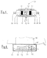
- Fig. 6 diagrammatically shows an example of the cross section of an activity detector 2 according to the invention as shown in Fig. 1.
- a printed circuit board 49 Arranged within the activity detector housing 48, attached to the cow's neck 47 for instance by means of a collar, is a printed circuit board 49 on which the electronics and, if necessary, a battery 50 are mounted, in addition to the movement sensor 51.
- the angle 52 at which sensor 51 is disposed, is chosen in accordance with the invention, such that the sensor extends horizontally at the average angle 10 of the heat movement 9 (see Fig. 1).
- this angle must be about 20 degrees to achieve maximum distinction between the heat movements and the eating movements.
- the space between housing 48 and the built-in components can be filled up with a setting encapsulating compound 53, so that the components are fixed and protected against moisture and other environmental influences.
- a metal sleeve which comprises a central ridge which constitutes an electrical connection.
- This connection can naturally be provided in different ways as well, for instance by providing an opening in an otherwise continuous insulating jacket 31, or, for instance, by providing an insulated connection in a longitudinal groove or bore in one of the plugs 36.
- balls instead of balls, other rolling or sliding elements, such as for instance rollers, can be used.
Landscapes
- Life Sciences & Earth Sciences (AREA)
- Health & Medical Sciences (AREA)
- Veterinary Medicine (AREA)
- Animal Husbandry (AREA)
- Biophysics (AREA)
- Environmental Sciences (AREA)
- Zoology (AREA)
- Wood Science & Technology (AREA)
- Engineering & Computer Science (AREA)
- Animal Behavior & Ethology (AREA)
- General Health & Medical Sciences (AREA)
- Public Health (AREA)
- Biodiversity & Conservation Biology (AREA)
- Pregnancy & Childbirth (AREA)
- Measurement Of The Respiration, Hearing Ability, Form, And Blood Characteristics Of Living Organisms (AREA)
- Geophysics And Detection Of Objects (AREA)
Claims (17)
- Verfahren zum Messen des Aktivitätsgrades eines Tieres (1) unter Verwendung einer in oder an dem Tier angebrachten Vorrichtung (2), mit einem Bewegungssensor (11; 21; 30; 44; 51) und einer elektronischen Zählschaltung, wobei ein Bewegungssensor (11; 21; 30; 44; 51) verwendet wird, dessen Empfindlichkeit von der Position des Bewegungssensors (11; 21; 30; 44; 51) abhängt, dadurch gekennzeichnet, daß festgestellt wird, welche Art von Bewegungen für die Meßzwecke bedeutend ist; daß der Bewegungssensor (11; 21; 30; 44; 51) derart in oder an dem Tier (1) angebracht wird, daß die höchste Empfindlichkeit des Bewegungssensors (11; 21; 30; 44; 51) in dem Raum (9) oder in einer Richtung gegeben ist, in der die für die Meßzwecke bedeutenden Bewegungen stattfinden.
- Verfahren nach Anspruch 1, dadurch gekennzeichnet, daß der Bewegungssensor (11; 21; 30; 44; 51) zum Erreichen der Selektivität für die relevante Bewegung des Tieres in bezug auf das Gesamtbewegungsmuster (6, 9) in der in oder an dem Tier (1) angebrachten Vorrichtung (2) derart angeordnet ist, daß der Bewegungssensor (11; 21; 30; 44; 51) die maximale Empfindlichkeit für die Bewegungsrichtung und/oder den Raumwinkel der relevanten Tierbewegungen (9) und die minimale Empfindlichkeit für die nicht relevanten Tierbewegungen (6) hat.
- Verfahren nach Anspruch 1 oder 2, bei dem der Meßzweck das Erkennen der Brunstperiode ist, dadurch gekennzeichnet, daß Nutzen aus der Erkenntnis gezogen wird, daß während der Brunst der Kopf und der Hals des Tiers (1) erheblich öfter nach oben geworfen werden als normal, wobei die Brunstbewegung durch ihren Raumwinkel (9) klar von der normalen Freßbewegung (6) unterscheidbar ist, bei der, im Gegensatz dazu, der Hals und der Kopf nach unten bewegt werden; daß die den Bewegungssensor (11; 21; 30; 44; 51) aufweisende Vorrichtung (2) am Hals des Tieres (1) angebracht wird und daß der positionsabhängige Bewegungssensor in der am Hals angebrachten Vorrichtung derart angeordnet wird, daß er während der Brunstbewegung empfindlich ist, während er während der Freßbewegung unempfindlich ist, so daß im wesentlichen die relevanten Brunstbewegungen gezählt werden und die Brunstperiode mit hoher Zuverlässigkeit anzeigen.
- Verfahren nach einem der vorhergehenden Ansprüche, dadurch gekennzeichnet, daß eine Vorrichtung (2) mit einem Bewegungssensor (11; 21; 30; 44; 51) verwendet wird, in der eine an sich bekannte drahtlos lesbare Identifizierungsschaltung eingebaut ist.
- Verfahren nach einem oder mehreren der vorhergehenden Ansprüche, dadurch gekennzeichnet, daß die Vorrichtung (2) im Körper des Tieres an einer für die Meßzwecke in bezug auf das Bewegungsmuster geeigneten Stelle angeordnet ist.
- Vorrichtung zum Messen des Aktivitätsgrades eines Tieres (1), mit einem Bewegungssensor (11; 21; 30; 44; 51) und einer elektronischen Zählschaltung, wobei der Bewegungssensor (11; 21; 30; 44; 51) von der Art ist, bei der die Empfindlichkeit von der räumlichen Position des Bewegungssensors (11; 21; 30; 44; 51) abhängt, dadurch gekennzeichnet, daß der Bewegungssensor (11; 21; 30; 44; 51) in der Vorrichtung (2) derart angebracht ist, daß er die empfindliche Position während Bewegungen (9) einnimmt, die für den Meßzweck relevant sind, und daß er die unempfindliche Position während anderen Bewegungen (6) einnimmt, wenn die Vorrichtung (2) an oder in dem Tier (1) vorgesehen ist.
- Vorrichtung nach Anspruch 6, dadurch gekennzeichnet, daß die Vorrichtung (2) ein Gehäuse (48) aufweist, das an einem Halsband (46) angebracht ist, um das Anbringen der Vorrichtung am Hals (47) eines Tieres zu ermöglichen.
- Vorrichtung nach Anspruch 6 oder 7, dadurch gekennzeichnet, daß die elektronische Zählschaltung drahtlos lesbar ist.
- Vorrichtung nach einem der Ansprüche 6-8, dadurch gekennzeichnet, daß die Vorrichtung (2) eine drahtlos lesbare elektronische Identifizierungsschaltung aufweist.
- Vorrichtung nach einem oder mehreren der Ansprüche 6-9, dadurch gekennzeichnet, daß der positionsabhängige Bewegungssensor (11; 21; 30; 44; 51) einen an einem Ende geschlossenen Rohrabschnitt (32), der am offenen Ende durch ein auf zwei Seiten mit einem Kontakimaterial (34, 35) versehenen Piezoelement (33), wobei in dem derart gebildeten Hohlraum (41) ein mit geringem Spiel rollendes Element (40) angeordnet ist, das bei korrekter Bewegungsrichtung des Sensors gegen das Piezoelement (33) stößt, wodurch wenigstens ein Teil der kinetischen Energie des rollenden Elements (40) in einen elektrischen Energieimpuls umgewandelt wird, der dem elektronischen Zähler der Vorrichtung (2) zugeführt wird.
- Verfahren nach einem der Ansprüche 6-9, dadurch gekennzeichnet, daß der positionsabhängige Bewegungssensor (11; 21; 30; 44; 51) einen Rohrabschnitt (45) aufweist, der an beiden Enden durch ein auf beiden Seiten mit Elektrodenmaterial versehenes Piezoelement (33) verschlossen ist, wobei in dem Rohrabschnitt ein rollendes Element (40) angeordnet ist, das je nach Position des Bewegungssensors zwischen den Piezoelementen (33) hin und her rollen kann.
- Vorrichtung nach Anspruch 10 oder 11, dadurch gekennzeichnet, daß das rollende Element (40) eine Kugel ist.
- Vorrichtung nach einem der Ansprüche 10-12, dadurch gekennzeichnet, daß der Rohrabschnitt (32; 45) ein metallischer Rohrabschnitt mit einer äußeren, elektrisch isolierenden Hülle (31) ist.
- Vorrichtung nach einem der Ansprüche 10-13, dadurch gekennzeichnet, daß der von einem Piezoelement (33) gelieferte Energieimpuls wenigstens teilweise einer Energiespeichereinrichtung zugeführt wird, welche eine elektrische Versorgungsquelle für zumindest die Zählschaltung bildet.
- Vorrichtung nach einem der Ansprüche 6-9, dadurch gekennzeichnet, daß der Bewegungssensor (11; 21; 30; 44; 51) einen an sich bekannten Quecksilbertropfensensor aufweist.
- Vorrichtung nach einem der Ansprüche 6-9, dadurch gekennzeichnet, daß der Bewegungssensor (11; 21; 30; 44; 51) ein an sich bekannter Kugelsensor ist.
- Vorrichtung nach einem oder mehreren der vorhergehenden Ansprüche, dadurch gekennzeichnet, daß die Längsachse des positionsabhängigen Sensors (11; 21; 30; 44; 51) in einem Winkel von ungefähr 20° relativ zu einer Platine (49) oder dergleichen angeordnet ist, aufder der Sensor (11; 21; 30; 44; 51) und andere elektronische Bauteile im Gehäuse (48) der Vorrichtung angebracht sind, wobei die Vorrichtung im Gebrauch derart am Hals (47) des Tieres (1) angebracht ist, daß sich die Platine (49) im wesentlichen parallel zur Halsoberfläche erstreckt.
Applications Claiming Priority (2)
| Application Number | Priority Date | Filing Date | Title |
|---|---|---|---|
| NL9401617 | 1994-10-03 | ||
| NL9401617A NL9401617A (nl) | 1994-10-03 | 1994-10-03 | Activiteitsdetector met standafhankelijke bewegingssensor. |
Publications (2)
| Publication Number | Publication Date |
|---|---|
| EP0705536A1 EP0705536A1 (de) | 1996-04-10 |
| EP0705536B1 true EP0705536B1 (de) | 1998-01-14 |
Family
ID=19864727
Family Applications (1)
| Application Number | Title | Priority Date | Filing Date |
|---|---|---|---|
| EP95202658A Expired - Lifetime EP0705536B1 (de) | 1994-10-03 | 1995-10-03 | Aktivitätsdetektor mit positionsabhängigem Bewegungssensor |
Country Status (4)
| Country | Link |
|---|---|
| EP (1) | EP0705536B1 (de) |
| DE (1) | DE69501446T2 (de) |
| IL (1) | IL115511A0 (de) |
| NL (1) | NL9401617A (de) |
Families Citing this family (19)
| Publication number | Priority date | Publication date | Assignee | Title |
|---|---|---|---|---|
| NL1002173C2 (nl) * | 1996-01-25 | 1997-07-29 | Maasland Nv | Werkwijze voor het automatisch melken van dieren. |
| FR2759541B1 (fr) * | 1997-02-18 | 1999-04-23 | Visio Systemes | Procede et installation de teledetection automatique de l'activite d'animaux en stabulation libre |
| EP0991315A1 (de) | 1997-07-02 | 2000-04-12 | Alfa Laval Agri Ab | Verfahren und vorrichtung zur überwachung eines tieres |
| FR2784889B1 (fr) | 1998-10-21 | 2001-02-16 | Instr Medecine Veterinaire | Dispositif pour detecter l'etat d'oestrus chez les vaches laitieres comprenant un support comportant un detecteur emettant des signaux lumineux enferme dans un boitier |
| NL1012872C2 (nl) * | 1999-08-20 | 2001-02-23 | Nedap Nv | Ligsensor voor dieren. |
| IL166394A0 (en) | 2005-01-19 | 2006-01-15 | Vladimir Voronin | A system and apparatus for detecting estrus |
| SE528838C2 (sv) * | 2005-04-29 | 2007-02-27 | Delaval Holding Ab | Detekteringsmetod jämte -arrangemang för mjölkboskap |
| NL1030464C2 (nl) * | 2005-11-18 | 2007-05-21 | Nedap Agri B V | Bewegingsdetector voor dieren. |
| IL173604A (en) | 2006-02-08 | 2013-01-31 | E Afikim Milking Systems Agricultural Cooperative Ltd Sa | A device and method for recording animal poses, especially for live animals |
| GB2437250C (en) | 2006-04-18 | 2012-08-15 | Iti Scotland Ltd | Method and system for monitoring the condition of livestock |
| EP2158483A1 (de) | 2007-05-31 | 2010-03-03 | S.A.E. Afikim | System und verfahren zur analyse von flüssigkeiten |
| WO2009011641A1 (en) * | 2007-07-13 | 2009-01-22 | Delaval Holding Ab | Method for detecting oestrus behaviour of a milking animal |
| GB0716333D0 (en) | 2007-08-22 | 2007-10-03 | White Spark Holdings Ltd | Method and apparatus for the automatic grading of condition of livestock |
| WO2013113297A1 (en) * | 2012-01-31 | 2013-08-08 | Univerzita Karlova V Praze | Electrode for percutaneous neurostimulation therapy and reflex movement detector |
| DE102016107624A1 (de) | 2016-03-22 | 2017-09-28 | Förster Technik GmbH | Verfahren zur Informationsanzeige an einem Tier und zum Auffinden eines Tieres |
| JP2019017267A (ja) * | 2017-07-12 | 2019-02-07 | デクセリアルズ株式会社 | 検出装置、検出システムおよび検出方法 |
| CN108522342B (zh) * | 2018-01-23 | 2020-09-11 | 北京师范大学 | 一种基于动作和叫声的动物行为监测、分析及预警系统及其工作方法 |
| WO2019180624A1 (en) | 2018-03-19 | 2019-09-26 | Halter USA Inc | Apparatus and method for controlling animal positions |
| CN109258508B (zh) * | 2018-09-26 | 2020-11-10 | 深圳市倍适沃智能设备有限公司 | 母猪发情分析方法、装置、终端与计算机可读存储介质 |
Family Cites Families (7)
| Publication number | Priority date | Publication date | Assignee | Title |
|---|---|---|---|---|
| US4051397A (en) * | 1975-08-08 | 1977-09-27 | Minnesota Mining And Manufacturing Company | Two sensitivity level kinetic sensor |
| US4234876A (en) * | 1976-10-19 | 1980-11-18 | Riken-Denshi Kogyo Kabushiki Kaisha | Omnidirectional move-stop sensor |
| GB1577920A (en) * | 1976-11-01 | 1980-10-29 | Nedap Nv | Detection plate for identification systems |
| US4247758A (en) * | 1979-11-15 | 1981-01-27 | Rodrian James A | Animal identification and estrus detection system |
| US4455610A (en) * | 1982-02-04 | 1984-06-19 | Rodrian James A | Self-contained estrous detection tag |
| US4618861A (en) * | 1985-03-20 | 1986-10-21 | Cornell Research Foundation, Inc. | Passive activity monitor for livestock |
| NL8901720A (nl) * | 1989-07-06 | 1991-02-01 | Nedap Nv | Voeding- en meetinrichting. |
-
1994
- 1994-10-03 NL NL9401617A patent/NL9401617A/nl not_active Application Discontinuation
-
1995
- 1995-10-03 EP EP95202658A patent/EP0705536B1/de not_active Expired - Lifetime
- 1995-10-03 DE DE69501446T patent/DE69501446T2/de not_active Expired - Lifetime
- 1995-10-03 IL IL11551195A patent/IL115511A0/xx unknown
Also Published As
| Publication number | Publication date |
|---|---|
| IL115511A0 (en) | 1996-01-19 |
| EP0705536A1 (de) | 1996-04-10 |
| NL9401617A (nl) | 1996-05-01 |
| DE69501446D1 (de) | 1998-02-19 |
| DE69501446T2 (de) | 1998-08-06 |
Similar Documents
| Publication | Publication Date | Title |
|---|---|---|
| EP0705536B1 (de) | Aktivitätsdetektor mit positionsabhängigem Bewegungssensor | |
| EP1874111B1 (de) | Erfassungsverfahren und anordnung für milchvieh | |
| US20230404060A1 (en) | Sensor for a wireless animal trap detection system | |
| US4618861A (en) | Passive activity monitor for livestock | |
| EP3739299B1 (de) | Detektion von objekten | |
| CA2785925C (en) | Device for the measurement of individual farm animal data | |
| EP2496075A1 (de) | Verfahren und system zur messung der mobilität eines tieres | |
| CN107072186A (zh) | 有害生物控制系统及其操作方法 | |
| DE69902660D1 (de) | Feuchtigkeitssensor | |
| EP2457102A1 (de) | Verfahren zur bestimmung der bewegungen eines tieres | |
| NL8901165A (nl) | Mastitis sensor. | |
| US10872515B2 (en) | Method and apparatus for monitoring and reporting salt level in a water softener | |
| NL1012872C2 (nl) | Ligsensor voor dieren. | |
| KR100941498B1 (ko) | 맥박 측정용 압력센서를 이용한 가축 질병관리장치 | |
| WO2023031759A1 (en) | Animal husbandry system | |
| WO2024213388A1 (de) | Hufschutz, vorzugsweise hufschuh oder hufglocke | |
| Harty | Automating heat detection | |
| WO2025144060A1 (en) | A system for monitoring animal migration | |
| JPS6015125Y2 (ja) | 実験動物運動量測定装置 | |
| WO2025144059A1 (en) | A monitoring station for animal migration | |
| ITMI970721A1 (it) | Dispositivo di localizzazione di capezzoli per apparati di mungitura automatizzata |
Legal Events
| Date | Code | Title | Description |
|---|---|---|---|
| PUAI | Public reference made under article 153(3) epc to a published international application that has entered the european phase |
Free format text: ORIGINAL CODE: 0009012 |
|
| AK | Designated contracting states |
Kind code of ref document: A1 Designated state(s): DE FR GB NL SE |
|
| 17P | Request for examination filed |
Effective date: 19960702 |
|
| 17Q | First examination report despatched |
Effective date: 19960807 |
|
| GRAG | Despatch of communication of intention to grant |
Free format text: ORIGINAL CODE: EPIDOS AGRA |
|
| GRAG | Despatch of communication of intention to grant |
Free format text: ORIGINAL CODE: EPIDOS AGRA |
|
| GRAH | Despatch of communication of intention to grant a patent |
Free format text: ORIGINAL CODE: EPIDOS IGRA |
|
| GRAH | Despatch of communication of intention to grant a patent |
Free format text: ORIGINAL CODE: EPIDOS IGRA |
|
| GRAA | (expected) grant |
Free format text: ORIGINAL CODE: 0009210 |
|
| AK | Designated contracting states |
Kind code of ref document: B1 Designated state(s): DE FR GB NL SE |
|
| REF | Corresponds to: |
Ref document number: 69501446 Country of ref document: DE Date of ref document: 19980219 |
|
| ET | Fr: translation filed | ||
| PG25 | Lapsed in a contracting state [announced via postgrant information from national office to epo] |
Ref country code: SE Free format text: LAPSE BECAUSE OF FAILURE TO SUBMIT A TRANSLATION OF THE DESCRIPTION OR TO PAY THE FEE WITHIN THE PRESCRIBED TIME-LIMIT Effective date: 19980414 |
|
| PLBE | No opposition filed within time limit |
Free format text: ORIGINAL CODE: 0009261 |
|
| STAA | Information on the status of an ep patent application or granted ep patent |
Free format text: STATUS: NO OPPOSITION FILED WITHIN TIME LIMIT |
|
| 26N | No opposition filed | ||
| REG | Reference to a national code |
Ref country code: GB Ref legal event code: IF02 |
|
| PGFP | Annual fee paid to national office [announced via postgrant information from national office to epo] |
Ref country code: DE Payment date: 20121023 Year of fee payment: 18 Ref country code: FR Payment date: 20121031 Year of fee payment: 18 |
|
| PGFP | Annual fee paid to national office [announced via postgrant information from national office to epo] |
Ref country code: GB Payment date: 20121019 Year of fee payment: 18 |
|
| PGFP | Annual fee paid to national office [announced via postgrant information from national office to epo] |
Ref country code: NL Payment date: 20121015 Year of fee payment: 18 |
|
| REG | Reference to a national code |
Ref country code: NL Ref legal event code: V1 Effective date: 20140501 |
|
| GBPC | Gb: european patent ceased through non-payment of renewal fee |
Effective date: 20131003 |
|
| REG | Reference to a national code |
Ref country code: DE Ref legal event code: R119 Ref document number: 69501446 Country of ref document: DE Effective date: 20140501 |
|
| PG25 | Lapsed in a contracting state [announced via postgrant information from national office to epo] |
Ref country code: GB Free format text: LAPSE BECAUSE OF NON-PAYMENT OF DUE FEES Effective date: 20131003 |
|
| REG | Reference to a national code |
Ref country code: FR Ref legal event code: ST Effective date: 20140630 |
|
| PG25 | Lapsed in a contracting state [announced via postgrant information from national office to epo] |
Ref country code: FR Free format text: LAPSE BECAUSE OF NON-PAYMENT OF DUE FEES Effective date: 20131031 Ref country code: NL Free format text: LAPSE BECAUSE OF NON-PAYMENT OF DUE FEES Effective date: 20140501 Ref country code: DE Free format text: LAPSE BECAUSE OF NON-PAYMENT OF DUE FEES Effective date: 20140501 |