EP0705554B1 - Fritiergerät - Google Patents
Fritiergerät Download PDFInfo
- Publication number
- EP0705554B1 EP0705554B1 EP19950307097 EP95307097A EP0705554B1 EP 0705554 B1 EP0705554 B1 EP 0705554B1 EP 19950307097 EP19950307097 EP 19950307097 EP 95307097 A EP95307097 A EP 95307097A EP 0705554 B1 EP0705554 B1 EP 0705554B1
- Authority
- EP
- European Patent Office
- Prior art keywords
- module
- thermostat
- housing
- deep fryer
- control
- Prior art date
- Legal status (The legal status is an assumption and is not a legal conclusion. Google has not performed a legal analysis and makes no representation as to the accuracy of the status listed.)
- Expired - Lifetime
Links
- 238000010438 heat treatment Methods 0.000 claims description 6
- XLYOFNOQVPJJNP-UHFFFAOYSA-N water Substances O XLYOFNOQVPJJNP-UHFFFAOYSA-N 0.000 description 2
- 238000004140 cleaning Methods 0.000 description 1
- 230000000295 complement effect Effects 0.000 description 1
- 238000010411 cooking Methods 0.000 description 1
- 238000010586 diagram Methods 0.000 description 1
- 238000007654 immersion Methods 0.000 description 1
- 230000004048 modification Effects 0.000 description 1
- 238000012986 modification Methods 0.000 description 1
- 238000000465 moulding Methods 0.000 description 1
- 230000007935 neutral effect Effects 0.000 description 1
- 230000000717 retained effect Effects 0.000 description 1
- 239000000523 sample Substances 0.000 description 1
Images




Classifications
-
- A—HUMAN NECESSITIES
- A47—FURNITURE; DOMESTIC ARTICLES OR APPLIANCES; COFFEE MILLS; SPICE MILLS; SUCTION CLEANERS IN GENERAL
- A47J—KITCHEN EQUIPMENT; COFFEE MILLS; SPICE MILLS; APPARATUS FOR MAKING BEVERAGES
- A47J37/00—Baking; Roasting; Grilling; Frying
- A47J37/12—Deep fat fryers, e.g. for frying fish or chips
- A47J37/1266—Control devices, e.g. to control temperature, level or quality of the frying liquid
-
- G—PHYSICS
- G05—CONTROLLING; REGULATING
- G05D—SYSTEMS FOR CONTROLLING OR REGULATING NON-ELECTRIC VARIABLES
- G05D23/00—Control of temperature
- G05D23/19—Control of temperature characterised by the use of electric means
- G05D23/1919—Control of temperature characterised by the use of electric means characterised by the type of controller
-
- H—ELECTRICITY
- H01—ELECTRIC ELEMENTS
- H01H—ELECTRIC SWITCHES; RELAYS; SELECTORS; EMERGENCY PROTECTIVE DEVICES
- H01H37/00—Thermally-actuated switches
- H01H37/02—Details
- H01H37/04—Bases; Housings; Mountings
- H01H37/06—Bases; Housings; Mountings to facilitate replacement, e.g. cartridge housing
Definitions
- This invention relates to deep fryers particularly for domestic use, such as for frying chips or other types of food.
- GB 2255002B describes a deep fryer having a detachable electric plug comprising a thermostatic control and having a temperature detecting probe which may be inserted into a cavity or recess of a housing of the deep fryer.
- the plug also serves to connect a power supply between electrical contacts of a heating element associated with the bowl or container of the fryer which receives the food to be fried.
- the plug is removed, the remaining components of the fryer can be washed by immersion in water.
- the connection of the plug to components of the fryer can be somewhat unsatisfactory and the plug may even be dislodged accidentally.
- the invention consists in a deep fryer comprising an outer housing closable by a lid, a container for containing oil and a basket for retaining food to be fried, the container being located in the housing and the basket being removably placed in the container, a heating element enclosed in a watertight casing carried by or forming a compartment in said container and having electrical contacts extending externally of said casing in a watertight manner, and means for connecting an electrical supply to said contacts via cooperating contacts carried by a module locatable in an aperture in said housing, characterised in that said module carries a manually controllable thermostat for setting the temperature to which oil may be heated in the container and releasable locking means for locking the module in its located position in said aperture.
- the releasable locking means are such that when they are unlocked to allow the module to be withdrawn from the aperture, the thermostat cannot be set.
- the manual control for the thermostat also controls the operation of the locking means. This may be achieved by means of a thermostat control which can be moved from a reference position in one direction to adjust the setting of the thermostat and in another direction to control the locking means.
- the thermostat control is a rotatable control.
- the locking means may comprise one or more spring loaded latches which engage with the housing when the module is positioned in the aperture. Movement, e.g. rotation, of the thermostat control to the unlocking position withdraws the or each latch against the action of its spring and thereby allows a spring loaded shutter to be actuated to retain the latch in its unlocked position and so prevent movement of the thermostat control.
- the actuation of the spring loaded shutter may also serve to urge the module out of its aperture and facilitate its total withdrawal from the housing.
- the deep fryer 1 is generally rectangular in plan and comprises a container 2 accommodated within an outer housing 3 having a lid 4, and a wire basket 5 which fits within the container.
- the basket has a handle 5 a which is pivotally connected to the basket and which is adapted to lie adjacent the side of the housing 3 when the basket is located in the housing. Raising of the handle 5 a to a generally horizontal position causes the lid 4 to be opened so that the basket can be removed.
- GB-2 241 160B Such an arrangement is disclosed in GB-2 241 160B.
- the front of the housing 3 is provided with an opening 10 in which can be located a control module 9 as will hereinafter be described.
- a heating element 6 sealed within a casing 7 is mounted on the underside of the container 2 such that the encased heating element is in thermal contact with the container.
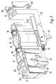
- the element 6 has watertight electrical contacts 8 which extend from the casing 7 and which engage with complementary contacts 36 on the control module 9, when it is inserted into the opening 10 in the housing 3, as shown in more detail in Figures 3 to 8.
- the module 9 comprises a rectangular housing 11, a base 12 and a rear panel 13. For convenience, these parts are not shown in Figure 3.
- a rotary knob 14 located on the front of the housing 11 is connected through an aperture in the housing 11 to a thermostat actuator 15.
- the actuator is in turn connected to a thermostat 16, which, together with a thermal cut-off 17, is housed within a thermostat housing 18.
- Two contacts 19 are connected through apertures in flanges of the thermostat and the thermal cut-off to respective thermal sliders 20, which are slidably located between these compartments and the front surface of the thermostat housing 18.
- the ends of the contacts 19 extend through apertures in the rear panel 13 and have flanges 22 which are biassed by the springs 21 against the inside of the panel.
- Two generally L-shaped latch members 23 are mounted so as to be laterally slidable in the module housing 11 adjacent the thermostat housing 18.
- the latch members are biassed outwardly against the module housing by springs 24 and have camming surfaces 25 which engage cams 26 on the thermostat actuator 15.
- the latch members 23 each have a rectangular latch 27 extending outwardly from the shorter limb of the L.
- two shutters 28 are mounted so as to slide along recessed rectangular slideways 29 in the sides of the module housing 11.
- Springs 30 bias the shutters rearwardly, acting against the front of the module housing.
- the shutters 28 each have a rectangular aperture 31 large enough to admit the latch 27, and the slideways 29 also each have an aperture 32 of the same size, as well as a front aperture 33.
- the module 9 is inserted into the opening 10 of the deep fryer housing 3 with the knob 14 in the position shown in Figure 7. In this position, the latch members 23 are held retracted by the shutters 28 since the latter are in their rearward position where the apertures 31 are not in line with the latches 27 and the front edges of the shutters extend through the apertures 33.
- a front latch block 34 and a rear latch block 35 are arranged on either side within the opening 10.
- the front latch blocks come into contact with the front edges of the shutters 28 and urge them forwards, relative to the module 9, against the action of the springs 30, until the latches 27 are aligned with the apertures 31.
- the springs 24 urge the latch members 23 outwards and the latches 27 extend through the apertures 31, 32 and each engage in the gap between the latching blocks 34, 35, thus locking the module in place.
- the cams 26 move relative to the surfaces 25 on the thermostat actuator 10, thereby enabling the knob 15 to be rotated to set the thermostat 16, through the actuator 15.
- the rear panel 13 has live, neutral and earth sockets 36 which are engaged by the respective contacts 8 of the element 6 when the module is fully inserted.
- the element is connected to a power supply (not shown) via the thermostat 16 and a mains cord extending through an outlet 37.
- the contacts 19 are retained against the wall of the container 2 by the pressure of the springs 21.
- the thermostat can now be set to a desired cooking temperature by turning the knob 14 in a clockwise direction.
- the knob 14 In order to remove the module 9, the knob 14 must first be returned to a "zero" position in which the electrical power is cut off. The knob is then turned further anticlockwise, which withdraws the latches 27 by the action of the cams 26 on the camming surfaces 25. The shutters 28 are then urged to their rearward position by the springs 30, which also tend to eject the module 9 as the front edges of the shutters are urged away from the latch blocks 34.
- the knob 14 cannot be turned clockwise, since the shutters 28 prevent outward movement of the latch members 23 and hence rotation of the cams 26. Thus the power cannot be switched on, so preventing a potential safety hazard.
- the container 2, housing 3, lid 4 and basket 5 can then be disassembled and immersed in water safely for cleaning purposes.
- the invention as described, provides a deep fryer having a convenient and safe control module which locks in place in the housing.
- the locking mechanism and the thermostat could be controlled by separate means rather than both by the knob 14, in which case the two separate controls are preferably arranged to interlock.
- a moulding 40 on the shutters 28 may be provided to operate a micro-switch 41 so that when the shutters 28 spring closed the micro-switch contacts are opened to prevent power to the thermostat 16 and heating element 6 unless the module is locked in the correct position.
- the specific embodiment shows a rectangular shaped fryer, other shapes of fryer such as a square or round shape may be used.
- the thermostat control can be any suitable type of thermostatic device, such as a bimetallic or electronic device.
Landscapes
- Engineering & Computer Science (AREA)
- Food Science & Technology (AREA)
- Physics & Mathematics (AREA)
- General Physics & Mathematics (AREA)
- Automation & Control Theory (AREA)
- Frying-Pans Or Fryers (AREA)
Claims (8)
- Fritiergerät (1) umfassend ein mit einem Deckel (4) verschließbares äußeres Gehäuse (3), einen Behälter (2) zur Aufnahme von Öl und einen Korb (5) zur Aufnahme zu fritierender Nahrungsmittel, wobei der Behälter (2) in dem Gehäuse (3) angeordnet ist und der Korb (5) herausnehmbar in den Behälter (2) eingesetzt ist, ein Heizelement (6), das von einem wasserdichten Gehäuse (7) umschlossen und von einem abgeteilten Fach in dem Behälter (2) getragen wird oder ein solches Fach bildet und elektrische Kontakte (8) besitzt, die sich wasserdicht abgeschlossen außerhalb des Gehäuses (7) erstrecken, und Mittel zum Anschluß einer elektrischen Energieversorgung an die Kontakte (8) über mit diesen zusammenwirkende Kontakte (36), die von einem Modul (9) getragen werden, welches in eine Öffnung (10) in dem Gehäuse (3) eingesetzt werden kann, dadurch gekennzeichnet, daß das Modul (9) einen von Hand regelbaren Thermostaten (16) zum Einstellen der Temperatur besitzt; auf die im Behälter (2) befindliches Öl erhitzt werden soll, und lösbare Verriegelungsmittel (23, 27) zum Verriegeln des Moduls (9) in seiner eingesetzten Position in der Öffnung (10).
- Fritiergerät nach Anspruch 1, bei dem die lösbaren Verriegelungsmittel (23, 27) so angeordnet sind, daß der Thermostat (16) nicht verstellt werden kann, wenn die Verriegelungsmittel geöffnet sind, um das Herausziehen des Moduls (9) aus der Öffnung (10) zu gestatten.
- Fritiergerät nach Anspruch 1 oder 2, bei dem der handbedienbare Einsteller (14) für den Thermostaten (16) auch zur Steuerung der Verriegelungsmittel (23, 27) dient.
- Fritiergerät nach Anspruch 3, bei dem der Einsteller (14) so ausgebildet ist, daß er zum Neueinstellen des Thermostaten (16) ausgehend von einer Bezugsposition in eine Richtung bewegt werden kann, und zum Steuern der Verriegelungsmittel (23, 27) in eine andere Richtung.
- Fritiergerät nach einem der vorstehenden Ansprüche, bei dem der Thermostateinsteller (14) aus einem drehbaren Einsteller (14) besteht.
- Fritiergerät nach einem der vorstehenden Ansprüche, bei dem die Verriegelungsmittel (23, 27) eine oder mehrere federbelastete Einschnappklinken (27) enthalten, die mit dem Gehäuse (3) zum Eingriff kommen, wenn das Modul (9) in die Öffnung (10) eingesetzt wird.
- Fritiergerät nach Anspruch 6, bei den das Modul (9) einen federbelasteten Verschlußmechanismus (28) umfaßt, der so ausgebildet ist, daß er die oder jede der Verschlußklinke(n) (27) zurückhält und die Bewegung des Thermostateinstellers (14) verhindert, wenn sich die Verriegelungsmittel (23, 27) in ihrer unverriegelten Stellung befinden.
- Fritiergerät nach Anspruch 7, bei dem die Betätigung des oder jedes der federbelasteten Verschlußmechanismus(men) (28) zum Zurückhalten der Einschnappklinke (27) auch dazu dient, das Modul (9) aus seiner Öffnung (10) herauszudrücken und so seine völligen Herausnahme aus dem Gehäuse (3) erleichtert.
Applications Claiming Priority (2)
| Application Number | Priority Date | Filing Date | Title |
|---|---|---|---|
| GB9420187A GB2293755B (en) | 1994-10-06 | 1994-10-06 | Deep fryers |
| GB9420187 | 1994-10-06 |
Publications (2)
| Publication Number | Publication Date |
|---|---|
| EP0705554A1 EP0705554A1 (de) | 1996-04-10 |
| EP0705554B1 true EP0705554B1 (de) | 1999-04-28 |
Family
ID=10762457
Family Applications (1)
| Application Number | Title | Priority Date | Filing Date |
|---|---|---|---|
| EP19950307097 Expired - Lifetime EP0705554B1 (de) | 1994-10-06 | 1995-10-06 | Fritiergerät |
Country Status (3)
| Country | Link |
|---|---|
| EP (1) | EP0705554B1 (de) |
| DE (1) | DE69509330T2 (de) |
| GB (1) | GB2293755B (de) |
Families Citing this family (10)
| Publication number | Priority date | Publication date | Assignee | Title |
|---|---|---|---|---|
| GB9701039D0 (en) * | 1997-01-18 | 1997-03-05 | Kenwood Marks Ltd | Electrically-heated appliance |
| DE19714038B4 (de) * | 1997-04-04 | 2006-04-13 | 3Rd Angle (U.K.) Ltd., Highley | Elektro-Friteuse |
| GB2354427A (en) * | 1999-09-16 | 2001-03-28 | Eastern Sources Housewares | Electric cooking apparatus |
| GB2365757B (en) * | 2000-06-08 | 2002-07-31 | Dongming Wang | Electric fryer |
| US6759634B2 (en) * | 2001-09-11 | 2004-07-06 | Donglei Wang | Electric fryer |
| FR2858535B1 (fr) * | 2003-08-05 | 2007-06-22 | Seb Sa | Appareil electrique de cuisson comportant un socle d'alimentation electrique |
| FR2858537B1 (fr) * | 2003-08-05 | 2007-02-23 | Seb Sa | Appareil electrique de cuisson comportant un socle de vidange |
| EP1772086A1 (de) * | 2005-10-08 | 2007-04-11 | Electrical Investments Limited | Beheiztes Gerät mit herausnehmbarem Behälter mit intergrierten thermischen Sensoren |
| GB2437914A (en) * | 2006-05-11 | 2007-11-14 | Ya Horng Electronic Co Ltd | Cooker which locks to electrical supply base |
| FR2901463A1 (fr) * | 2006-05-23 | 2007-11-30 | Ya Horng Electronic Co Ltd | Dispositif de cuisson |
Family Cites Families (4)
| Publication number | Priority date | Publication date | Assignee | Title |
|---|---|---|---|---|
| BE1001974A5 (fr) * | 1988-05-17 | 1990-05-02 | Itt Ind Belgium | Appareil de cuisson d'aliments. |
| GB2255002B (en) * | 1990-01-29 | 1993-12-15 | Kenwood Marks Ltd | Deep fryers |
| GB9001973D0 (en) * | 1990-01-29 | 1990-03-28 | Kenwood Marks Ltd | Deep fat fryers |
| GB9217090D0 (en) * | 1992-08-12 | 1992-09-23 | Morphy Ltd Richards | Fryers |
-
1994
- 1994-10-06 GB GB9420187A patent/GB2293755B/en not_active Revoked
-
1995
- 1995-10-06 EP EP19950307097 patent/EP0705554B1/de not_active Expired - Lifetime
- 1995-10-06 DE DE1995609330 patent/DE69509330T2/de not_active Expired - Fee Related
Also Published As
| Publication number | Publication date |
|---|---|
| GB2293755B (en) | 1998-09-02 |
| GB9420187D0 (en) | 1994-11-23 |
| EP0705554A1 (de) | 1996-04-10 |
| DE69509330D1 (de) | 1999-06-02 |
| GB2293755A (en) | 1996-04-10 |
| DE69509330T2 (de) | 1999-12-16 |
Similar Documents
| Publication | Publication Date | Title |
|---|---|---|
| EP0705554B1 (de) | Fritiergerät | |
| US6742444B1 (en) | Electric cooking apparatus | |
| US6006658A (en) | Electrical deep fryer | |
| US5451745A (en) | Toy oven | |
| US20050247210A1 (en) | Electric cooking apparatus having removable heating plates and method for using same | |
| US5496987A (en) | Electric oven, for domestic use, particularly designed to cooking pizzas, cakes and the like | |
| US4173179A (en) | Cooking assembly | |
| EP1195122B1 (de) | Fritiergerät und Verfahren | |
| CN118266778A (zh) | 空气油炸烹饪器具 | |
| GB2255002A (en) | Deep fryers | |
| CN100569161C (zh) | 包括两个通过铰链连接的加热组件的家用电器设备 | |
| CN211324495U (zh) | 烹饪器具 | |
| CN217937956U (zh) | 一种多用途电热烹饪器具 | |
| EP3912531A1 (de) | Heissluftkochgerät mit einer vorrichtung zur beheizung eines gefässes durch wärmeleitung | |
| US3056013A (en) | Cooking appliance | |
| CN215937112U (zh) | 一种分体式烤箱 | |
| CN113413076A (zh) | 一种分体式烤箱 | |
| GB2241160A (en) | Deep fryers | |
| US4242570A (en) | Electric skillet having removably attachable handle | |
| US4307658A (en) | Apparatus for releasably retaining cooking griddles in a cooking appliance | |
| ES2263837T3 (es) | Horno microondas con tostador de pan. | |
| CN218304554U (zh) | 一种食物烹饪装置 | |
| CN219699606U (zh) | 一种多烹饪方式锅具 | |
| CN113558492A (zh) | 一种多用途电热烹饪器具 | |
| JP6647671B2 (ja) | ホットプレート |
Legal Events
| Date | Code | Title | Description |
|---|---|---|---|
| PUAI | Public reference made under article 153(3) epc to a published international application that has entered the european phase |
Free format text: ORIGINAL CODE: 0009012 |
|
| AK | Designated contracting states |
Kind code of ref document: A1 Designated state(s): CH DE ES FR GB IT LI NL PT SE |
|
| 17P | Request for examination filed |
Effective date: 19960716 |
|
| GRAG | Despatch of communication of intention to grant |
Free format text: ORIGINAL CODE: EPIDOS AGRA |
|
| 17Q | First examination report despatched |
Effective date: 19971020 |
|
| GRAG | Despatch of communication of intention to grant |
Free format text: ORIGINAL CODE: EPIDOS AGRA |
|
| GRAH | Despatch of communication of intention to grant a patent |
Free format text: ORIGINAL CODE: EPIDOS IGRA |
|
| GRAH | Despatch of communication of intention to grant a patent |
Free format text: ORIGINAL CODE: EPIDOS IGRA |
|
| GRAA | (expected) grant |
Free format text: ORIGINAL CODE: 0009210 |
|
| AK | Designated contracting states |
Kind code of ref document: B1 Designated state(s): CH DE ES FR GB IT LI NL PT SE |
|
| PG25 | Lapsed in a contracting state [announced via postgrant information from national office to epo] |
Ref country code: SE Free format text: THE PATENT HAS BEEN ANNULLED BY A DECISION OF A NATIONAL AUTHORITY Effective date: 19990428 Ref country code: LI Free format text: LAPSE BECAUSE OF FAILURE TO SUBMIT A TRANSLATION OF THE DESCRIPTION OR TO PAY THE FEE WITHIN THE PRESCRIBED TIME-LIMIT Effective date: 19990428 Ref country code: IT Free format text: LAPSE BECAUSE OF FAILURE TO SUBMIT A TRANSLATION OF THE DESCRIPTION OR TO PAY THE FEE WITHIN THE PRE;WARNING: LAPSES OF ITALIAN PATENTS WITH EFFECTIVE DATE BEFORE 2007 MAY HAVE OCCURRED AT ANY TIME BEFORE 2007. THE CORRECT EFFECTIVE DATE MAY BE DIFFERENT FROM THE ONE RECORDED.SCRIBED TIME-LIMIT Effective date: 19990428 Ref country code: ES Free format text: THE PATENT HAS BEEN ANNULLED BY A DECISION OF A NATIONAL AUTHORITY Effective date: 19990428 Ref country code: CH Free format text: LAPSE BECAUSE OF FAILURE TO SUBMIT A TRANSLATION OF THE DESCRIPTION OR TO PAY THE FEE WITHIN THE PRESCRIBED TIME-LIMIT Effective date: 19990428 |
|
| REG | Reference to a national code |
Ref country code: CH Ref legal event code: EP |
|
| REF | Corresponds to: |
Ref document number: 69509330 Country of ref document: DE Date of ref document: 19990602 |
|
| ET | Fr: translation filed | ||
| PG25 | Lapsed in a contracting state [announced via postgrant information from national office to epo] |
Ref country code: PT Free format text: LAPSE BECAUSE OF FAILURE TO SUBMIT A TRANSLATION OF THE DESCRIPTION OR TO PAY THE FEE WITHIN THE PRESCRIBED TIME-LIMIT Effective date: 19990729 |
|
| PGFP | Annual fee paid to national office [announced via postgrant information from national office to epo] |
Ref country code: NL Payment date: 19991029 Year of fee payment: 5 |
|
| REG | Reference to a national code |
Ref country code: CH Ref legal event code: PL |
|
| PLBE | No opposition filed within time limit |
Free format text: ORIGINAL CODE: 0009261 |
|
| STAA | Information on the status of an ep patent application or granted ep patent |
Free format text: STATUS: NO OPPOSITION FILED WITHIN TIME LIMIT |
|
| 26N | No opposition filed | ||
| PG25 | Lapsed in a contracting state [announced via postgrant information from national office to epo] |
Ref country code: NL Free format text: LAPSE BECAUSE OF NON-PAYMENT OF DUE FEES Effective date: 20010501 |
|
| NLV4 | Nl: lapsed or anulled due to non-payment of the annual fee |
Effective date: 20010501 |
|
| REG | Reference to a national code |
Ref country code: GB Ref legal event code: IF02 |
|
| PGFP | Annual fee paid to national office [announced via postgrant information from national office to epo] |
Ref country code: GB Payment date: 20060922 Year of fee payment: 12 |
|
| PGFP | Annual fee paid to national office [announced via postgrant information from national office to epo] |
Ref country code: DE Payment date: 20061025 Year of fee payment: 12 |
|
| REG | Reference to a national code |
Ref country code: GB Ref legal event code: 732E |
|
| REG | Reference to a national code |
Ref country code: FR Ref legal event code: TP |
|
| GBPC | Gb: european patent ceased through non-payment of renewal fee |
Effective date: 20071006 |
|
| PG25 | Lapsed in a contracting state [announced via postgrant information from national office to epo] |
Ref country code: DE Free format text: LAPSE BECAUSE OF NON-PAYMENT OF DUE FEES Effective date: 20080501 |
|
| REG | Reference to a national code |
Ref country code: FR Ref legal event code: ST Effective date: 20080630 |
|
| PGFP | Annual fee paid to national office [announced via postgrant information from national office to epo] |
Ref country code: FR Payment date: 20061002 Year of fee payment: 12 |
|
| PG25 | Lapsed in a contracting state [announced via postgrant information from national office to epo] |
Ref country code: GB Free format text: LAPSE BECAUSE OF NON-PAYMENT OF DUE FEES Effective date: 20071006 |
|
| PG25 | Lapsed in a contracting state [announced via postgrant information from national office to epo] |
Ref country code: FR Free format text: LAPSE BECAUSE OF NON-PAYMENT OF DUE FEES Effective date: 20071031 |