EP0705664A1 - Pneumatisch betätigtes Eintreibgerät für Befestigungsmittel - Google Patents
Pneumatisch betätigtes Eintreibgerät für Befestigungsmittel Download PDFInfo
- Publication number
- EP0705664A1 EP0705664A1 EP95306808A EP95306808A EP0705664A1 EP 0705664 A1 EP0705664 A1 EP 0705664A1 EP 95306808 A EP95306808 A EP 95306808A EP 95306808 A EP95306808 A EP 95306808A EP 0705664 A1 EP0705664 A1 EP 0705664A1
- Authority
- EP
- European Patent Office
- Prior art keywords
- valve member
- housing structure
- annular
- cylindrical wall
- facing
- Prior art date
- Legal status (The legal status is an assumption and is not a legal conclusion. Google has not performed a legal analysis and makes no representation as to the accuracy of the status listed.)
- Withdrawn
Links
- 239000000463 material Substances 0.000 claims description 6
- 229910000838 Al alloy Inorganic materials 0.000 claims description 4
- 229910000861 Mg alloy Inorganic materials 0.000 claims description 3
- XAGFODPZIPBFFR-UHFFFAOYSA-N aluminium Chemical compound [Al] XAGFODPZIPBFFR-UHFFFAOYSA-N 0.000 claims description 3
- 238000007789 sealing Methods 0.000 abstract description 42
- 239000003570 air Substances 0.000 description 7
- 150000002825 nitriles Chemical class 0.000 description 6
- 125000000218 acetic acid group Chemical group C(C)(=O)* 0.000 description 3
- 230000007797 corrosion Effects 0.000 description 3
- 238000005260 corrosion Methods 0.000 description 3
- 229920000642 polymer Polymers 0.000 description 3
- 229920002292 Nylon 6 Polymers 0.000 description 2
- 239000012080 ambient air Substances 0.000 description 2
- 229910052751 metal Inorganic materials 0.000 description 2
- 239000002184 metal Substances 0.000 description 2
- 229910000831 Steel Inorganic materials 0.000 description 1
- 230000001133 acceleration Effects 0.000 description 1
- 150000002739 metals Chemical class 0.000 description 1
- 239000002245 particle Substances 0.000 description 1
- 229920002635 polyurethane Polymers 0.000 description 1
- 239000004814 polyurethane Substances 0.000 description 1
- 239000010959 steel Substances 0.000 description 1
Images


Classifications
-
- B—PERFORMING OPERATIONS; TRANSPORTING
- B25—HAND TOOLS; PORTABLE POWER-DRIVEN TOOLS; MANIPULATORS
- B25C—HAND-HELD NAILING OR STAPLING TOOLS; MANUALLY OPERATED PORTABLE STAPLING TOOLS
- B25C1/00—Hand-held nailing tools; Nail feeding devices
- B25C1/04—Hand-held nailing tools; Nail feeding devices operated by fluid pressure, e.g. by air pressure
- B25C1/041—Hand-held nailing tools; Nail feeding devices operated by fluid pressure, e.g. by air pressure with fixed main cylinder
- B25C1/042—Main valve and main cylinder
-
- B—PERFORMING OPERATIONS; TRANSPORTING
- B25—HAND TOOLS; PORTABLE POWER-DRIVEN TOOLS; MANIPULATORS
- B25D—PERCUSSIVE TOOLS
- B25D9/00—Portable percussive tools with fluid-pressure drive, i.e. driven directly by fluids, e.g. having several percussive tool bits operated simultaneously
Definitions
- This invention pertains generally to an improved, pneumatically powered, fastener-driving tool, such as a nail-driving tool or a staple-driving tool, of a type having a valve member for controlling a driving piston.
- Pneumatically powered, fastener-driving tools of the type noted above are available commercially from ITW Paslode (a unit of Illinois Tool Works Inc.) of Lincolnshire, Illinois, under the PASLODE trademark.
- PASLODE 5300C Series Nailers exemplify those tools.
- a coil spring is used to bias a valve piston in one axial direction and to permit the valve piston to be axially moved in an opposite direction.
- O-rings are used to provide seals between the valve piston and the housing structure.
- the coil spring is made from steel
- the valve piston is made from a polymeric material, such as nylon 6/6
- the housing structure and other co-acting elements including an upper cap, against which the coil spring bears are made from another metal, such as an aluminum or magnesium alloy. Therefore, galvanic corrosion tends to occur between the coil spring and the housing structure, particularly at the upper cap. Galvanic corrosion tends to produce oxide particles, which tend to abrade the O-rings.
- high acceleration is imparted to the coil spring, which tends to be readily broken so as to damage the upper cap. Consequently, the coil spring, the upper cap, and the O-rings must be frequently replaced to maintain such a tool in prime operating condition.
- a pneumatically driven, fastener-driving tool comprises:
- An improved tool according to this invention does not employ a coil spring to bias a valve member, such as a valve piston, in one axial direction and to permit the valve member to be axially moved in an opposite direction, as discussed above. Rather, it uses an elastomeric member, which does not engender galvanic corrosion and which also functions as a bumper between the valve member and the housing structure. Functioning as a bumper between the valve member and the upper portion of the housing structure when the valve member is moved upwardly, the elastomeric member performs an additional function that the coil spring discussed above does not perform adequately.
- the upper portion of the housing structure has an radially inwardly facing, cylindrical wall facing the upper chamber.
- an O-ring is seated in an annular groove and engages the valve member so as to provide an annular seal as the valve member is moved between the upper and lower positions of the valve member.
- the downwardly opening, upper chamber is annular, and the valve member has an annular portion, which has an outer, cylindrical wall engaged by the O-ring noted in the preceding sentence and which has an inner, cylindrical wall.
- the upper portion of the housing structure has a radially outwardly facing, cylindrical wall facing the upper chamber.
- an O-ring is seated in an annular groove in the outwardly facing, cylindrical wall and engages the inner wall of the annular portion of the valve member so as to provide an inner seal as the valve member is moved between the upper and lower positions of the valve member.
- the valve member may be advantageously made from a polymeric material, such as an acetyl polymer, and the co-acting elements of the housing structure may be advantageously made from an aluminum or magnesium alloy.
- the valve member has an inherent lubricity, which reduces and minimizes wear and tear on each O-ring engaging the valve member.
- the valve member has an upper, annular portion with an outer, cylindrical wall and with an inner, cylindrical wall and having a lower, tubular portion.
- the upper portion of the valve member has an upper surface facing the upper chamber and a lower surface facing the annular chamber.
- the lower portion of the valve member has an upper, tubular wall and a lower, annular flange, which has an upper surface.
- a sealing member having an upper, tubular wall and a lower, annular flange is movable between a lower position and an upper position.
- the upper wall of the sealing member surrounds the upper wall of the lower portion of the valve member.
- the lower flange of the sealing member surrounds the lower flange of the lower portion of the valve member and is provided with a lower, annular, sealing lip conforming to an upper, annular, sealing lip of the cylinder.
- the sealing lip of the sealing member and the sealing lip of the cylinder respectively are engaged with each other so as to provide an annular seal.
- the sealing lips are disengaged from each other.
- the lower flange of the sealing member has an upper surface with an effective surface area, as viewed downwardly along the axis, which is smaller than the effective surface area of the lower surface of the upper portion of the valve member, as viewed upwardly along the axis.
- the lower flange of the sealing member has a lower surface conforming to the upper surface of the lower flange of the lower portion of the valve member so as to provide an annular seal if the conforming surfaces of the sealing member and the valve member respectively are engaged with each other.
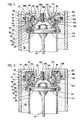
- an improved, pneumatically powered, fastener-driving tool 10 constitutes a preferred embodiment of this invention.
- the improved tool 10 is similar to known tools, as exemplified by PASLODE 5300C Series Nailers discussed above.
- the improved tool 10 differs markedly from known tools in that the improved tool 10 employs an elastomeric member for biasing a valve member in one axial direction, permitting the valve member to be axially moved in an opposite direction, and for functioning as a bumper between the valve member and a housing structure of the improved tool 10.
- directional terms such as “upwardly”, “downwardly”, “upper”, and “lower” refer to the improved tool in a convenient orientation and are not intended to restrict this invention to any particular orientation of the improved tool 10.
- the improved tool comprises a housing structure 12, which includes various assembled elements including an upper, removable cap 14 defining an annular, downwardly opening, upper chamber 16.
- the housing structure 12 is made from an aluminum alloy.
- dissimilar metals are not used to assemble the housing structure 12.
- the upper cap 14 is fastened suitably and removably to other elements of the housing structure 12 and has a lower surface 18 facing the upper chamber 16.
- the upper chamber 16 has a port 20, via which the upper chamber 16 is pressurized with compressed air in a known manner and via which compressed air in the upper chamber 16 is exhausted to ambient air when a trigger 22 of the improved tool 10 is actuated in a known manner.
- the improved tool 10 comprises a tubular cylinder 30 defining an axis.
- the cylinder 30 is mounted fixedly within the housing structure 12.
- a separate, upper, annular, sealing lip 32 is mounted fixedly to the cylinder 30.
- the cylinder 30 co-acts with surrounding elements of the housing structure 12 to define an annular chamber 34 around an upper portion 36 of the cylinder 30.
- the improved tool 10 comprises a driving piston 40 movable axially within the cylinder 30 between an upper position and a lower position and a driving blade 42 mounted to the driving piston 40 so as to be conjointly movable with the driving piston 40.
- the driving piston 40 has a radially outwardly opening, annular groove 44, in which a nitrile O-ring 46 engaging the cylinder 30 is seated.
- the driving piston 40 and the driving blade 42 are shown in the upper position.
- the driving piston 40 and the driving blade 42 are shown as having been moved downwardly from the upper position, toward the lower position, so as to drive a fastener (not shown) from the improved tool 10 in a known manner.
- the improved tool 10 comprises a valve member 50 movable axially within the housing structure 12, above the upper sealing lip 32 of the cylinder 30, between an upper position and a lower position.
- the valve member 50 is a valve piston.
- the valve piston 50 is shown in the lower position.
- the valve piston 50 is shown in an intermediate position.
- the valve piston 50 is shown in the upper position.
- the valve piston 50 is made from a polymeric material, such as an acetyl polymer or nylon 6/6. An acetyl polymer is preferred.
- the valve piston 50 has an annular portion 52, which has an outer, cylindrical wall 54, an inner, cylindrical wall 56, an upper, annular surface 58 facing the upper chamber 16, and a lower, annular surface 60 facing the annular chamber 34.
- the valve piston 50 has a downwardly extending portion 62, which has a tubular wall 64 extending below the annular portion 52 and a lower, annular flange 66.
- the lower flange 66 flares outwardly and downwardly, so as to have an upper, flared surface 68.
- the downwardly extending portion has an upper surface 70, which faces the upper chamber 16 and which is co-planar with the upper surface 58 of the annular portion 52 of the valve piston 50.
- the improved tool 10 comprises a sealing member 80, which has an upper, tubular wall 82 and a lower, annular flange 84 provided with an integral, lower, annular, sealing lip 86 conforming to the sealing lip 32 of the cylinder 30.
- the sealing member 80 is movable between a lower position and an upper position. In the lower position, as shown in Figures 1, 2, and 3, the sealing lip 32 of the cylinder and the sealing lip 86 of the sealing member 80 are engaged with each other so as to provide an annular seal. In the upper position, the sealing lip 32 of the cylinder and the sealing lip 86 of the sealing member 80 are disengaged from each other.
- the upper wall 82 of the sealing member 80 surrounds the upper wall 64 of the lower portion 62 of the valve piston 60.
- the lower flange 84 of the sealing member 80 flares outwardly and downwardly and surrounds the lower flange 66 of the lower portion 62 of the valve piston 60.
- the lower flange 84 of the sealing member 80 has an upper, flared surface 90 with an effective surface area, as viewed downwardly along the axis, which is smaller than the effective surface area of the lower surface 60 of the annular portion 52 of the valve piston 50, as viewed upwardly along the axis.
- the lower flange 84 of the sealing member 80 has a lower, flared surface 92 conforming to the upper, flared surface 68 of the lower flange 66 of the lower portion 62 of the valve piston 60, so as to provide an annular seal if the flared surface 92 and the flared surface 68 are engaged with each other.
- an annular, elastomeric member 100 is located within the upper chamber of the housing structure 12.
- the elastomeric member 100 is made from polyurethane (80 durometer).
- the elastomeric element 100 is frusto-conical when unstressed but is arranged to be axially stressed within the upper chamber 16 even when the valve piston 50 is in its lower position.
- the elastomeric element 100 is engaged with the lower surface 18 of the upper cap 14 of the housing structure 12 and with the upper surface 70 of the downwardly depending portion 62 of the valve piston 50.
- the elastomeric member 100 biases the valve piston 50 downwardly to its lower position and permits the valve piston 50 to be upwardly moved to its upper position. Moreover, the elastomeric member 100 functions as a bumper between the upper surface 58 of the annular portion 52 of the valve piston 50 and the lower surface 18 of the upper cap 14 of the housing structure 12 when the valve piston 50 is moved upwardly.
- the upper cap 14 has a radially inwardly facing, cylindrical wall 102 facing the upper chamber 16 and having an annular groove 104 opening radially inwardly.
- a nitrile O-ring 106 is seated in the annular groove 104.
- the upper, annular portion 52 of the valve piston 50 has an outer, cylindrical wall 112, which is engaged by the O-ring 106 as the valve piston 50 is moved between its upper and lower positions, and an outer, cylindrical wall 114. Because the valve piston 50 is made from a polymeric material having an inherent lubricity, wear and tear on the O-ring 106 engaging the valve piston 50 is minimized.
- the upper cap 14 has a radially outwardly facing, cylindrical wall 122, which has an annular groove 124 opening radially inwardly.
- a nitrile O-ring 126 is seated in the annular groove 124 and engages the inner wall 114 of the upper, annular portion 52 of the valve piston 52 as the valve piston 50 is moved between its upper and lower positions. Because the valve piston 50 is made from a polymeric material having an inherent lubricity, wear and tear on the O-ring 126 engaging the valve piston 50 is minimized.
- the annular portion 52 of the valve piston 50 and the lower portion 62 of the valve piston 50 are assembled via a retaining clip 130.
- a nitrile O-ring 132 is interposed between the assembled portions 52, 62, which are configured to accommodate the O-ring 132 there-between.
- a nitrile O-ring 142 is seated in a radially outwardly opening, annular groove 144 in the lower, tubular portion 62 of the valve piston 50 and engages the upper, tubular wall 82 of the sealing member 80.
- the housing structure 12 comprises a central element 150, which is fastened to the upper cap 14 via a machine screw 152 and which has a downwardly depending, flared flange 154 with a lower, annular lip 156.
- a nitrile O-ring 162 is seated in a radially outwardly opening annular groove 164 in the lower lip 156 and engages the lower, tubular portion 62 of the valve piston 50.
- the upper cap 14 of the housing structure 12 has a central, annular portion 160, which has axially oriented, exhaust ports 162.
- the lower, tubular portion 62 of the valve piston 50 has radially oriented, exhaust ports 164.
- the upper chamber 16 and the annular chamber 34 are charged with compressed air.
- the elastomeric member 100 biases the valve piston 50 downwardly such that the sealing lip 86 of the sealing member 80 is engaged with the sealing lip 32 of the cylinder so as to provide an annular seal between the annular chamber 34 and the exhaust ports 164 in the lower, tubular portion 62 of the valve piston 50.
- the improved tool 10 may be structurally and functionally similar to known tools, as exemplified by PASLODE 5300C Series Nailers discussed above.
- the elastomeric member 100 When the valve piston 50 is moved upwardly, the elastomeric member 100 functions as a bumper between the upper surface 58 of the annular portion 52 of the valve piston 50 and the lower surface 18 of the upper cap 14 of the housing structure 12.
Landscapes
- Physics & Mathematics (AREA)
- Fluid Mechanics (AREA)
- Engineering & Computer Science (AREA)
- Mechanical Engineering (AREA)
- Portable Nailing Machines And Staplers (AREA)
Applications Claiming Priority (2)
| Application Number | Priority Date | Filing Date | Title |
|---|---|---|---|
| US31918794A | 1994-10-06 | 1994-10-06 | |
| US319187 | 1994-10-06 |
Publications (1)
| Publication Number | Publication Date |
|---|---|
| EP0705664A1 true EP0705664A1 (de) | 1996-04-10 |
Family
ID=23241221
Family Applications (1)
| Application Number | Title | Priority Date | Filing Date |
|---|---|---|---|
| EP95306808A Withdrawn EP0705664A1 (de) | 1994-10-06 | 1995-09-27 | Pneumatisch betätigtes Eintreibgerät für Befestigungsmittel |
Country Status (6)
| Country | Link |
|---|---|
| EP (1) | EP0705664A1 (de) |
| JP (1) | JPH08206974A (de) |
| KR (1) | KR960013581A (de) |
| BR (1) | BR9504766A (de) |
| CA (1) | CA2158802A1 (de) |
| MX (1) | MX9504069A (de) |
Families Citing this family (3)
| Publication number | Priority date | Publication date | Assignee | Title |
|---|---|---|---|---|
| JP4507384B2 (ja) * | 2000-10-23 | 2010-07-21 | マックス株式会社 | 釘打機における排気構造 |
| JP5730752B2 (ja) * | 2011-12-28 | 2015-06-10 | 株式会社マキタ | エア打込み工具 |
| JP2018118368A (ja) * | 2017-01-27 | 2018-08-02 | 工機ホールディングス株式会社 | 打込機 |
Citations (7)
| Publication number | Priority date | Publication date | Assignee | Title |
|---|---|---|---|---|
| US3392632A (en) * | 1965-02-04 | 1968-07-16 | Haubold Dieter | Valve means for an air-operated fastener device |
| DE2223999A1 (de) * | 1972-05-17 | 1974-01-31 | ||
| EP0205633A1 (de) * | 1985-06-21 | 1986-12-30 | Joh. Friedrich Behrens AG | Ventilanordnung |
| EP0359974A2 (de) * | 1988-09-17 | 1990-03-28 | Haubold-Kihlberg Gmbh | Durch Druckluft betriebenes Schlaggerät mit Entlüftungsventil für das Hauptventil |
| FR2661353A1 (fr) * | 1990-04-27 | 1991-10-31 | Sofragraf Ind | Appareil de clouage pneumatique. |
| EP0584395A1 (de) * | 1992-08-28 | 1994-03-02 | Umberto Monacelli | Pneumatisches Befestigungsmitteleintreibgerät mit verbesserten Kolben |
| EP0584394A1 (de) * | 1992-08-28 | 1994-03-02 | Umberto Monacelli | Pneumatisches Befestigungsmitteleintreibgerät mit verbessertem Ventil |
-
1995
- 1995-09-21 CA CA002158802A patent/CA2158802A1/en not_active Abandoned
- 1995-09-22 MX MX9504069A patent/MX9504069A/es unknown
- 1995-09-27 EP EP95306808A patent/EP0705664A1/de not_active Withdrawn
- 1995-10-03 JP JP7278298A patent/JPH08206974A/ja active Pending
- 1995-10-03 BR BR9504766A patent/BR9504766A/pt not_active IP Right Cessation
- 1995-10-04 KR KR1019950033777A patent/KR960013581A/ko not_active Ceased
Patent Citations (7)
| Publication number | Priority date | Publication date | Assignee | Title |
|---|---|---|---|---|
| US3392632A (en) * | 1965-02-04 | 1968-07-16 | Haubold Dieter | Valve means for an air-operated fastener device |
| DE2223999A1 (de) * | 1972-05-17 | 1974-01-31 | ||
| EP0205633A1 (de) * | 1985-06-21 | 1986-12-30 | Joh. Friedrich Behrens AG | Ventilanordnung |
| EP0359974A2 (de) * | 1988-09-17 | 1990-03-28 | Haubold-Kihlberg Gmbh | Durch Druckluft betriebenes Schlaggerät mit Entlüftungsventil für das Hauptventil |
| FR2661353A1 (fr) * | 1990-04-27 | 1991-10-31 | Sofragraf Ind | Appareil de clouage pneumatique. |
| EP0584395A1 (de) * | 1992-08-28 | 1994-03-02 | Umberto Monacelli | Pneumatisches Befestigungsmitteleintreibgerät mit verbesserten Kolben |
| EP0584394A1 (de) * | 1992-08-28 | 1994-03-02 | Umberto Monacelli | Pneumatisches Befestigungsmitteleintreibgerät mit verbessertem Ventil |
Also Published As
| Publication number | Publication date |
|---|---|
| JPH08206974A (ja) | 1996-08-13 |
| MX9504069A (es) | 1997-02-28 |
| KR960013581A (ko) | 1996-05-22 |
| BR9504766A (pt) | 1996-10-15 |
| CA2158802A1 (en) | 1996-04-07 |
Similar Documents
| Publication | Publication Date | Title |
|---|---|---|
| US7850055B2 (en) | Assembly having gasket resistant to side loading by pressurized fluid | |
| US5197646A (en) | Combustion-powered tool assembly | |
| US7316341B2 (en) | Adjustable exhaust assembly for pneumatic fasteners | |
| AU2010224437B2 (en) | Beam system membrane suspension for a motor mount | |
| EP2012977B1 (de) | Pneumatisch bedienbares eintreibwerkzeug sowie betriebsverfahren dafür | |
| US20050279802A1 (en) | Seal for portable fastener driving tool | |
| EP0705664A1 (de) | Pneumatisch betätigtes Eintreibgerät für Befestigungsmittel | |
| US4763562A (en) | Poppet valve with improved seal for pneumatic fastener driving apparatus | |
| EP1954448B1 (de) | Einwegeventil für einen gebläsemotor eines brennkraftbetriebenen werkzeugs | |
| US20080272326A1 (en) | Driving tool and head valve assembly for a driving tool | |
| CN102271875B (zh) | 改善的气动工具驱动装置 | |
| US4646852A (en) | Pneumatic mallet | |
| EP0472271B1 (de) | Kolbenaufbau für Einschlagmaschine für Befestigungsmittel | |
| SE469971B (sv) | Tryckmediumdriven slagmekanism | |
| AU2012244211A1 (en) | Beam system membrane suspension for a motor mount |
Legal Events
| Date | Code | Title | Description |
|---|---|---|---|
| PUAI | Public reference made under article 153(3) epc to a published international application that has entered the european phase |
Free format text: ORIGINAL CODE: 0009012 |
|
| AK | Designated contracting states |
Kind code of ref document: A1 Designated state(s): DE FR GB IT SE |
|
| 17P | Request for examination filed |
Effective date: 19960927 |
|
| STAA | Information on the status of an ep patent application or granted ep patent |
Free format text: STATUS: THE APPLICATION HAS BEEN WITHDRAWN |
|
| 18W | Application withdrawn |
Withdrawal date: 19970717 |