EP0705700A1 - Cheminées multiples pour imprimante à jet d'encre - Google Patents
Cheminées multiples pour imprimante à jet d'encre Download PDFInfo
- Publication number
- EP0705700A1 EP0705700A1 EP95306652A EP95306652A EP0705700A1 EP 0705700 A1 EP0705700 A1 EP 0705700A1 EP 95306652 A EP95306652 A EP 95306652A EP 95306652 A EP95306652 A EP 95306652A EP 0705700 A1 EP0705700 A1 EP 0705700A1
- Authority
- EP
- European Patent Office
- Prior art keywords
- printheads
- ink
- chimneys
- reservoir
- ink droplets
- Prior art date
- Legal status (The legal status is an assumption and is not a legal conclusion. Google has not performed a legal analysis and makes no representation as to the accuracy of the status listed.)
- Granted
Links
- 230000007246 mechanism Effects 0.000 claims abstract description 24
- 238000007641 inkjet printing Methods 0.000 claims abstract description 17
- 238000000034 method Methods 0.000 claims description 10
- 239000000443 aerosol Substances 0.000 claims description 6
- 238000002156 mixing Methods 0.000 claims description 4
- 229920000642 polymer Polymers 0.000 claims description 4
- 239000013528 metallic particle Substances 0.000 claims 1
- 239000000976 ink Substances 0.000 abstract description 68
- 238000007639 printing Methods 0.000 abstract description 14
- 239000002244 precipitate Substances 0.000 abstract description 8
- 230000002745 absorbent Effects 0.000 description 5
- 239000002250 absorbent Substances 0.000 description 5
- 238000010438 heat treatment Methods 0.000 description 5
- 239000002699 waste material Substances 0.000 description 4
- 230000008021 deposition Effects 0.000 description 3
- 230000037452 priming Effects 0.000 description 3
- 230000004888 barrier function Effects 0.000 description 2
- 239000003086 colorant Substances 0.000 description 2
- 238000010304 firing Methods 0.000 description 2
- 239000000463 material Substances 0.000 description 2
- 239000000203 mixture Substances 0.000 description 2
- 238000001556 precipitation Methods 0.000 description 2
- 229920002799 BoPET Polymers 0.000 description 1
- 239000005041 Mylar™ Substances 0.000 description 1
- 239000000853 adhesive Substances 0.000 description 1
- 230000001070 adhesive effect Effects 0.000 description 1
- 230000015572 biosynthetic process Effects 0.000 description 1
- 238000010276 construction Methods 0.000 description 1
- 238000001035 drying Methods 0.000 description 1
- 230000000694 effects Effects 0.000 description 1
- 150000001455 metallic ions Chemical class 0.000 description 1
- 238000012986 modification Methods 0.000 description 1
- 230000004048 modification Effects 0.000 description 1
- 239000000049 pigment Substances 0.000 description 1
- 238000002360 preparation method Methods 0.000 description 1
- 239000007787 solid Substances 0.000 description 1
- 238000005507 spraying Methods 0.000 description 1
Images

Classifications
-
- B—PERFORMING OPERATIONS; TRANSPORTING
- B41—PRINTING; LINING MACHINES; TYPEWRITERS; STAMPS
- B41J—TYPEWRITERS; SELECTIVE PRINTING MECHANISMS, i.e. MECHANISMS PRINTING OTHERWISE THAN FROM A FORME; CORRECTION OF TYPOGRAPHICAL ERRORS
- B41J2/00—Typewriters or selective printing mechanisms characterised by the printing or marking process for which they are designed
- B41J2/005—Typewriters or selective printing mechanisms characterised by the printing or marking process for which they are designed characterised by bringing liquid or particles selectively into contact with a printing material
- B41J2/01—Ink jet
- B41J2/135—Nozzles
- B41J2/165—Prevention or detection of nozzle clogging, e.g. cleaning, capping or moistening for nozzles
- B41J2/16505—Caps, spittoons or covers for cleaning or preventing drying out
- B41J2/16508—Caps, spittoons or covers for cleaning or preventing drying out connected with the printer frame
Definitions
- This invention relates to inkjet printing mechanisms, and more particularly, to mechanisms for controlling inkjet aerosol in ink-jet printers, plotters, scanners, facsimile machines, and the like.
- An inkjet printing mechanism is a type of non-impact printing device which forms characters and other images by controllably spraying drops of ink from a printhead.
- Inkjet printing mechanisms may be employed in a variety of devices, such as printers, plotters, scanners, facsimile machines, and the like. For convenience, inkjet printers are used herein to illustrate the concepts of the present invention.
- the printhead ejects ink through multiple nozzles in the form of drops which travel across a small air gap and land on a recording media. Different nozzles are employed for different colors. The drops are very small. Inkjet printers commonly print within a range of 180 to 600 dots per inch (dpi). The ink drops dry on the recording media shortly after deposition to form the desired printed images.
- dpi dots per inch
- inkjet printheads there are various types of inkjet printheads including, for example, thermal inkjet printheads and piezoelectric inkjet printheads.
- thermal inkjet printhead ink droplets are ejected from individual nozzles by localized heating.
- a small heating element is disposed at individual nozzles.
- An electrical current is passed through the element to heat it up. This causes a tiny volume of ink to be rapidly heated and vaporized by the heating element. Once vaporized, the ink is ejected through the nozzle.
- a driver circuit is coupled to individual heating elements to provide the energy pulses and thereby controllably deposit ink drops from associated individual nozzles.
- Such drivers are responsive to character generators and other image forming circuitry to energize selected nozzles of the printhead for forming desired images on the recording media.
- a unique reservoir assembly for use in an inkjet printing mechanism.
- the reservoir assembly includes a plurality of chimneys which collect ink droplets ejected by inkjet nozzles during a servicing mode. Different nozzles deposit droplets in different chimneys.
- the chimneys channel waste ink to one or more collection areas which collect the waste ink.
- one chimney receives black ink, and another chimney receives color ink.
- absorbent material such as an absorbent pad
- absorbent material is provided in the collection area or areas and absorbs ink deposited therein.
- the chimneys channel the waste ink to a collection area that is larger in volume than a collection area that could be employed if the chimneys were omitted and ink was deposited from the nozzles directly into the collection area.
- two chimneys lead to a single reservoir where ink from the separate chimneys mix together.
- the reservoir contains an absorbent pad, and ink from the separate chimneys mix together on the pad, which mixing results in the formation of a precipitate at a location between the chimneys. Because the precipitate forms laterally between the chimneys, it is far enough away from each chimney that clogging of the chimneys is avoided.
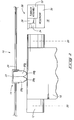
- Fig. 1 is a diagrammatical side view of one form of an inkjet printing mechanism according to this invention.
- Fig. 1 shows a movable carriage, holding a printhead, and a reservoir assembly including two chimneys for receiving ink during a servicing mode.
- Fig. 2 is a top view of the reservoir assembly of Fig. 1, showing a flow path of ink received from the printhead into one of the chimneys.
- Fig. 3 is a top view of the reservoir assembly of Fig. 1, showing a flow path of ink received from the printhead into the other of the chimneys.
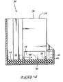
- Fig. 4 is a cut away side elevational view of the reservoir assembly of Fig. 1.
- an inkjet printing mechanism has one or more inkjet printheads which controllably deposit drops of ink in prescribed patterns onto a recording media.
- recording media includes all forms of printable matter including, for example, continuous paper, sheet stock paper, adhesive backed labels, mylar, and the like.
- a typical inkjet printhead has multiple nozzles (e.g., 50 nozzles), such as that described in U.S. Patent No. 5,278,584 by Keefe et al., which is assigned to Hewlett-Packard Company, and which is incorporated herein by reference.
- Fig. 1 shows one embodiment of a shuttle-type inkjet printing mechanism 10 constructed according to this invention.
- Printing mechanism 10 includes a platen 12, a shuttle assembly 14, and a service station 16.
- Platen 12 supports a recording media 18 during printing.
- the platen can be stationary, or rotatable to assist in advancing the media through the printing mechanism.
- a media feed mechanism (not shown), such as conventional friction rollers or a tractor feed system, may be used to drive the media through the printing mechanism along a media feed path.
- Printing mechanism 10 has a predefined print zone which is represented by dashed boundary lines 20.
- the print zone coincides at least partially with the media feed path so that the recording media is fed through the print zone.
- An example print zone is defined as an area within which each of the multiple printheads can print across the entire width of the recording media.
- Shuttle assembly 14 includes a carriage 22 slidably mounted on a fixed, elongated guide rod 24 to move bidirectionally across platen 12.
- carriage 22 is designed to maneuver over the full width of the platen, thereby entirely traversing print zone 20, as well as moving to service station 16 outside of the print zone. It is noted, however, that the service station may be located within or under the print zone.
- Shuttle assembly 14 includes a drive subassembly (not shown) that is mechanically coupled to drive carriage 22 back and forth along guide rod 24.
- a typical drive subassembly includes a wire or belt attached to carriage 22 and wound around opposing pulleys, and a motor (e.g., a stepper motor or DC motor) connected to power one of the pulleys.
- a rotary or linear encoder is often coupled to the motor drive shaft to monitor incremental shaft rotation and provide feedback data for use in positioning and controlling the carriage, although some printers can be embodied without an encoder.
- the shuttle assembly 14 described herein is provided for explanation purposes and its construction is well known in the art. Other types of shuttle assembly configurations may alternatively be employed.
- Carriage 22 supports and carries two printheads 26a and 26b which are preferably embodied as replaceable, disposable print cartridges or pens.
- Printheads 26a and 26b are mounted to carriage 22 so that their nozzle sections 28a and 28b are adjacent to, but spaced from, platen 12 to permit passage of the recording media therebetween.
- the carriage 22 moves the printhead back and forth through print zone 20 in horizontal swaths along a scan axis.
- printhead 26a is a multi-color pen which deposits multiple colors, such as Cyan, Magenta, and Yellow.
- An example multi-color printhead is sold by Hewlett-Packard under part number 51625A.
- printhead 26b is a monochrome pen which deposits black ink.
- Carriage 22 is illustrated as moving printheads 26a and 26b out of print zone 20 to service station 16 where the printheads are serviced.
- Service station 16 is preferably located adjacent to platen 12 and outside of print zone 20, although it may alternatively be located within or under the print zone.
- the printheads 26a and 26b are moved to the service station during initialization procedures and then intermittently during printing.
- the printheads 26a and 26b undergo various servicing processes at the service station including "spitting" where the printheads 26a and 26b fire multiple ink droplets to clear the nozzles and orifices of any ink build-up or debris.
- Service station 16 has a reservoir assembly 30 for receiving the ink droplets ejected from the printhead 26 during the servicing mode.
- Reservoir assembly 30 includes a reservoir 32 to collect the ink droplets, and includes side by side chimneys 34 and 36 positioned intermediate of the printheads 26a and 26b and reservoir 32 to guide the ink droplets from the printheads into the reservoir 32.
- a common wall separates the chimneys 34 and 36.
- the chimneys 34 and 36 extend vertically and carry the ink droplets vertically downwardly in the direction shown in Figs. 2 and 3 by the arrows.
- the chimneys 34 and 36 have generally rectangular cross sections, although other shapes are possible.
- nozzle sections 28a and 28b of printheads 26a and 26b are adjacent to, but spaced slightly above, chimneys 34 and 36 when the printheads are positioned above the reservoir assembly 30.
- the printhead nozzle sections 28a and 28b are spaced from the top of the chimneys 34 and 36 by a distance of approximately 0.5 to 2 mm.
- the printheads 26a and 26b are fired many times (perhaps hundreds or thousands of times) to clear the nozzles and orifices of any ink build-up or debris.
- the printheads 26a and 26b can be fired either simultaneously or at separate times.
- the ink droplets exit the printheads 26a and 26b at a comparatively high velocity into the chimneys 34 or 36.
- the ink droplets entrain the surrounding air to create an air flow into the reservoir.
- the chimney 34 has two lower openings 38 and 40, and ink travelling down chimney 34 diverges (Fig. 3) at these openings 38 and 40 to travel to areas 42 and 44 at the bottom of the reservoir 32.
- the chimney 36 has a single lower opening 46 (Fig. 2), and ink travelling down chimney 36 travels to area 48 at the bottom of the reservoir 32.
- printhead 26a deposits droplets into chimney 34
- printhead 26b deposits droplets into chimney 36.
- the chimneys 34 and 36 channel waste ink from the different printheads 26a and 26b to different collection areas 42 and 44, and 48 of the common reservoir 32.
- absorbent material such as an absorbent pad 50, is provided at the bottom of the reservoir 32 and collects ink deposited to the areas 42, 44, and 46.
- one chimney receives black ink
- another chimney receives color ink.
- the printhead 26a is a color printhead and fires ink into chimney 34
- the printhead 26b is a black printhead and fires ink into chimney 36.
- a precipitate forms when the black ink meets the color ink on the pad 50. This is how the latest inks prevent mixing when color contacts black.
- the black ink has a charged polymer attached to black pigment to make it dispersible.
- the color ink contains dissolved metallic ions of the opposite charge. When the color ink meets the black ink, the black polymer charge is neutralized and a solid precipitates out of solution.
- the precipitate forms a natural barrier between the area 48 and the area 44; and between the area 48 and the area 42.
- short vertical barriers 54 are also provided to separate these areas at least for a predetermined horizontal distance from the chimneys.
- separate chimneys are provided for receiving the different color inks.
- tumbler assembly 52 which is located above the areas 42, 44, and 48 of the reservoir 32.
- the tumbler assembly performs such processes as: “wiping” where wipers physically wipe the respective nozzle sections of the printheads 26a and 26b to clean them; "priming” where a pressure gradient is created within the ink conduits of the printhead 26 to prepare the ink stream for continuous flow into the ejecting heating element or to forcibly remove trapped air bubbles and other debris; and “capping" to prevent ink in the printheads 26a and 26b from drying out.
- the tumbler assembly 52 includes structure for performing the "wiping", “priming", and “capping".
- the tumbler assembly 52 and reservoir assembly 30 are a modular unit that can be replaced as a unit if any subcomponent of the tumbler assembly 52 or reservoir assembly 30 fails.
- the reservoir 32 is designed to accommodate ink for the lifetime of the printing mechanism 10, and should not need emptying.
- the reservoir assembly of this invention is advantageous because it provides an efficient and effective technique for controlling inkjet aerosol. Additionally, precipitates which tend to cause clogging and shorten the life of reservoirs can be kept away from the chimneys.
Landscapes
- Ink Jet (AREA)
Applications Claiming Priority (4)
| Application Number | Priority Date | Filing Date | Title |
|---|---|---|---|
| US08/316,152 US5563639A (en) | 1994-09-30 | 1994-09-30 | Venturi spittoon system to control inkjet aerosol |
| US316152 | 1994-09-30 | ||
| US379235 | 1995-01-27 | ||
| US08/379,235 US5680162A (en) | 1994-09-30 | 1995-01-27 | Multiple chimneys for ink jet printer |
Publications (2)
| Publication Number | Publication Date |
|---|---|
| EP0705700A1 true EP0705700A1 (fr) | 1996-04-10 |
| EP0705700B1 EP0705700B1 (fr) | 1998-05-20 |
Family
ID=26980273
Family Applications (1)
| Application Number | Title | Priority Date | Filing Date |
|---|---|---|---|
| EP19950306652 Expired - Lifetime EP0705700B1 (fr) | 1994-09-30 | 1995-09-20 | Cheminées multiples pour imprimante à jet d'encre |
Country Status (4)
| Country | Link |
|---|---|
| EP (1) | EP0705700B1 (fr) |
| JP (1) | JPH08207267A (fr) |
| DE (1) | DE69502565T2 (fr) |
| ES (1) | ES2119319T3 (fr) |
Cited By (1)
| Publication number | Priority date | Publication date | Assignee | Title |
|---|---|---|---|---|
| CN117818214A (zh) * | 2024-01-29 | 2024-04-05 | 深圳市润天智数字设备股份有限公司 | 一种扫描式喷墨设备和喷头清洁方法 |
Citations (5)
| Publication number | Priority date | Publication date | Assignee | Title |
|---|---|---|---|---|
| US4362572A (en) * | 1981-06-25 | 1982-12-07 | Burroughs Corporation | Method and apparatus for cleaning ink jet printer heads |
| US4967204A (en) * | 1985-10-01 | 1990-10-30 | Canon Kabushiki Kaisha | Method for ensuring stable operation of an ink jet recording apparatus |
| EP0465260A2 (fr) * | 1990-07-05 | 1992-01-08 | Hewlett-Packard Company | Méthode et appareil de nettoyage d'une plaque à orifice de gicleurs d'encre |
| EP0574268A1 (fr) * | 1992-06-12 | 1993-12-15 | Canon Kabushiki Kaisha | Dispositif de récupération, appareil à jet d'encre muni du dispositif et méthode de récupération |
| US5278584A (en) | 1992-04-02 | 1994-01-11 | Hewlett-Packard Company | Ink delivery system for an inkjet printhead |
-
1995
- 1995-09-20 EP EP19950306652 patent/EP0705700B1/fr not_active Expired - Lifetime
- 1995-09-20 DE DE1995602565 patent/DE69502565T2/de not_active Expired - Lifetime
- 1995-09-20 ES ES95306652T patent/ES2119319T3/es not_active Expired - Lifetime
- 1995-09-29 JP JP27650995A patent/JPH08207267A/ja active Pending
Patent Citations (5)
| Publication number | Priority date | Publication date | Assignee | Title |
|---|---|---|---|---|
| US4362572A (en) * | 1981-06-25 | 1982-12-07 | Burroughs Corporation | Method and apparatus for cleaning ink jet printer heads |
| US4967204A (en) * | 1985-10-01 | 1990-10-30 | Canon Kabushiki Kaisha | Method for ensuring stable operation of an ink jet recording apparatus |
| EP0465260A2 (fr) * | 1990-07-05 | 1992-01-08 | Hewlett-Packard Company | Méthode et appareil de nettoyage d'une plaque à orifice de gicleurs d'encre |
| US5278584A (en) | 1992-04-02 | 1994-01-11 | Hewlett-Packard Company | Ink delivery system for an inkjet printhead |
| EP0574268A1 (fr) * | 1992-06-12 | 1993-12-15 | Canon Kabushiki Kaisha | Dispositif de récupération, appareil à jet d'encre muni du dispositif et méthode de récupération |
Cited By (1)
| Publication number | Priority date | Publication date | Assignee | Title |
|---|---|---|---|---|
| CN117818214A (zh) * | 2024-01-29 | 2024-04-05 | 深圳市润天智数字设备股份有限公司 | 一种扫描式喷墨设备和喷头清洁方法 |
Also Published As
| Publication number | Publication date |
|---|---|
| DE69502565T2 (de) | 1998-09-10 |
| JPH08207267A (ja) | 1996-08-13 |
| EP0705700B1 (fr) | 1998-05-20 |
| DE69502565D1 (de) | 1998-06-25 |
| ES2119319T3 (es) | 1998-10-01 |
Similar Documents
| Publication | Publication Date | Title |
|---|---|---|
| US5680162A (en) | Multiple chimneys for ink jet printer | |
| US5694157A (en) | Multiple wiper servicing system for inkjet printheads | |
| US6935717B2 (en) | Ink drop detector configurations | |
| US6050671A (en) | Stalagmite dissolving spittoon system for inkjet printheads | |
| US6491366B1 (en) | Ink drop detector waste ink removal system | |
| US6561621B2 (en) | Vacuum spittoon for collecting ink during servicing of ink jet printheads | |
| US6742864B2 (en) | Waste ink removal system | |
| US6644778B2 (en) | Stalagmite dissolving spittoon system for inkjet printheads | |
| US5943071A (en) | Wiper blade cleaning system for nozzle faces of a color printhead | |
| US6644775B2 (en) | Single actuation axis printhead cleaner architecture for staggered printheads | |
| MXPA96005803A (es) | Sistema de limpieza con aspa limpiadora para caras de boquillas de una cabeza de impresion a color | |
| EP0705700B1 (fr) | Cheminées multiples pour imprimante à jet d'encre | |
| EP2979875B1 (fr) | Appareil de formation d'image à jet d'encre et procédé de nettoyage pour appareil de formation d'image à jet d'encre | |
| KR20040016521A (ko) | 잉크젯 프린터 | |
| US7798601B2 (en) | Ink jet printing apparatus and method for recovering the same | |
| JPH06191060A (ja) | インクジェット記録装置 | |
| KR100547160B1 (ko) | 잉크젯 프린터 | |
| JP2006272597A (ja) | インクジェット記録装置 | |
| JP2001260384A (ja) | インクジェット記録装置 | |
| JP2001113706A (ja) | 記録ヘッド及びインクジェット記録装置 |
Legal Events
| Date | Code | Title | Description |
|---|---|---|---|
| PUAI | Public reference made under article 153(3) epc to a published international application that has entered the european phase |
Free format text: ORIGINAL CODE: 0009012 |
|
| AK | Designated contracting states |
Kind code of ref document: A1 Designated state(s): DE ES FR GB IT |
|
| 17P | Request for examination filed |
Effective date: 19960916 |
|
| 17Q | First examination report despatched |
Effective date: 19970416 |
|
| GRAG | Despatch of communication of intention to grant |
Free format text: ORIGINAL CODE: EPIDOS AGRA |
|
| GRAG | Despatch of communication of intention to grant |
Free format text: ORIGINAL CODE: EPIDOS AGRA |
|
| GRAH | Despatch of communication of intention to grant a patent |
Free format text: ORIGINAL CODE: EPIDOS IGRA |
|
| GRAH | Despatch of communication of intention to grant a patent |
Free format text: ORIGINAL CODE: EPIDOS IGRA |
|
| GRAA | (expected) grant |
Free format text: ORIGINAL CODE: 0009210 |
|
| AK | Designated contracting states |
Kind code of ref document: B1 Designated state(s): DE ES FR GB IT |
|
| ITF | It: translation for a ep patent filed | ||
| REF | Corresponds to: |
Ref document number: 69502565 Country of ref document: DE Date of ref document: 19980625 |
|
| ET | Fr: translation filed | ||
| REG | Reference to a national code |
Ref country code: ES Ref legal event code: FG2A Ref document number: 2119319 Country of ref document: ES Kind code of ref document: T3 |
|
| PLBE | No opposition filed within time limit |
Free format text: ORIGINAL CODE: 0009261 |
|
| STAA | Information on the status of an ep patent application or granted ep patent |
Free format text: STATUS: NO OPPOSITION FILED WITHIN TIME LIMIT |
|
| 26N | No opposition filed | ||
| REG | Reference to a national code |
Ref country code: GB Ref legal event code: 732E |
|
| REG | Reference to a national code |
Ref country code: FR Ref legal event code: TP |
|
| REG | Reference to a national code |
Ref country code: GB Ref legal event code: IF02 |
|
| PGFP | Annual fee paid to national office [announced via postgrant information from national office to epo] |
Ref country code: ES Payment date: 20070926 Year of fee payment: 13 |
|
| PGFP | Annual fee paid to national office [announced via postgrant information from national office to epo] |
Ref country code: IT Payment date: 20070926 Year of fee payment: 13 |
|
| PGFP | Annual fee paid to national office [announced via postgrant information from national office to epo] |
Ref country code: FR Payment date: 20070207 Year of fee payment: 12 |
|
| REG | Reference to a national code |
Ref country code: FR Ref legal event code: ST Effective date: 20080531 |
|
| PG25 | Lapsed in a contracting state [announced via postgrant information from national office to epo] |
Ref country code: FR Free format text: LAPSE BECAUSE OF NON-PAYMENT OF DUE FEES Effective date: 20071001 |
|
| PG25 | Lapsed in a contracting state [announced via postgrant information from national office to epo] |
Ref country code: IT Free format text: LAPSE BECAUSE OF NON-PAYMENT OF DUE FEES Effective date: 20080920 |
|
| REG | Reference to a national code |
Ref country code: ES Ref legal event code: FD2A Effective date: 20080922 |
|
| PG25 | Lapsed in a contracting state [announced via postgrant information from national office to epo] |
Ref country code: ES Free format text: LAPSE BECAUSE OF NON-PAYMENT OF DUE FEES Effective date: 20080922 |
|
| REG | Reference to a national code |
Ref country code: GB Ref legal event code: 732E Free format text: REGISTERED BETWEEN 20120329 AND 20120404 |
|
| PGFP | Annual fee paid to national office [announced via postgrant information from national office to epo] |
Ref country code: GB Payment date: 20120925 Year of fee payment: 18 |
|
| PGFP | Annual fee paid to national office [announced via postgrant information from national office to epo] |
Ref country code: DE Payment date: 20120927 Year of fee payment: 18 |
|
| GBPC | Gb: european patent ceased through non-payment of renewal fee |
Effective date: 20130920 |
|
| REG | Reference to a national code |
Ref country code: DE Ref legal event code: R119 Ref document number: 69502565 Country of ref document: DE Effective date: 20140401 |
|
| PG25 | Lapsed in a contracting state [announced via postgrant information from national office to epo] |
Ref country code: GB Free format text: LAPSE BECAUSE OF NON-PAYMENT OF DUE FEES Effective date: 20130920 |
|
| PG25 | Lapsed in a contracting state [announced via postgrant information from national office to epo] |
Ref country code: DE Free format text: LAPSE BECAUSE OF NON-PAYMENT OF DUE FEES Effective date: 20140401 |