EP0705735A2 - Dispositif de support pour boîtiers, notamment pour boîtiers de dispositifs électroniques dans véhicules utilitaires - Google Patents
Dispositif de support pour boîtiers, notamment pour boîtiers de dispositifs électroniques dans véhicules utilitaires Download PDFInfo
- Publication number
- EP0705735A2 EP0705735A2 EP95112916A EP95112916A EP0705735A2 EP 0705735 A2 EP0705735 A2 EP 0705735A2 EP 95112916 A EP95112916 A EP 95112916A EP 95112916 A EP95112916 A EP 95112916A EP 0705735 A2 EP0705735 A2 EP 0705735A2
- Authority
- EP
- European Patent Office
- Prior art keywords
- housing
- tension spring
- carrier
- latching
- locking
- Prior art date
- Legal status (The legal status is an assumption and is not a legal conclusion. Google has not performed a legal analysis and makes no representation as to the accuracy of the status listed.)
- Granted
Links
Images


Classifications
-
- B—PERFORMING OPERATIONS; TRANSPORTING
- B60—VEHICLES IN GENERAL
- B60R—VEHICLES, VEHICLE FITTINGS, OR VEHICLE PARTS, NOT OTHERWISE PROVIDED FOR
- B60R11/00—Arrangements for holding or mounting articles, not otherwise provided for
- B60R11/02—Arrangements for holding or mounting articles, not otherwise provided for for radio sets, television sets, telephones, or the like; Arrangement of controls thereof
-
- H—ELECTRICITY
- H05—ELECTRIC TECHNIQUES NOT OTHERWISE PROVIDED FOR
- H05K—PRINTED CIRCUITS; CASINGS OR CONSTRUCTIONAL DETAILS OF ELECTRIC APPARATUS; MANUFACTURE OF ASSEMBLAGES OF ELECTRICAL COMPONENTS
- H05K5/00—Casings, cabinets or drawers for electric apparatus
- H05K5/0026—Casings, cabinets or drawers for electric apparatus provided with connectors and printed circuit boards [PCB], e.g. automotive electronic control units
- H05K5/0073—Casings, cabinets or drawers for electric apparatus provided with connectors and printed circuit boards [PCB], e.g. automotive electronic control units having specific features for mounting the housing on an external structure
-
- B—PERFORMING OPERATIONS; TRANSPORTING
- B60—VEHICLES IN GENERAL
- B60R—VEHICLES, VEHICLE FITTINGS, OR VEHICLE PARTS, NOT OTHERWISE PROVIDED FOR
- B60R11/00—Arrangements for holding or mounting articles, not otherwise provided for
- B60R2011/0042—Arrangements for holding or mounting articles, not otherwise provided for characterised by mounting means
- B60R2011/0049—Arrangements for holding or mounting articles, not otherwise provided for characterised by mounting means for non integrated articles
- B60R2011/0064—Connection with the article
- B60R2011/0071—Connection with the article using latches, clips, clamps, straps or the like
-
- B—PERFORMING OPERATIONS; TRANSPORTING
- B60—VEHICLES IN GENERAL
- B60R—VEHICLES, VEHICLE FITTINGS, OR VEHICLE PARTS, NOT OTHERWISE PROVIDED FOR
- B60R11/00—Arrangements for holding or mounting articles, not otherwise provided for
- B60R11/02—Arrangements for holding or mounting articles, not otherwise provided for for radio sets, television sets, telephones, or the like; Arrangement of controls thereof
- B60R2011/027—Arrangements for holding or mounting articles, not otherwise provided for for radio sets, television sets, telephones, or the like; Arrangement of controls thereof for Din-sized apparatus
Definitions
- the invention relates to a housing support arrangement according to the preamble of claim 1.
- Such an arrangement can be used in particular for holding housings of electronic control units in a commercial vehicle, which is equipped with a plurality of such control units for controlling various units.
- the housings of the required control devices are often of different sizes, and it is already known to fasten the housings to a respective carrier part by means of screw connections.
- a device system is known from the published patent application DE 37 43 446 A1, in which devices are detachably connected to one another with their housing via a snap fastening, electrical contacts being provided at the same time.
- the latching connection there includes the arrangement of a pivotable latching hook on one of the two housings, which must be actuated to release the housings.
- Utility model DE 78 08 240 U1 describes a small device arrangement with several individual devices which are held in a common carrier housing.
- the bracket can consist of a snap connection with an actuatable spring catch and a leaf spring arranged on the back of the device as an ejector, so that the latched inserted device is ejected after actuation of the spring catch.
- DE 36 32 470 A1 and DE 36 32 498 A1 disclose devices for fastening electrical switching devices in discloses a device carrier in which the switchgear housing is placed with one side against a corresponding side of the carrier and is subsequently fixed there by means of a locking or tensioning device, which requires a corresponding lever mechanism on the device housing.
- a similar way of fastening a module to a housing wall is described in the published patent application DE 37 11 341 A1. There, a swiveling hook lever articulated on the module is used to secure the module.
- the published patent application EP 0 398 607 A1 discloses a housing for latching a battery.
- the battery is inserted into a recess that is open on one side.
- a spring attached to the inner end of the receptacle presses the battery outwards, while electrical spring contacts are arranged on both sides and a latching mechanism is provided on one side, which is articulated from a latching recess on the battery and one which is articulated on the surrounding housing and by means of a spring into the latching recess depressed locking lever.
- Locking recess and locking lever are designed so that the battery is first pressed beyond its later end position against the force of the rear spring into the recess until the locking lever snaps into the side locking recess, after which the battery is pushed back slightly by the rear spring until a locking lug on the battery recess is received in an associated locking groove on the locking lever and the lever secures the battery against further movement.
- To remove the battery press it back into the recess against the force of the rear spring until the locking connection is released. Then the locking lever can be pivoted against its spring preload into the release position, after which the battery can be removed.
- a holder for an electronics housing in particular a telephone receiver housing, is known, in which the electronics housing is inserted into a recess in the holder that is open on one side.
- One on the back, inside The spring attached to the end of the holder presses the accommodated electronics housing outwards, while a latching lever is provided on one side of the holder, which under spring tension engages in a latching recess of the accommodated electronics housing and secures the latter against moving out.
- the locking lever In order to remove the electronics housing, the locking lever must be pivoted against its spring preload into a release position, after which the electronics housing can be at least partially moved out of the holder by the prestressed spring and then removed by the user.
- a drawer can be inserted into a receiving housing against the pressure of a spring arranged in the latter and can be fastened in a latching manner by the interaction of the locking element pairs.
- the drawer has an operating part which can be tilted about a transverse axis of the drawer, the operating part pushing the respective locking lug out of its locking lug receptacle by this tilting movement, as a result of which the locking is released.
- the release of the lock by means of this tilting movement is intended to prevent the front plate, e.g. to actuate the sensor contacts provided there, due to a resulting slight backward movement of the drawer, the locking lugs are pushed out of their locking lug receptacles and the drawer then moves out of the receiving housing.
- the invention is based on the technical problem of providing a housing support arrangement of the type mentioned at the outset, in which the support has a comparatively low design outlay can be manufactured, the attachment and detachment of a respective housing on the carrier is possible with a high level of operating comfort and several housings can be arranged on the carrier without play and / or in a very space-saving manner.
- a housing support arrangement with the features of claim 1 or 2.
- These arrangements can be assembled not only with a click, but also disassembled with exceptional ease of use simply by handling the housing on the carrier. The latter is done simply by pressing the assembled housing in the plugging direction against the tension spring, whereby the respective locking lug is moved into a position released from its associated receptacle, and then guiding the locking lug out of its assigned receptacle by a slight movement of the housing in the direction perpendicular to the plugging direction.
- the release of the housing from the latching connection with the carrier thus does not require the actuation of a further, movable mounting element.
- no tools are required for assembly and disassembly.
- the accessibility on the front side in the direction of insertion is sufficient, since the latching connection can be made and released again in a direction perpendicular to the direction of insertion by a suitable movement of the housing, essentially parallel to the direction of insertion and to a small extent.
- the housing attachment to the carrier which can be realized in this way can be combined with the choice of a suitable spring constant for the tension springs and a suitable, coordinated design of the holding interacting Design parts to be very vibration-resistant, so that they are particularly suitable for attaching electronic housings to a carrier in a commercial vehicle, where due to road-related vibrations, a high stability of the housing holder on the carrier is required, which, for example, safely withstands acceleration effects up to four times the acceleration due to gravity.
- the arrangement according to claim 1 enables through the acute-angled course of the locking lug side surface a locking and thus stabilizing locking of the locking lug in the assigned locking lug receptacle, the associated edge of which is provided with a corresponding bevel.
- the latching lug can be inserted comfortably into the receptacle and, on the other hand, a latching which is free of play transversely to the plugging direction regardless of manufacturing tolerances.
- the holding plate has locking lug receptacles for the locking lugs of the housings at different depths and / or locking lug receptacles with respect to the plugging direction, in each of which two locking lugs can be accommodated from housings which can be plugged onto opposite holding plate sides.
- control units for a commercial vehicle can be accommodated in two or three standardized housing sizes and the control units available for a particular vehicle can be attached to a single carrier that is the same for all vehicles by simply snapping them on, each with a housing on the top and one can be held on the underside of the holding plate.
- the tension springs are attached to the rear wall of the housing, while the latching lugs are integrally attached to the front wall of the housing are molded.
- a further development of the invention according to claim 4 ensures that when the tensioning spring is placed against the associated stop, both the clamping force against the insertion direction for securing the latching and a securing of the housing position perpendicular to the narrow side surface on the Back of the housing is provided, while this position securing is effected perpendicular to the narrow side surface on the front by the locking lug engaging behind the locking lug recess.
- a further embodiment of this variant according to claim 5 also gives the tension spring the function of securing the position of the housing in the rear area transversely to the direction of insertion in the narrow side plane. This also makes it easier to attach the tension spring to the associated stop.
- a further development of the invention according to claim 7 allows a compact arrangement of several housings on a carrier that can be realized with little manufacturing effort.
- the exemplary embodiments of the invention described below contain various housing support arrangements for the latching fastening of electronic housings of electronic commercial vehicle control devices to a support.
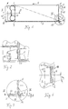
- FIGS. 1 to 4 A first example, in which a housing (1) with an underlying broad side (13) bears against a support plate (3) of a carrier (2), is illustrated in FIGS. 1 to 4.
- the electronics housing (1) has cooling fins (6) on its rear surface (4) and its front surface (5).
- the front surface (5) forms the connector side of the housing (1), on which electrical connections (8) are provided.
- Symmetrical to the longitudinal center plane of the housing (1) is on the rear surface (4) of the housing
- a tension spring unit (9) is arranged on each side area.
- Each tension spring unit (9) consists of two band-shaped tension springs, which are curved to form a three-quarter arc, which are riveted at one end to the rear surface of the housing (4), while the other, free tension spring end is angled in a straight line.
- the two tension springs of each unit (9) are, as can be seen from Fig. 1, mounted symmetrically to the plane of half the height of the housing so that their straight, angled, free ends face each other in a plane parallel to the rear surface of the housing (4), so that in this area
- An indentation (10) of the tension spring unit (9) against a plug-in direction (S) in which the housing (1) is mounted on the carrier (2) is created.
- the housing (1) is secured by the carrier side surfaces (11), which extend approximately to the housing height in the rear housing insertion area and decrease towards the front, ie counter to the direction of insertion (S), linearly up to the height of the support plate (3), such as is indicated by the dashed line in Fig. 1. In the front, lower area of the housing (1), this is snapped into the support plate (3) of the carrier (2).
- the design of the latching connection can be seen more clearly from FIGS. 3 and 4.
- the housing (1) has two latching lugs (14) which are formed laterally on the housing front wall (5) and extend downwards beyond the housing underside (13) and which contain an end shoulder projecting beyond the plug direction (S) beyond the other housing contour.
- the shoulder-forming upper side of the latching lug (14) and the lower side of the web area (16) coming into contact with it are with the slight vertical bevel ( ⁇ ) shown in FIG. 3 with respect to the plane of the lower side of the housing (13 ) or the support plate (3).
- This slight slope ensures a play-free locking bracket even with slight manufacturing-related dimensional deviations, for example in the thickness of the support plate (3) or the distance of the shoulder-forming locking nose top from the other housing underside.
- this slight oblique angle ( ⁇ ) facilitates the latching movement.
- a suitable design of the outer edges of the latching lug openings (15) and the latching lugs (14) in the transverse direction of the housing also stabilizes the housing (1) in the front region parallel to the support plate plane and transversely to the plugging direction (S). Specifically, the side edges facing the longitudinal center of the arrangement run exactly parallel to the plug-in direction (S), while the side edges (17, 18) facing the support side walls (11) run obliquely at an acute angle ( ⁇ 1) of 15 ° to this direction, ie to the longitudinal direction of the housing , run.
- the housing (1) is not only held very securely in place on the carrier (2), but that this is also associated with particularly simple assembly and disassembly.
- it is inserted in the plugging direction (S) along the support plate (3) into the carrier (2) until the tension spring units (9) move against the assigned stops ( 12) create.
- the housing (1) is then pressed further against the tension spring force in the plug-in direction (S), whereby it is slightly lifted from the front of the support plate (3) so that the latching lug (14) can be guided over the web area (16).
- the housing (1) is again placed against the support plate (3) at the front, whereby the latching lugs (14) are guided through the associated latching lug openings (15).
- the pressure of the tension spring units (9) is then given against the plugging direction (S), after which the latching lugs (14) engage behind the support plate (3) by being pushed under their web area (16).
- the narrow sides of the locking lugs (14) bear against the associated opening edge sides, in particular the locking lug inclined surface (18) against the opening edge sloping side (17), the final housing position is reached.
- the housing (1) is parallel to the plug-in direction (S) by the tension spring units (9) supported against the stops (12) and the snap-in connections (14 to 19), perpendicular to the support plate (3) by the contact of the housing underside (13 ) against the support plate (3), which in the tension spring indentations (10) lying stops (12) and the latching lugs (14) engaging behind the carrier plate web areas (16) and transversely to the plugging direction (S) in the carrier plate plane through the carrier side walls (11) and the cooperating narrow sides of the latching lugs (14) and latching lug openings (15) both in each case held securely on the carrier (2) at the rear as well as in the front area.
- the dismantling of the housing (1) from the carrier (2) is just as easy as the assembly by repeating the assembly movements in the opposite direction.
- the housing (1) is first pressed in the plugging direction (S) against the tension spring force until the locking lugs (14) can be led out of the locking lug openings (15), after which the tension spring pressure is given in and the housing counteracts the plugging direction (S ) can be removed from the carrier (2). It follows from this that neither any tool is required to assemble or disassemble the housing (1), nor does any object need to be gripped or actuated in addition to the housing (1).
- this housing support arrangement is also advantageous in terms of construction and manufacturing technology.
- the carrier (2) can be produced as a one-piece molded part without additional elements having to be attached to it. Only the attachment of the tension spring units (9) is necessary on the housing (1), however, no further fastening elements, such as screws or movable snap-in connection parts, are required. Nevertheless, the design of the housing branch attachment shown ensures that it can withstand even jerky impact effects up to four times the acceleration due to gravity, as can occur during operation of the vehicle.
- tension spring units and the locking connections can also be provided on the side of the housing in an area between the front and rear of the housing, the arrangement shown has the advantage that the associated fastening points are maximally spaced in the direction of insertion, which results in a high positional security.
- a housing (21) with a narrow side (27) is held against a carrier formed by a holding plate (22) and latched to the latter.
- the housing (21) is in turn provided on its rear surface (24) with cooling fins (26) and on its front side (25) also with cooling fins (26) and with electrical plug connections (28).
- a band-shaped tension spring (29) with one end is riveted to the rear of the housing (24) in the area adjacent to the narrow side (27) to be placed against the support (22), which in turn is designed to be curved approximately in a three-quarter circle.
- the plate-shaped support (22) has a bow-shaped tension spring stop (23), the contour of which can be seen in FIGS. 5 and 6.
- the bracket (23) forms a U-shaped receptacle (33) that is open against the plugging direction (S), the inner sides (31, 32) of which delimit at an acute angle ( ⁇ 3) of 15 ° in the present case parallel to the plugging direction ( S) and thus extend to the longitudinal direction of the housing in such a way that the receptacle (33) widens counter to the plugging direction (S).
- the tension spring band (29) with its free, angled end (30) can be centered in the bracket receptacle (33) until its width corresponds to the width of the receptacle (33). Due to the angling of the free tension spring end (30), which can be seen in particular in FIG. 5, the tension spring (29) in turn forms an indentation, against which the bracket (23) serving as a tension spring stop comes to rest so that the housing (21) on its rear side (24) is secured against loosening perpendicularly away from the carrier plate (22).
- the simultaneous centering and clamping insertion of the tension spring (29) into the U-shaped receptacle (33) ensures this Housing (21) in its rear area also against movements in the carrier plane transverse to the direction of insertion (S). Parallel to the direction of insertion (S), the housing (21) is held in a spring-elastic manner by pressing the tension spring (29) against the bracket (23) on the support side.
- the housing (21) On the front (25), the housing (21) is fixed by a latching connection which is largely the same as that of the previous example, only a single latching nose (34) being provided here.
- the locking lug (34) can be passed through a locking lug opening (35) and then engages on the underside of a front-side web area (36) of the carrier plate (22) behind its front edge (37) in accordance with the example above.
- This can be seen more precisely in FIG. 7, the contour of the housing (21) being additionally indicated by dashed lines for orientation.
- the top of the shoulder of the latching lug (34) and the underside of the web area (36) are provided with the same, slight bevel ( ⁇ ) with respect to the plane of the carrier plate as described for the example above, with the same advantages as explained above.
- the narrow sides (38) of the housing on the transverse side of the housing are both designed to run obliquely by each making an acute angle ( ⁇ 2) from 15 ° to the longitudinal direction of the housing.
- the associated side edges (39) of the locking lug opening (35) are also both inclined at the same angle ( ⁇ 2) to the plugging direction (S), the opening width decreasing counter to the plugging direction (S).
- this design In cooperation with the tension spring force acting against the plugging direction (S) on the housing (21) and thus the locking lug (34), this design in turn results in a transverse clamping positioning of the locking lug (34) in the opening (35) for backlash-free securing at the front the housing position against movements in the carrier plane transverse to the direction of insertion (S). At the same time, manufacturing tolerances can be compensated.
- the advantages of such a housing support arrangement with a housing that is resiliently spring-loaded on a support can also be transferred to this example.
- the carrier (22) can also be realized as a one-piece molded part without additional elements having to be attached to it.
- the latch (34) is in turn molded onto the housing (21) and only the tension spring (29) is to be riveted on. Assembly and disassembly are only carried out here by handling the housing (21) itself.
- the tension spring (29) is placed against the bracket stop (23) and the housing (21) is pushed in the direction of insertion (S) against the tension spring force until the catch (34) lies above the opening (35) and is then passed through the opening (35) against the carrier plate (22) when the associated narrow side of the housing (27) is subsequently applied. Then the tension spring pressure is given against the plugging direction (S), whereby the locking lug (34) locks with the carrier web area (36) as shown.
- the housing (21) is then held securely on the back and front in all directions, the attachment only being flexible in the plug-in direction (S) against the tension spring force, as is the case in the example above.
- the disassembly is again carried out solely by handling the housing in a movement sequence opposite to the assembly.
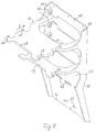
- FIGS. 8 and 9 show an exemplary embodiment in which a plurality of housings (44, 45, 46) manufactured in a standardized manner in three different sizes can be attached to a single, one-piece carrier (40) in a variable and space-saving manner.
- the carrier is in turn manufactured with little manufacturing effort as a one-piece casting without additional elements having to be attached.
- It has a rear wall (41) which is structured such that the carrier (40) can be attached, for example, in front of the footwell in a commercial vehicle cab.
- latching lug openings (42) In the lower half of the rear side (41) there are a plurality of latching lug openings (42) and, at a distance from them downwards, an associated tension spring stop (43), the latter likewise each having an opening in the Carrier rear surface (41) exist.
- a housing (44) of the type described for FIGS. 5 to 7 can be fastened to one tension spring stop opening (43) and the opposite latching lug opening (42) with a narrow side in a latching manner against the carrier rear wall (41).
- the carrier (40) is shown equipped with such a housing (44).
- the free end of the tension spring attached to the rear of the housing, adjacent to a narrow side of the housing, is inserted into the tension spring stop opening (43), the housing (44) is then pressed downwards and inserted with the locking nose formed on the front into the associated locking nose opening (42).
- This type of fastening is intended for the housing with the lowest volume from the set of three housing modules (44, 45, 46) of different sizes.
- All three housing module sizes (44, 45, 46) have the same height.
- the medium-sized case (45) has the same length as the smallest case (44), but a larger width.
- the housing (46) with the largest volume has the same width as the medium-sized housing (45), but a greater length.
- the two larger housings (45, 46) can be fixed on the carrier (40) in the manner of the example described for FIGS. 1 to 4.
- these housing shapes (45, 46) have the structure described for this example above, with the two tension spring units (9) arranged on the side of the rear wall of the housing and the locking lugs (14) formed on the front of the front wall (5).
- two holding plates (48, 49) extend perpendicularly from the rear wall (41) at a distance parallel to one another.
- the one holding plate (48) has a greater length parallel to the plug-in direction of the housing (S) and is offset near its front edge (50) with a first pair of lateral catch-receiving slots (51) and towards the rear wall (41) with a second pair of such catch-receiving slots (52 ) Mistake.
- the other holding plate (53) on the other hand, is shortened and has only a pair of such lateral latch-receiving slots (53), the distance from the rear wall (41) corresponds to that of the latching nose receiving slots (52) on the longer holding plate (48) which are closer to the rear wall (41).
- Tension spring stop cams (47) are formed on the rear wall (41) in the side area above and below each holding plate (48, 49), the shape of which is shown in FIG. 8.
- the tension spring stops (47) also adjoin stiffening carrier side surfaces (54) and each serve to support a housing-side tension spring unit (9), their function corresponding to the angled stop (12) of the example in FIGS. 1 to 4.
- the carrier side areas (54) secure the housing position in the plane of the holding plates (48, 49) transversely to the direction of insertion (S) in the rear area.
- the locking nose receiving slots (51 to 53) take over the function of the locking openings (15) of the example of FIGS.
- each housing can be arranged either on the top or the bottom of a holding plate.
- the medium-sized housings (45) can be mounted specifically on the shortened holding plate (49), in addition to the mounting of the largest housings (46) on the longer holding plate (48) shown in FIG. 9, it is alternatively possible to have one or two housings ( 45) to determine the average size of the same.
- individual housing slots on the carrier (40) can remain unoccupied or a longer housing (46) and a shorter housing (45) can be arranged on the long carrier plate (48) without the retention capacity of the spring-loaded latching connections of all on the carrier ( 40) attached housing is impaired. Consequently, the carrier (40) can be used uniformly for different types of commercial vehicles, it being possible for the electronics housing of the control devices provided for the respective commercial vehicle to be fixed on this carrier (40).
Landscapes
- Engineering & Computer Science (AREA)
- Mechanical Engineering (AREA)
- Microelectronics & Electronic Packaging (AREA)
- Casings For Electric Apparatus (AREA)
- Details Of Connecting Devices For Male And Female Coupling (AREA)
Applications Claiming Priority (2)
| Application Number | Priority Date | Filing Date | Title |
|---|---|---|---|
| DE4435549 | 1994-10-05 | ||
| DE4435549A DE4435549C1 (de) | 1994-10-05 | 1994-10-05 | Gehäuseträgeranordnung, insbesondere von Nutzfahrzeug-Elektronikgehäusen |
Publications (3)
| Publication Number | Publication Date |
|---|---|
| EP0705735A2 true EP0705735A2 (fr) | 1996-04-10 |
| EP0705735A3 EP0705735A3 (fr) | 1997-09-24 |
| EP0705735B1 EP0705735B1 (fr) | 1999-12-08 |
Family
ID=6529992
Family Applications (1)
| Application Number | Title | Priority Date | Filing Date |
|---|---|---|---|
| EP95112916A Expired - Lifetime EP0705735B1 (fr) | 1994-10-05 | 1995-08-17 | Dispositif de support pour boítiers, notamment pour boítiers de dispositifs électroniques dans véhicules utilitaires |
Country Status (2)
| Country | Link |
|---|---|
| EP (1) | EP0705735B1 (fr) |
| DE (1) | DE4435549C1 (fr) |
Cited By (1)
| Publication number | Priority date | Publication date | Assignee | Title |
|---|---|---|---|---|
| CN109353287A (zh) * | 2018-12-14 | 2019-02-19 | 桂林电子科技大学 | 一种车联网控制主机 |
Families Citing this family (4)
| Publication number | Priority date | Publication date | Assignee | Title |
|---|---|---|---|---|
| DE19911990A1 (de) * | 1999-03-17 | 2000-09-28 | Trw Automotive Electron & Comp | Metallgehäuse, insbesondere für ein Airbag-Steuergerät |
| JP4637730B2 (ja) | 2005-11-22 | 2011-02-23 | 矢崎総業株式会社 | ホルダ |
| DE102021127607A1 (de) | 2021-10-25 | 2023-04-27 | Man Truck & Bus Se | Träger für ein Außenverkleidungsteil |
| NL2033505B1 (en) * | 2022-11-11 | 2024-05-28 | Daf Trucks Nv | Vehicle comprising a storage assembly |
Citations (8)
| Publication number | Priority date | Publication date | Assignee | Title |
|---|---|---|---|---|
| DE2314343A1 (de) | 1973-03-22 | 1974-09-26 | Graetz Kg | In einem gehaeuse bewegbare schublade fuer elektronische schalteinheiten |
| DE7808240U1 (de) | 1978-03-17 | 1978-08-31 | Landsrath, Walter, 6600 Saarbruecken | Kleingeräteanordnung |
| DE3632470A1 (de) | 1986-09-24 | 1988-03-31 | Bosch Gmbh Robert | Vorrichtung zum befestigen elektrischer schaltgeraete in einem verschliessbaren geraetetraeger |
| DE3632498A1 (de) | 1986-09-24 | 1988-03-31 | Bosch Gmbh Robert | Verriegelungsvorrichtung fuer elektrische schaltgeraete in einem schaltgeraetekasten, insbesondere fuer kraftfahrzeuge |
| DE3711341A1 (de) | 1987-04-03 | 1988-10-27 | Vdo Schindling | Vorrichtung zum anordnen eines elektronische bauteile, insbesondere leiterplatten aufweisenden moduls |
| DE3743446A1 (de) | 1987-12-22 | 1989-07-13 | Graetz Nokia Gmbh | Geraetesystem |
| EP0398607A1 (fr) | 1989-05-16 | 1990-11-22 | Kabushiki Kaisha Toshiba | Terminal personnel alimenté par batterie |
| US5230016A (en) | 1990-12-28 | 1993-07-20 | Sony Corporation | Holder for portable electronic equipment |
Family Cites Families (5)
| Publication number | Priority date | Publication date | Assignee | Title |
|---|---|---|---|---|
| FR1135711A (fr) * | 1954-11-24 | 1957-05-03 | Philips Nv | Dispositif d'assemblage amovible, applicable notamment à la fixation d'un radiorécepteur sur un véhicule |
| FR1591065A (fr) * | 1968-07-18 | 1970-04-27 | ||
| BE757130A (fr) * | 1969-10-07 | 1971-04-06 | Philips Nv | Dispositif de fixation d'un recepteur auto-radio |
| DE3712530A1 (de) * | 1987-04-13 | 1988-11-03 | Fischer Artur Werke Gmbh | Aufbewahrungsbehaelter mit schubladenelement |
| US5130891A (en) * | 1991-01-02 | 1992-07-14 | Infinity Systems, Inc. | Docking amplifier housing assembly |
-
1994
- 1994-10-05 DE DE4435549A patent/DE4435549C1/de not_active Expired - Fee Related
-
1995
- 1995-08-17 EP EP95112916A patent/EP0705735B1/fr not_active Expired - Lifetime
Patent Citations (8)
| Publication number | Priority date | Publication date | Assignee | Title |
|---|---|---|---|---|
| DE2314343A1 (de) | 1973-03-22 | 1974-09-26 | Graetz Kg | In einem gehaeuse bewegbare schublade fuer elektronische schalteinheiten |
| DE7808240U1 (de) | 1978-03-17 | 1978-08-31 | Landsrath, Walter, 6600 Saarbruecken | Kleingeräteanordnung |
| DE3632470A1 (de) | 1986-09-24 | 1988-03-31 | Bosch Gmbh Robert | Vorrichtung zum befestigen elektrischer schaltgeraete in einem verschliessbaren geraetetraeger |
| DE3632498A1 (de) | 1986-09-24 | 1988-03-31 | Bosch Gmbh Robert | Verriegelungsvorrichtung fuer elektrische schaltgeraete in einem schaltgeraetekasten, insbesondere fuer kraftfahrzeuge |
| DE3711341A1 (de) | 1987-04-03 | 1988-10-27 | Vdo Schindling | Vorrichtung zum anordnen eines elektronische bauteile, insbesondere leiterplatten aufweisenden moduls |
| DE3743446A1 (de) | 1987-12-22 | 1989-07-13 | Graetz Nokia Gmbh | Geraetesystem |
| EP0398607A1 (fr) | 1989-05-16 | 1990-11-22 | Kabushiki Kaisha Toshiba | Terminal personnel alimenté par batterie |
| US5230016A (en) | 1990-12-28 | 1993-07-20 | Sony Corporation | Holder for portable electronic equipment |
Cited By (2)
| Publication number | Priority date | Publication date | Assignee | Title |
|---|---|---|---|---|
| CN109353287A (zh) * | 2018-12-14 | 2019-02-19 | 桂林电子科技大学 | 一种车联网控制主机 |
| CN109353287B (zh) * | 2018-12-14 | 2023-10-27 | 桂林电子科技大学 | 一种车联网控制主机 |
Also Published As
| Publication number | Publication date |
|---|---|
| EP0705735B1 (fr) | 1999-12-08 |
| EP0705735A3 (fr) | 1997-09-24 |
| DE4435549C1 (de) | 1996-05-15 |
Similar Documents
| Publication | Publication Date | Title |
|---|---|---|
| DE10013111B4 (de) | Adapterplatte und System zur Anbringung eines Bauelementes auf eine Montageunterlage | |
| EP0890811B1 (fr) | Dispositif d'échange de chaleur comprenant deux échangeurs de chaleur | |
| DE60032595T2 (de) | Befestigungsvorrichtung zur befestigung von modulen auf einer schiene | |
| DE4237124C2 (de) | Magazin für Ersatzklingen | |
| DE69415236T2 (de) | Modul-Federhalteklammer | |
| EP3843221B1 (fr) | Cadre de support pour un connecteur | |
| EP0705735B1 (fr) | Dispositif de support pour boítiers, notamment pour boítiers de dispositifs électroniques dans véhicules utilitaires | |
| EP0235350A2 (fr) | Interrupteur, en particulier pour véhicule | |
| EP1520330A1 (fr) | Support pour boitier de modules | |
| DE3621262C2 (de) | Haltevorrichtung für ein elektronisches Display | |
| EP1597114B1 (fr) | Dispositif de support pour dispositifs utilisateur mobile | |
| DE2355509C2 (de) | Montageeinheit für Elektro-Installationszwecke | |
| EP1246213B1 (fr) | Dispositif de commutation de puissance, de dimension 00 | |
| EP2842204A1 (fr) | Dispositif de fixation et système comprenant un appareil ou un élément et un rail oméga | |
| DE3604548C3 (de) | Elektrische Verbinderanordnung mit einem Steuerflächensystem | |
| WO1993006639A1 (fr) | Connecteur avec filtre | |
| DE4429984C1 (de) | Elektrisches oder elektronisches Gerät für ein Kraftfahrzeug | |
| EP0749180A2 (fr) | Boîtier de connecteur à fiche | |
| DE19727454A1 (de) | Anordnung zur lösbaren Befestigung an einer Schiene | |
| EP0394747A2 (fr) | Fixation pour un appareil radio | |
| DE10256686B4 (de) | Verbinder-Verbindungskonstruktion und Verfahren zum Verbinden eines Paars von Verbindern | |
| DE4139310C1 (fr) | ||
| EP0978913B1 (fr) | Dispositif de fixation | |
| WO1995033271A1 (fr) | Interrupteur a action brusque, a deplacement rectiligne du contact et systeme d'interrupteur associe | |
| DE3200729C2 (de) | Einrichtung zur Befestigung von Leiterplatten in einem Trägerrahmen |
Legal Events
| Date | Code | Title | Description |
|---|---|---|---|
| PUAI | Public reference made under article 153(3) epc to a published international application that has entered the european phase |
Free format text: ORIGINAL CODE: 0009012 |
|
| AK | Designated contracting states |
Kind code of ref document: A2 Designated state(s): FR GB IT SE |
|
| PUAL | Search report despatched |
Free format text: ORIGINAL CODE: 0009013 |
|
| RAP1 | Party data changed (applicant data changed or rights of an application transferred) |
Owner name: DAIMLER-BENZ AKTIENGESELLSCHAFT |
|
| AK | Designated contracting states |
Kind code of ref document: A3 Designated state(s): FR GB IT SE |
|
| 17P | Request for examination filed |
Effective date: 19970919 |
|
| 17Q | First examination report despatched |
Effective date: 19980915 |
|
| RAP1 | Party data changed (applicant data changed or rights of an application transferred) |
Owner name: DAIMLERCHRYSLER AG |
|
| GRAG | Despatch of communication of intention to grant |
Free format text: ORIGINAL CODE: EPIDOS AGRA |
|
| GRAG | Despatch of communication of intention to grant |
Free format text: ORIGINAL CODE: EPIDOS AGRA |
|
| GRAH | Despatch of communication of intention to grant a patent |
Free format text: ORIGINAL CODE: EPIDOS IGRA |
|
| GRAH | Despatch of communication of intention to grant a patent |
Free format text: ORIGINAL CODE: EPIDOS IGRA |
|
| GRAA | (expected) grant |
Free format text: ORIGINAL CODE: 0009210 |
|
| ITF | It: translation for a ep patent filed | ||
| AK | Designated contracting states |
Kind code of ref document: B1 Designated state(s): FR GB IT SE |
|
| GBT | Gb: translation of ep patent filed (gb section 77(6)(a)/1977) |
Effective date: 19991221 |
|
| ET | Fr: translation filed | ||
| PLBE | No opposition filed within time limit |
Free format text: ORIGINAL CODE: 0009261 |
|
| STAA | Information on the status of an ep patent application or granted ep patent |
Free format text: STATUS: NO OPPOSITION FILED WITHIN TIME LIMIT |
|
| 26N | No opposition filed | ||
| PGFP | Annual fee paid to national office [announced via postgrant information from national office to epo] |
Ref country code: GB Payment date: 20010914 Year of fee payment: 7 |
|
| PGFP | Annual fee paid to national office [announced via postgrant information from national office to epo] |
Ref country code: SE Payment date: 20010917 Year of fee payment: 7 Ref country code: FR Payment date: 20010917 Year of fee payment: 7 |
|
| REG | Reference to a national code |
Ref country code: GB Ref legal event code: IF02 |
|
| PG25 | Lapsed in a contracting state [announced via postgrant information from national office to epo] |
Ref country code: GB Free format text: LAPSE BECAUSE OF NON-PAYMENT OF DUE FEES Effective date: 20020817 |
|
| PG25 | Lapsed in a contracting state [announced via postgrant information from national office to epo] |
Ref country code: SE Free format text: LAPSE BECAUSE OF NON-PAYMENT OF DUE FEES Effective date: 20020818 |
|
| EUG | Se: european patent has lapsed | ||
| GBPC | Gb: european patent ceased through non-payment of renewal fee |
Effective date: 20020817 |
|
| PG25 | Lapsed in a contracting state [announced via postgrant information from national office to epo] |
Ref country code: FR Free format text: LAPSE BECAUSE OF NON-PAYMENT OF DUE FEES Effective date: 20030430 |
|
| REG | Reference to a national code |
Ref country code: FR Ref legal event code: ST |
|
| PG25 | Lapsed in a contracting state [announced via postgrant information from national office to epo] |
Ref country code: IT Free format text: LAPSE BECAUSE OF NON-PAYMENT OF DUE FEES;WARNING: LAPSES OF ITALIAN PATENTS WITH EFFECTIVE DATE BEFORE 2007 MAY HAVE OCCURRED AT ANY TIME BEFORE 2007. THE CORRECT EFFECTIVE DATE MAY BE DIFFERENT FROM THE ONE RECORDED. Effective date: 20050817 |