EP0705745A1 - Optoelektronische Sensoreinrichtung zur Erfassung des Benetzungsgrades einer transparenten Kraftfahrzeugscheibe mit Niederschlag - Google Patents
Optoelektronische Sensoreinrichtung zur Erfassung des Benetzungsgrades einer transparenten Kraftfahrzeugscheibe mit Niederschlag Download PDFInfo
- Publication number
- EP0705745A1 EP0705745A1 EP95109797A EP95109797A EP0705745A1 EP 0705745 A1 EP0705745 A1 EP 0705745A1 EP 95109797 A EP95109797 A EP 95109797A EP 95109797 A EP95109797 A EP 95109797A EP 0705745 A1 EP0705745 A1 EP 0705745A1
- Authority
- EP
- European Patent Office
- Prior art keywords
- filter
- sensor device
- working area
- motor vehicle
- optical
- Prior art date
- Legal status (The legal status is an assumption and is not a legal conclusion. Google has not performed a legal analysis and makes no representation as to the accuracy of the status listed.)
- Granted
Links
Images



Classifications
-
- G—PHYSICS
- G01—MEASURING; TESTING
- G01N—INVESTIGATING OR ANALYSING MATERIALS BY DETERMINING THEIR CHEMICAL OR PHYSICAL PROPERTIES
- G01N21/00—Investigating or analysing materials by the use of optical means, i.e. using sub-millimetre waves, infrared, visible or ultraviolet light
- G01N21/17—Systems in which incident light is modified in accordance with the properties of the material investigated
- G01N21/41—Refractivity; Phase-affecting properties, e.g. optical path length
- G01N21/43—Refractivity; Phase-affecting properties, e.g. optical path length by measuring critical angle
-
- B—PERFORMING OPERATIONS; TRANSPORTING
- B60—VEHICLES IN GENERAL
- B60S—SERVICING, CLEANING, REPAIRING, SUPPORTING, LIFTING, OR MANOEUVRING OF VEHICLES, NOT OTHERWISE PROVIDED FOR
- B60S1/00—Cleaning of vehicles
- B60S1/02—Cleaning windscreens, windows or optical devices
- B60S1/04—Wipers or the like, e.g. scrapers
- B60S1/06—Wipers or the like, e.g. scrapers characterised by the drive
- B60S1/08—Wipers or the like, e.g. scrapers characterised by the drive electrically driven
- B60S1/0818—Wipers or the like, e.g. scrapers characterised by the drive electrically driven including control systems responsive to external conditions, e.g. by detection of moisture, dirt or the like
- B60S1/0822—Wipers or the like, e.g. scrapers characterised by the drive electrically driven including control systems responsive to external conditions, e.g. by detection of moisture, dirt or the like characterized by the arrangement or type of detection means
-
- B—PERFORMING OPERATIONS; TRANSPORTING
- B60—VEHICLES IN GENERAL
- B60S—SERVICING, CLEANING, REPAIRING, SUPPORTING, LIFTING, OR MANOEUVRING OF VEHICLES, NOT OTHERWISE PROVIDED FOR
- B60S1/00—Cleaning of vehicles
- B60S1/02—Cleaning windscreens, windows or optical devices
- B60S1/04—Wipers or the like, e.g. scrapers
- B60S1/06—Wipers or the like, e.g. scrapers characterised by the drive
- B60S1/08—Wipers or the like, e.g. scrapers characterised by the drive electrically driven
- B60S1/0818—Wipers or the like, e.g. scrapers characterised by the drive electrically driven including control systems responsive to external conditions, e.g. by detection of moisture, dirt or the like
- B60S1/0822—Wipers or the like, e.g. scrapers characterised by the drive electrically driven including control systems responsive to external conditions, e.g. by detection of moisture, dirt or the like characterized by the arrangement or type of detection means
- B60S1/0833—Optical rain sensor
-
- Y—GENERAL TAGGING OF NEW TECHNOLOGICAL DEVELOPMENTS; GENERAL TAGGING OF CROSS-SECTIONAL TECHNOLOGIES SPANNING OVER SEVERAL SECTIONS OF THE IPC; TECHNICAL SUBJECTS COVERED BY FORMER USPC CROSS-REFERENCE ART COLLECTIONS [XRACs] AND DIGESTS
- Y10—TECHNICAL SUBJECTS COVERED BY FORMER USPC
- Y10S—TECHNICAL SUBJECTS COVERED BY FORMER USPC CROSS-REFERENCE ART COLLECTIONS [XRACs] AND DIGESTS
- Y10S318/00—Electricity: motive power systems
- Y10S318/02—Windshield wiper controls
Definitions
- the invention relates to an optoelectronic sensor device for detecting the degree of wetting of a transparent motor vehicle window with precipitation, an optical body having two parallel boundary surfaces and two oppositely inclined coupling surfaces, the one interface surface of which is optically coupled to the motor vehicle window and whose inlet coupling surface is connected to an optical transmitter and whose exit coupling surface is coupled to an optical receiver.
- Such a sensor device is known from DE-PS 33 14 770 C2.
- This device takes advantage of the change in the angle of the total reflection as a function of the wetting of the motor vehicle window. Since the sensitivity curve of the receiver differs from that of the transmitter, disturbing radiation is very noticeable. This applies particularly to the range of visible wavelengths.
- the object of the invention is the most possible restriction of the exit bundle to the working area of the transmitter.
- This object is achieved according to the invention in that at least two filters are arranged in the beam path, the pass bands of which have an overlap region in a narrow frequency band.
- the invention differs from the prior art in that the received light beam is currently being tuned to the work area. This way, a high sensitivity is achieved in the work area with reduced store influences.
- a particularly good match to the work area is obtained in that the overlap area matches the work area of the optical transmitter.
- Interference is particularly low if the working range is in the spectral range of 650 - 750 ⁇ m.
- a particularly favorable shielding from interference radiation results from the fact that a filter is designed as an interference filter, the pass band of which essentially coincides with the working area.
- At least one filter is designed as a bandpass filter, the pass band of which encloses the working area and lies directly adjacent to the working area with a band edge.
- a good masking with bandpass filters results from the fact that both filters are designed as bandpass filters, the pass bands of the visible spectrum of which on the one hand connect to the working area in the long-wave range and on the other hand to the working area in the short-wave range.
- the properties of the optical body can be influenced to a large extent by the fact that the optical body serving as a filter is a mixture of glass materials of different natural shades.
- a filter is realized by a dielectric layer which is applied to the optic body by a sputtering process.
- a filter is realized by the adhesive layer located between the optic body and the motor vehicle window.
- a further possibility of influencing is realized in that a filter is implemented by an additional element assigned to the optical receiver and present on the holder of the receiver.
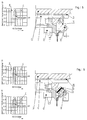
- Fig. 1 the receiving half of the sensor device is shown, which is to be added in principle symmetrically to the center line 7 shown as a break line.
- the sensor device comprises an optical body 1 which has two parallel boundary surfaces 8 and 9 as well as an inlet coupling surface (not shown) and an outlet coupling surface 10.
- the exit coupling surface closes off a converging lens 11, so that a convergent light beam emerges.
- the converging lens 11 and an execution piece 12 for the radiation can be formed in one piece with the optic body 1 or in multiple pieces.
- the exit axis 13 of the light beam is inclined to the interface 8. The angle of inclination is preferably 45 °. In any case, the exit axis forms an angle of 90 ° with the entry axis, not shown.
- the optic body sits in a base 2 for the mechanical mounting of all parts.
- An optoelectronic receiver e.g. aligned a photodiode, a phototransistor or the like.
- the optic body 1 is connected via a transparent coupling medium 5 e.g. a transparent adhesive is connected to the motor vehicle window 6 and optically coupled.
- the motor vehicle window can be a front window, a rear window or another window.
- the light beam emitted by the transmitter is totally reflected within the optic body and reaches the optoelectronic sensor 3 along the exit axis 13.
- the light beam is narrow-band and is indicated in the filter curves by the rectangular working area. When it rains, a more or less strong wetting of the surface of the motor vehicle window occurs. This affects the amount of reflection. This is detected by the measurement.
- modulation of the light beam can reduce interference, it is precisely in the visible range that interference from daylight is very large, so that no precise measurement is possible.
- the invention therefore provides at least two filters 4, which are indicated in FIG. 1.
- the filter effect is explained using the associated filter curves.
- the upper filter curve for FIG. 1 shows the line-shaped, narrow-band transmission light bundle as the working area.
- the filter 4 as a coating or vapor deposition of the outlet coupling surface 10 is a bandpass filter, the transmission curve 4 'is indicated.
- the upper edge of the conveyor belt ends with the upper end of the work area.
- the bottom edge lies outside of the representation, which is not expressly emphasized in the following.
- the optical body 1 is used as a second filter.
- the optical body 1 represents a bandpass filter with the pass curve 1 '.
- the lower edge of the pass band of the pass curve 1' corresponds approximately to the lower edge of the working area.
- the pass curves have an overlap area that essentially coincides with the working area.
- the exit bundle is thus essentially narrowed onto the working belt. Radiation outside the working band is shielded. It is particularly advantageous if the pass band is in the range of approximately 650 to 750 ⁇ m.
- the filter 4 is designed as an interference filter with the filter curve 4 ′′.
- the arrangement is otherwise unchanged.
- the exit bundle is also restricted to the work area.
- the optic body 1 and the execution piece 12 with the converging lens 11 are formed in two parts.
- the optic body 1 acts through optically active additives as a bandpass filter with the pass curve 1 '.
- the execution piece 12 also acts as a bandpass filter, but with the pass curve 12 '.
- the optical body 1 and the receiver 3 are each designed as a bandpass filter.
- the corresponding filter curves 1 'and 3' are shown.
- One edge of the pass band lies on one side of the working area so that the overlap area coincides with the working area.
- the optical body 1 is designed as a bandpass filter with the filter curve 1 '.
- a filter 14 combined with the receiver 3 is designed as a bandpass filter with the filter curve 14 'or as an interference filter with the filter curve 14' '.
- the optical body 1 is designed as a bandpass filter with the filter curve 1 '.
- a filter 15 with the filter curve 15 ' is assigned to the receiver 3.
- the optical body 1 is also designed as a bandpass filter with the filter curve 1 '.
- a filter 15 is provided on a holder 16 for the receiver 3.
- the filter 15 can be designed as a bandpass filter with the filter curve 15 'or as an interference filter with the filter curve 15''.
- the optical body 1 and the coupling medium 5 are each designed as a bandpass filter with the filter curve 1 'and 5'.
Landscapes
- Engineering & Computer Science (AREA)
- Mechanical Engineering (AREA)
- Automation & Control Theory (AREA)
- General Health & Medical Sciences (AREA)
- Analytical Chemistry (AREA)
- Biochemistry (AREA)
- Physics & Mathematics (AREA)
- General Physics & Mathematics (AREA)
- Immunology (AREA)
- Pathology (AREA)
- Chemical & Material Sciences (AREA)
- Life Sciences & Earth Sciences (AREA)
- Health & Medical Sciences (AREA)
- Investigating Or Analysing Materials By Optical Means (AREA)
- Photometry And Measurement Of Optical Pulse Characteristics (AREA)
Abstract
Description
- Die Erfindung betrifft eine optoelektronische Sensoreinrichtung zur Erfassung des Benetzungsgrades einer transparenten Kraftfahrzeugscheibe mit Niederschlag, wobei ein zwei parallele Grenzflächen und zwei einander gegenüberstehende entgegengesetzt geneigte Koppelflächen aufweisender Optikkörper vorhanden ist, dessen eine Grenzfläche optisch mit der Kraftfahrzeugscheibe gekoppelt ist und dessen Eintrittskoppelfläche mit einem optischen Sender und dessen Austrittskoppelfläche mit einem optischen Empfänger gekoppelt ist.
- Eine derartige Sensoreinrichtung ist aus der DE-PS 33 14 770 C2 bekannt. Diese Einrichtung nutzt die Änderung des Winkels der Totalreflexion in Abhängigkeit von der Benetzung der Kraftfahrzeugscheibe aus. Da die Empfindlichkeitskurve des Empfängers von derjenigen des Senders abweicht, macht sich störende Strahlung stark bemerkbar. Dieses gilt besonders für den Bereich der sichtbaren Wellenlängen.
- Aufgabe der Erfindung ist die möglichste Einschränkung des Austrittsbündels auf den Arbeitshereich des Senders.
- Diese Aufgabe wird nach der Erfindung dadurch gelöst, daß in dem Strahlengang mindestens zwei Filter angeordnet sind, deren Durchlaßbereiche in einem schmalen Frequenzband einen Überlappungsbereich haben.
- Die Erfindung unterscheidet sich insofern vom Stand der Technik, als das Empfangslichtbündel gerade auf den Arbeitsbereich abgestimmt wird. Damit erreicht man im Arbeitsbereich eine hohe Empfindlichkeit bei herabgesetzten Storeinflüssen.
- Eine besonders gute Abstimmung auf den Arbeitsbereich erhält man dadurch, daß der Überlappungsbereich mit dem Arbeitsbereich des optischen Senders übereinstimmt.
- Störeinflüsse sind besonders gering, wenn der Arbeitsbereich im Spektralbereich von 650 - 750 µm liegt.
- Eine besonders günstige Abschirmung von Störstrahlung ergibt sich dadurch, daß ein Filter als Interferenzfilter ausgebildet ist, dessen Durchlaßbereich im wesentlichen mit dem Arbeitsbereich übereinstimmt.
- Mit einem Bandpaßfilter lassen sich dadurch gute Ergebnisse erzielen, daß mindestens ein Filter als Bandpaßfilter ausgebildet ist, dessen Durchlaßband den Arbeitsbereich einschließt und mit einer Bandkante unmittelbar in Nachbarschaft des Arbeitsbereichs liegt.
- Eine gute Ausblendung mit Bandpaßfiltern ergibt sich dadurch, daß beide Filter als Bandpaßfilter ausgebildet sind, deren Durchlaßbereiche des sichtabren Spektrums einerseits an den Arbeitsbereich im langwelligen Bereich und andererseits an den Arbeitsbereich im kurzwelligen Bereich anschließen.
- Ein wirkungsvoller und wirtschaftlicher Aufbau wird dadurch erzielt, daß das eine Filter durch den Optikkörper realisiert ist.
- Die Eigenschaften des Optikkörpers lassen sich dadurch in weitem Umfang beeinflussen, daß der als Filter dienende Optikkörper eine Mischung von Glasmaterialien unterschiedlicher Eigenschatten ist.
- Eine andere wirkungsvolle Möglichkeit wird dadurch erzielt, daß ein Filter durch eine dielektrische Schicht realisiert ist, die auf den Optikkörper durch einen Sputterprozeß aufgebracht ist.
- Eine weitere Möglichkeit der Beeinflussung liegt darin, daß ein Filter durch die zwischen dem Optikkörper und der Kraftahrzeugscheibe befindliche Klebeschicht realisiert ist.
- Eine weitere Möglichkeit der Beeinflussung wird dadurch verwirklicht, daß ein Filter durch ein dem optischen Empfänger zugeordnetes, am Halter des Empfängers vorhandenes Zusatzelement realisiert ist.
- Ausführungsbeispiele der Erfindung werden anhand der Zeichnungen erläutert, in denen darstellen:
- Fig. 1
- einen Schnitt durch den Empfangsteil der Sensoreinrichung sowie zwei Filterkurven,
- Fig. 2
- einen Schnitt sowie eine Filterkurve für ein zweites Ausführungsbeispiel und
- die Fig. 3 bis 7
- entsprechende Darstellungen weiterer Ausführungsbeispiele.
- In Fig. 1 ist die Empfangshälfte der Sensoreinrichtung dargestellt, die im Prinzip symmetrisch zu der als Bruchlinie eingezeichneten Mittellinie 7 zu ergänzen ist. Die Sensoreinrichtung umfaßt einen Optikkörper 1, der zwei parallele Grenzflächen 8 und 9 sowie eine nicht dargestellte Eintrittskoppelfläche und eine Austrittkoppelfläche 10 aufweist. Die Austrittskoppelfläche schließt eine Sammellinse 11 ab, so daß ein konvergentes Lichtbündel austritt. Die Sammellinse 11 und ein Ausführungsstück 12 für die Strahlung können einteilig mit dem Optikkörper 1 oder mehrteilig ausgebildet sein. Die Austrittsachse 13 des Lichbündels ist geneigt zu der Grenzfläche 8. Der Neigungswinkel beträgt vorzugsweise 45°. Jedenfalls bildet die Austrittsachse mit der nicht dargestellten Eintrittsachse einen Winkel von 90°.
- Der Optikkörper sitzt in einem Sockel 2 für die mechanische Halterung aller Teile. Auf die Austrittsachse 13 ist ein optoelektronischer Empfänger 3, z.B. eine Photodiode, ein Phototransistor oder dergleichen ausgerichtet.
- Der Optikkörper 1 ist über ein transparentes Koppelmedium 5 z.B. ein transparentes Klebemittel mit der Kraftfahrzeugscheibe 6 verbunden und optisch gekoppelt. Die Kraftfahrzeugscheibe kann eine Frontscheibe, eine Heckscheibe oder eine andere Scheibe sein.
- Das von dem Sender ausgestrahlte Lichtbündel wird innerhalb des Optikkörper totalreflektiert und erreicht längs der Austrittsachse 13 den optoelektronischen Sensor 3. Das Lichtbündel ist schmalbandig und in den Filterkurven jeweils durch den rechteckigen Arbeitsbereich angegeben. Bei Regen tritt eine mehr oder weniger starke Benetzung der Oberfläche der Kraftfahrzeugscheibe auf. Dadurch wird die Reflexionsanteil beeinflußt. Dieses wird durch die Messung erfaßt. Zwar läßt sich durch Modulation des Lichtbündels eine Reduzierung von Störeinflüssen erreichen, doch gerade im sichtbaren Bereich sind die Störeinflüsse durch Tageslicht sehr groß, so daß keine genaue Messung möglich ist.
- Die Erfindung sieht daher mindestens zwei Filter 4 vor, die in Fig. 1 andeutungsweise dargestellt sind. Die Filterwirkung wird an den jeweils zugehörigen Filterkurven erläutert.
- Die obere Filterkurve zu Fig. 1 zeigt als Arbeitsbereich das linienförmige, schmalbandige Sendelichtbündel. Das Filter 4 als Belag oder Aufdampfung der Austrittskoppelfläche 10 ist ein Bandpaßfilter, dessen Durchlaßkurve 4' angegeben ist. Die Oberkante des Durchlaßbandes schließt mit dem Oberende des Arbeitsbereiches ab. Die Unterkante liegt außernalb der Darstellung, was im Folgenden nicht jeweils ausdrücklich betont wird. Der Optikkörper 1 ist als zweites Filter benutzt. Durch optisch aktive Zusätze stellt der Optikkörper 1 ein Bandpaßfilter mit der Durchlaßkurve 1' dar. Die Unterkante des Durchlaßbandes der Durchlaßkurve 1' stimmt etwa mit der Unterkante des Arbeitsbreiches überein. Die Durchlaßkurven haben einen Überlappungsbereich, der im wesentlichen mit dem Arbeitsbereich übereinstimmt. Somit wird das Austrittsbündel im wesentlichen auf das Arbeitsband eingeengt. Strahlung außerhalb des Arbeitsbandes wird abgeschirmt. Es ist besonders vorteilhaft, wenn das Durchlaßband im Bereich von etwa 650 - 750 µm liegt.
- In der unteren Filterkurve zu Fig. 1 ist das Filter 4 als Interferenzfilter mit der Filterkurve 4'' ausgebildet. Im übrigen ist die Anordnung unverändert. Man erhält ebenfalls eine Einschränkung des Austrittsbündels auf den Arbeitsbereich.
- Bei dem Ausführungsbeispiel der Fig. 2 sind der Optikkörper 1 und das Ausführungsstück 12 mit der Sammellinse 11 zweiteilig ausgebildet. Der Optikkörper 1 wirkt durch optisch aktive Zusätze als Bandpaßfilter mit der Durchlaßkurve 1'. Das Ausführungsstück 12 wirkt ebenfalls als Bandpaßfilter, jedoch mit der Durchlaßkurve 12'.
- Bei dem Ausführungsbeispiel der Fig. 3 sind der Optikkörper 1 und der Empfänger 3 jeweils als Bandpaßfilter ausgebildet. Die entsprechenden Filterkurven 1' und 3' sind eingezeichnet. Jeweils eine Kante des Durchlaßbereiches liegt auf einer Seite des Arbeitsbereiches, so daß der Überlappungsbereich mit dem Arbeitsbereich übereinstimmt.
- Bei dem Ausführungsbeispiel nach Fig. 4 ist der Optikkörper 1 als Bandpaßfilter mit der Filterkurve 1' ausgebildet. Ein mit dem Empfänger 3 kombiniertes Filter 14 ist als Bandpaßfilter mit der Filterkurve 14' oder als Interferenzfilter mit der Filterkurve 14'' ausgebildet.
- Bei dem Ausführungsbeispiel nach Fig. 5 ist der Optikkörper 1 als Bandpaßfilter mit der Filterkurve 1' ausgebildet. Dem Empfänger 3 ist ein Filter 15 mit der Filterkurve 15' zugeordnet.
- Bei dem Ausführungsbeispiel nach Fig. 6 ist ebenfalls der Optikkörper 1 als Bandpaßfilter mit der Filterkurve 1' ausgebildet. Ein Filter 15 ist an einem Halter 16 für den Empfänger 3 vorgesehen. Das Filter 15 kann als Bandpaßfilter mit der Filterkurve 15' oder als Inrerferenzfilter mit der Filterkurve 15'' ausgebildet sein.
- Bei dem Ausführungsbeispiel nach Fig. 7 sind der Optikkörper 1 und das Koppelmedium 5 als Bandpaßfilter jeweils mit der Filterkurve 1' und 5' ausgebildet.
- Zusästzlich zu den dargestellten Filterkombinationen sind andere Filterkombinationen anwendbar.
Claims (11)
- Optoelektronische Sensoreinrichtung zur Erfassung des Benetzungsgrades einer transparenten Kraftfahrzeugscheibe mit Niederschlag, wobei ein zwei parallele Grenzflächen und zwei einander gegenüberstehende entgegengesetzt geneigte Koppelflächen aufweisender Optikkörper vorhanden ist, dessen eine Grenzfläche optisch mit der Kraftfahrzeugscheibe gekoppelt ist und dessen Eintrittskoppelfläche mit einem optischen Sender und dessen Austrittskoppelfläche mit einem optischen Empfänger gekoppelt ist, dadurch gekennzeichnet, daß in dem Strahlengang mindestens zwei Filter (4) angeordnet sind, deren Durchlaßbereiche in einem schmalen Frequenzband einen Überlappungsbereich haben.
- Sensoreinrichtung nach Anspruch 1, dadurch gekennzeichnet, daß der Überlappungsbereich mit dem Arbeitsbereich des optischen Senders übereinstimmt.
- Sensoreinrichtung nach Anspruch 1 oder 2, dadurch gekennzeichnet, daß der Arbeitsbereich im Spektralbereich von 650 - 750 µm liegt.
- Sensoreinrichtung nach einem der Ansprüche 1 bis 3, dadurch gekennzeichnet, daß das eine Filter als Interferenzfilter ausgebildet ist, dessen Durchlaßbereich im wesentlichen mit dem Arbeitsbereich übereinstimmt.
- Sensoreinrichtung nach einem der Ansprüche 1 bis 4, dadurch gekennzeichnet, daß mindestens ein Filter als Bandpaßfilter ausgebildet ist, dessen Durchlaßband den Arbeitsbereich einschließt und mit einer Bandkante unmittelbar in Nachbarschaft des Arbeitsbereichs liegt.
- Sensoreinrichtung nach Anspruch 5, dadurch gekennzeichnet, daß beide Filter als Bandpaßfilter ausgebildet sind, deren Durchlaßbereiche einerseits an den Arbeitsbereich im langwelligen Bereich und andererseits an den Arbeitsbereich im kurzwelligen Bereich anschließen.
- Sensoreinrichtung nach Anspruch 1 oder einem der folgenden, dadurch gekennzeichnet, daß das eine Filter durch den Optikkörper realisiert ist.
- Sensoreinrichtung nach Anspruch 1 oder einem der folgenden, dadurch gekennzeichnet, daß der als Filter dienende Optikkörper eine Mischung von Glasmaterialien unterschiedlicher Eigenschaften ist.
- Sensoreinrichtung nach Anspruch 1 oder einem der folgenden, dadurch gekennzeichnet, daß ein Filter durch eine dielektrische Schicht realisiert ist, die auf den Optikkörper durch einen Sputterprozeß aufgebracht ist.
- Sensoreinrichtung nach Anspruch 1 oder einem der folgenden, dadurch gekennzeichnet, daß ein Filter durch die zwischen dem Optikkörper und der Kraftahrzeugscheibe befindliche Klebeschicht realisiert ist.
- Sensoreinrichtung nach Anspruch 1 oder einem der folgenden, dadurch gekennzeichnet, daß ein Filter durch ein dem optischen Empfänger zugeordnetes, am Halter des Empfängers vorhandenes Zusatzelement realisiert ist.
Applications Claiming Priority (2)
| Application Number | Priority Date | Filing Date | Title |
|---|---|---|---|
| DE4424454 | 1994-07-12 | ||
| DE4424454A DE4424454C2 (de) | 1994-07-12 | 1994-07-12 | Optoelektronische Sensoreinrichtung zur Erfassung des Benetzungsgrades einer transparenten Kraftfahrzeugscheibe mit Niederschlag |
Publications (2)
| Publication Number | Publication Date |
|---|---|
| EP0705745A1 true EP0705745A1 (de) | 1996-04-10 |
| EP0705745B1 EP0705745B1 (de) | 1998-11-04 |
Family
ID=6522878
Family Applications (1)
| Application Number | Title | Priority Date | Filing Date |
|---|---|---|---|
| EP95109797A Expired - Lifetime EP0705745B1 (de) | 1994-07-12 | 1995-06-23 | Optoelektronische Sensoreinrichtung zur Erfassung des Benetzungsgrades einer transparenten Kraftfahrzeugscheibe mit Niederschlag |
Country Status (5)
| Country | Link |
|---|---|
| US (1) | US5818600A (de) |
| EP (1) | EP0705745B1 (de) |
| BR (1) | BR9502340A (de) |
| DE (2) | DE4424454C2 (de) |
| ES (1) | ES2126811T3 (de) |
Cited By (1)
| Publication number | Priority date | Publication date | Assignee | Title |
|---|---|---|---|---|
| US6020704A (en) * | 1997-12-02 | 2000-02-01 | Valeo Electrical Systems, Inc. | Windscreen sensing and wiper control system |
Families Citing this family (18)
| Publication number | Priority date | Publication date | Assignee | Title |
|---|---|---|---|---|
| US7019275B2 (en) * | 1997-09-16 | 2006-03-28 | Gentex Corporation | Moisture sensor and windshield fog detector |
| US6681163B2 (en) | 2001-10-04 | 2004-01-20 | Gentex Corporation | Moisture sensor and windshield fog detector |
| US5923027A (en) | 1997-09-16 | 1999-07-13 | Gentex Corporation | Moisture sensor and windshield fog detector using an image sensor |
| DE19713910C1 (de) * | 1997-04-04 | 1998-07-30 | Kostal Leopold Gmbh & Co Kg | Optoelektronische Sensoreinrichtung |
| DE19713909C1 (de) * | 1997-04-04 | 1998-11-12 | Kostal Leopold Gmbh & Co Kg | Optoelektronische Sensoreinrichtung |
| DE19749331A1 (de) * | 1997-11-07 | 1999-05-20 | Kostal Leopold Gmbh & Co Kg | Verfahren zum Detektieren von auf einer Windschutzscheibe befindlichen Objekten sowie Vorrichtung |
| DE19815748C5 (de) * | 1998-04-08 | 2008-02-28 | Robert Bosch Gmbh | Sensoreinrichtung zur Erfassung einer Benetzung einer Scheibe |
| EP1147031B1 (de) | 1999-01-25 | 2011-12-28 | Gentex Corporation | Steuerung von fahrzeuggeräten mit halbleiterlichtsensoren |
| US6313457B1 (en) | 1999-01-25 | 2001-11-06 | Gentex Corporation | Moisture detecting system using semiconductor light sensor with integral charge collection |
| DE10009992C2 (de) * | 2000-03-01 | 2002-04-11 | Kostal Leopold Gmbh & Co Kg | Filtereinrichtung für einen optoelektronischen Sensor |
| JP3437843B2 (ja) | 2001-07-06 | 2003-08-18 | 沖電気工業株式会社 | 絶縁膜の形成方法及び集積回路の製造方法 |
| US6617564B2 (en) | 2001-10-04 | 2003-09-09 | Gentex Corporation | Moisture sensor utilizing stereo imaging with an image sensor |
| FR2944143A1 (fr) * | 2009-04-02 | 2010-10-08 | Photowatt Internat | Detection de salissure |
| US8620523B2 (en) | 2011-06-24 | 2013-12-31 | Gentex Corporation | Rearview assembly with multiple ambient light sensors |
| EP2740003B1 (de) | 2011-08-05 | 2017-06-14 | Gentex Corporation | Optische baugruppe für einen lichtsensor |
| DE102011081365A1 (de) * | 2011-08-23 | 2013-02-28 | Robert Bosch Gmbh | Verfahren zum Aufbereiten eines Lichtsignals zur Regenerkennung in einem Fahrzeug und Verfahren zur Regenerkennung in einem Fahrzeug |
| US9207116B2 (en) | 2013-02-12 | 2015-12-08 | Gentex Corporation | Light sensor |
| US9870753B2 (en) | 2013-02-12 | 2018-01-16 | Gentex Corporation | Light sensor having partially opaque optic |
Citations (6)
| Publication number | Priority date | Publication date | Assignee | Title |
|---|---|---|---|---|
| DE3314770C2 (de) | 1983-04-23 | 1987-11-12 | Sidler Gmbh & Co, 7400 Tuebingen, De | |
| EP0299606A1 (de) * | 1987-07-15 | 1989-01-18 | Peter A. Hochstein | Elektrooptisches Abfühlen von Feuchtigkeit auf Windschutzscheiben |
| US4867561A (en) * | 1986-08-22 | 1989-09-19 | Nippondenso Co., Ltd. | Apparatus for optically detecting an extraneous matter on a translucent shield |
| US4920257A (en) * | 1986-10-09 | 1990-04-24 | Rupert Fuerthbauer | Light filter with automatic regulationof optical transmission |
| US4960996A (en) * | 1989-01-18 | 1990-10-02 | Hochstein Peter A | Rain sensor with reference channel |
| DE4006174C1 (de) * | 1990-02-28 | 1991-07-25 | Leopold Kostal Gmbh & Co Kg, 5880 Luedenscheid, De |
Family Cites Families (2)
| Publication number | Priority date | Publication date | Assignee | Title |
|---|---|---|---|---|
| JPS61116645A (ja) * | 1984-11-09 | 1986-06-04 | Nippon Denso Co Ltd | ウインドシ−ルドワイパ自動制御装置のための液体検出器 |
| FR2591167A1 (fr) * | 1985-07-11 | 1987-06-12 | Questiaux Stephane | Dispositifs de commande d'essuie-glaces, et de facon plus generale les detecteurs de transparence d'une paroi |
-
1994
- 1994-07-12 DE DE4424454A patent/DE4424454C2/de not_active Expired - Fee Related
-
1995
- 1995-06-23 EP EP95109797A patent/EP0705745B1/de not_active Expired - Lifetime
- 1995-06-23 DE DE59504131T patent/DE59504131D1/de not_active Expired - Lifetime
- 1995-06-23 ES ES95109797T patent/ES2126811T3/es not_active Expired - Lifetime
- 1995-07-12 BR BR9502340A patent/BR9502340A/pt not_active IP Right Cessation
- 1995-07-30 US US08/497,144 patent/US5818600A/en not_active Expired - Fee Related
Patent Citations (6)
| Publication number | Priority date | Publication date | Assignee | Title |
|---|---|---|---|---|
| DE3314770C2 (de) | 1983-04-23 | 1987-11-12 | Sidler Gmbh & Co, 7400 Tuebingen, De | |
| US4867561A (en) * | 1986-08-22 | 1989-09-19 | Nippondenso Co., Ltd. | Apparatus for optically detecting an extraneous matter on a translucent shield |
| US4920257A (en) * | 1986-10-09 | 1990-04-24 | Rupert Fuerthbauer | Light filter with automatic regulationof optical transmission |
| EP0299606A1 (de) * | 1987-07-15 | 1989-01-18 | Peter A. Hochstein | Elektrooptisches Abfühlen von Feuchtigkeit auf Windschutzscheiben |
| US4960996A (en) * | 1989-01-18 | 1990-10-02 | Hochstein Peter A | Rain sensor with reference channel |
| DE4006174C1 (de) * | 1990-02-28 | 1991-07-25 | Leopold Kostal Gmbh & Co Kg, 5880 Luedenscheid, De |
Cited By (1)
| Publication number | Priority date | Publication date | Assignee | Title |
|---|---|---|---|---|
| US6020704A (en) * | 1997-12-02 | 2000-02-01 | Valeo Electrical Systems, Inc. | Windscreen sensing and wiper control system |
Also Published As
| Publication number | Publication date |
|---|---|
| US5818600A (en) | 1998-10-06 |
| DE4424454A1 (de) | 1996-01-18 |
| ES2126811T3 (es) | 1999-04-01 |
| EP0705745B1 (de) | 1998-11-04 |
| DE59504131D1 (de) | 1998-12-10 |
| BR9502340A (pt) | 1996-06-18 |
| DE4424454C2 (de) | 1999-08-12 |
Similar Documents
| Publication | Publication Date | Title |
|---|---|---|
| EP0705745B1 (de) | Optoelektronische Sensoreinrichtung zur Erfassung des Benetzungsgrades einer transparenten Kraftfahrzeugscheibe mit Niederschlag | |
| EP0048379B1 (de) | Planare Wellenleiter-Bragg-Gitterstruktur und ihre Verwendung | |
| DE4318114C2 (de) | Sensoreinrichtung | |
| DE69501404T2 (de) | Protonenaustausch-Polarisator mit Ortsfilter zum Verbessern des Polarisationsverhältnisses | |
| EP0006530A1 (de) | Faseroptisches Temperaturmessgerät | |
| DE3903019A1 (de) | Optische farbteiler-anordnung | |
| EP0444520A2 (de) | Sensoreinrichtung | |
| DE69227486T2 (de) | Magnetooptischer Lesekopf | |
| EP0075107B1 (de) | Optischer Isolator | |
| WO2000073771A1 (de) | Verfahren und vorrichtung zum erkennen von fremdstoffen in einem längsbewegten faserverbund | |
| DD292078A5 (de) | Fchelle-polychromator | |
| DE69936402T2 (de) | Feuchtigkeitssensor mit digitaler signalverarbeitungsfilterung | |
| EP0745838B1 (de) | Sichtweitenmessgerät | |
| DE10316514A1 (de) | Vorrichtung zur IR-spektrometrischen Analyse eines festen, flüssigen oder gasförmigen Mediums | |
| DE4133126C2 (de) | Feuchtesensor | |
| DE4025851C2 (de) | ||
| DE3543179A1 (de) | Optischer weg-sensor mit einem filter | |
| DE4329188A1 (de) | Optischer Sensor zur Steuerung einer Scheibenwischeranlage | |
| DE2850701A1 (de) | Optisches lesegeraet fuer einen laserstrahlabtaster | |
| EP1698532B1 (de) | Optischer Sensor mit optimierter Sensitivität | |
| DE102006040813B4 (de) | Laserscanner mit Sende- und Empfangseinrichtung | |
| DE19608650C1 (de) | Vorrichtung zum Erfassen von Benetzungsereignissen auf einer Scheibe | |
| EP0226652B1 (de) | Sensor | |
| DE4336589C1 (de) | Laserleistungsmeßgerät | |
| DE2842231A1 (de) | Mess- und/oder ueberwachungseinrichtung fuer lagerverschleiss |
Legal Events
| Date | Code | Title | Description |
|---|---|---|---|
| PUAI | Public reference made under article 153(3) epc to a published international application that has entered the european phase |
Free format text: ORIGINAL CODE: 0009012 |
|
| AK | Designated contracting states |
Kind code of ref document: A1 Designated state(s): DE ES FR GB IT SE |
|
| 17P | Request for examination filed |
Effective date: 19960502 |
|
| GRAG | Despatch of communication of intention to grant |
Free format text: ORIGINAL CODE: EPIDOS AGRA |
|
| GRAG | Despatch of communication of intention to grant |
Free format text: ORIGINAL CODE: EPIDOS AGRA |
|
| GRAH | Despatch of communication of intention to grant a patent |
Free format text: ORIGINAL CODE: EPIDOS IGRA |
|
| 17Q | First examination report despatched |
Effective date: 19980324 |
|
| GRAH | Despatch of communication of intention to grant a patent |
Free format text: ORIGINAL CODE: EPIDOS IGRA |
|
| GRAA | (expected) grant |
Free format text: ORIGINAL CODE: 0009210 |
|
| AK | Designated contracting states |
Kind code of ref document: B1 Designated state(s): DE ES FR GB IT SE |
|
| PG25 | Lapsed in a contracting state [announced via postgrant information from national office to epo] |
Ref country code: IT Free format text: LAPSE BECAUSE OF FAILURE TO SUBMIT A TRANSLATION OF THE DESCRIPTION OR TO PAY THE FEE WITHIN THE PRE;WARNING: LAPSES OF ITALIAN PATENTS WITH EFFECTIVE DATE BEFORE 2007 MAY HAVE OCCURRED AT ANY TIME BEFORE 2007. THE CORRECT EFFECTIVE DATE MAY BE DIFFERENT FROM THE ONE RECORDED.SCRIBED TIME-LIMIT Effective date: 19981104 |
|
| REF | Corresponds to: |
Ref document number: 59504131 Country of ref document: DE Date of ref document: 19981210 |
|
| GBT | Gb: translation of ep patent filed (gb section 77(6)(a)/1977) |
Effective date: 19990202 |
|
| ET | Fr: translation filed | ||
| REG | Reference to a national code |
Ref country code: ES Ref legal event code: FG2A Ref document number: 2126811 Country of ref document: ES Kind code of ref document: T3 |
|
| PLBE | No opposition filed within time limit |
Free format text: ORIGINAL CODE: 0009261 |
|
| STAA | Information on the status of an ep patent application or granted ep patent |
Free format text: STATUS: NO OPPOSITION FILED WITHIN TIME LIMIT |
|
| 26N | No opposition filed | ||
| REG | Reference to a national code |
Ref country code: FR Ref legal event code: RN |
|
| REG | Reference to a national code |
Ref country code: FR Ref legal event code: FC |
|
| REG | Reference to a national code |
Ref country code: FR Ref legal event code: ST |
|
| REG | Reference to a national code |
Ref country code: GB Ref legal event code: IF02 |
|
| PGFP | Annual fee paid to national office [announced via postgrant information from national office to epo] |
Ref country code: FR Payment date: 20100630 Year of fee payment: 16 Ref country code: ES Payment date: 20100628 Year of fee payment: 16 |
|
| PGFP | Annual fee paid to national office [announced via postgrant information from national office to epo] |
Ref country code: SE Payment date: 20100616 Year of fee payment: 16 Ref country code: GB Payment date: 20100622 Year of fee payment: 16 |
|
| REG | Reference to a national code |
Ref country code: SE Ref legal event code: EUG |
|
| GBPC | Gb: european patent ceased through non-payment of renewal fee |
Effective date: 20110623 |
|
| REG | Reference to a national code |
Ref country code: FR Ref legal event code: ST Effective date: 20120229 |
|
| PG25 | Lapsed in a contracting state [announced via postgrant information from national office to epo] |
Ref country code: FR Free format text: LAPSE BECAUSE OF NON-PAYMENT OF DUE FEES Effective date: 20110630 |
|
| PG25 | Lapsed in a contracting state [announced via postgrant information from national office to epo] |
Ref country code: GB Free format text: LAPSE BECAUSE OF NON-PAYMENT OF DUE FEES Effective date: 20110623 |
|
| PG25 | Lapsed in a contracting state [announced via postgrant information from national office to epo] |
Ref country code: SE Free format text: LAPSE BECAUSE OF NON-PAYMENT OF DUE FEES Effective date: 20110624 |
|
| REG | Reference to a national code |
Ref country code: ES Ref legal event code: FD2A Effective date: 20130531 |
|
| PG25 | Lapsed in a contracting state [announced via postgrant information from national office to epo] |
Ref country code: ES Free format text: LAPSE BECAUSE OF NON-PAYMENT OF DUE FEES Effective date: 20110624 |
|
| PGFP | Annual fee paid to national office [announced via postgrant information from national office to epo] |
Ref country code: DE Payment date: 20140530 Year of fee payment: 20 |
|
| REG | Reference to a national code |
Ref country code: DE Ref legal event code: R071 Ref document number: 59504131 Country of ref document: DE |