EP0705748A1 - Hydraulischer Brennkraftverstärker mit verbesserter Eingangscharakteristik - Google Patents
Hydraulischer Brennkraftverstärker mit verbesserter Eingangscharakteristik Download PDFInfo
- Publication number
- EP0705748A1 EP0705748A1 EP95401900A EP95401900A EP0705748A1 EP 0705748 A1 EP0705748 A1 EP 0705748A1 EP 95401900 A EP95401900 A EP 95401900A EP 95401900 A EP95401900 A EP 95401900A EP 0705748 A1 EP0705748 A1 EP 0705748A1
- Authority
- EP
- European Patent Office
- Prior art keywords
- housing
- control rod
- sleeve
- wall
- sliding
- Prior art date
- Legal status (The legal status is an assumption and is not a legal conclusion. Google has not performed a legal analysis and makes no representation as to the accuracy of the status listed.)
- Granted
Links
- 230000003111 delayed effect Effects 0.000 claims description 8
- 230000000694 effects Effects 0.000 claims description 3
- 230000000750 progressive effect Effects 0.000 abstract 1
- 238000010586 diagram Methods 0.000 description 2
- 230000006870 function Effects 0.000 description 2
- 230000035515 penetration Effects 0.000 description 2
- 230000035807 sensation Effects 0.000 description 2
- 239000007788 liquid Substances 0.000 description 1
- 238000004519 manufacturing process Methods 0.000 description 1
Images


Classifications
-
- B—PERFORMING OPERATIONS; TRANSPORTING
- B60—VEHICLES IN GENERAL
- B60T—VEHICLE BRAKE CONTROL SYSTEMS OR PARTS THEREOF; BRAKE CONTROL SYSTEMS OR PARTS THEREOF, IN GENERAL; ARRANGEMENT OF BRAKING ELEMENTS ON VEHICLES IN GENERAL; PORTABLE DEVICES FOR PREVENTING UNWANTED MOVEMENT OF VEHICLES; VEHICLE MODIFICATIONS TO FACILITATE COOLING OF BRAKES
- B60T13/00—Transmitting braking action from initiating means to ultimate brake actuator with power assistance or drive; Brake systems incorporating such transmitting means, e.g. air-pressure brake systems
- B60T13/10—Transmitting braking action from initiating means to ultimate brake actuator with power assistance or drive; Brake systems incorporating such transmitting means, e.g. air-pressure brake systems with fluid assistance, drive, or release
- B60T13/12—Transmitting braking action from initiating means to ultimate brake actuator with power assistance or drive; Brake systems incorporating such transmitting means, e.g. air-pressure brake systems with fluid assistance, drive, or release the fluid being liquid
-
- B—PERFORMING OPERATIONS; TRANSPORTING
- B60—VEHICLES IN GENERAL
- B60T—VEHICLE BRAKE CONTROL SYSTEMS OR PARTS THEREOF; BRAKE CONTROL SYSTEMS OR PARTS THEREOF, IN GENERAL; ARRANGEMENT OF BRAKING ELEMENTS ON VEHICLES IN GENERAL; PORTABLE DEVICES FOR PREVENTING UNWANTED MOVEMENT OF VEHICLES; VEHICLE MODIFICATIONS TO FACILITATE COOLING OF BRAKES
- B60T13/00—Transmitting braking action from initiating means to ultimate brake actuator with power assistance or drive; Brake systems incorporating such transmitting means, e.g. air-pressure brake systems
- B60T13/10—Transmitting braking action from initiating means to ultimate brake actuator with power assistance or drive; Brake systems incorporating such transmitting means, e.g. air-pressure brake systems with fluid assistance, drive, or release
- B60T13/12—Transmitting braking action from initiating means to ultimate brake actuator with power assistance or drive; Brake systems incorporating such transmitting means, e.g. air-pressure brake systems with fluid assistance, drive, or release the fluid being liquid
- B60T13/14—Transmitting braking action from initiating means to ultimate brake actuator with power assistance or drive; Brake systems incorporating such transmitting means, e.g. air-pressure brake systems with fluid assistance, drive, or release the fluid being liquid using accumulators or reservoirs fed by pumps
- B60T13/142—Systems with master cylinder
- B60T13/143—Master cylinder mechanically coupled with booster
Definitions
- the present invention relates to a hydraulic booster for braking assistance, comprising on the one hand a sealed housing delimited by at least one wall, and on the other hand a control rod mounted with sliding sliding in an opening of this wall and capable, from a rest position, to be pushed into the interior of the housing under the effect of an input force to gradually open a communication between the interior of this housing and an auxiliary pressure source, the pressure delivered by this source exerting on the control rod a reaction opposing the input force.
- Brake booster actuators currently known can be classified in the category of pneumatic servomotors or hydraulic servomotors, depending on whether they use the auxiliary pressure of a gas, traditionally the atmosphere, or that of a liquid.
- the object of the present invention is to propose a hydraulic servomotor offering, to the driver who actuates the brake pedal, a feeling very similar to that offered by a pneumatic servomotor.
- the booster of the invention is essentially characterized in that it comprises, in addition to the elements set out in the preamble above: a cylindrical sleeve interposed between the opening of the wall and the control rod and sliding tightly relative to this opening and to this rod; a stop opposing the sliding of the sleeve towards the outside of the housing; and delayed reaction means for transmitting to the control rod, when it has traveled a non-zero stroke from its rest position, at least part of the force exerted on the sleeve by the pressure prevailing inside the housing .
- the delayed reaction means comprise at least deferred drive means to allow the control rod, when it has traveled a stroke of non-zero length from its rest position, to drive the sleeve to the inside the housing, these deferred drive means being for example essentially constituted by a nut screwed onto a thread of the control rod.
- the delayed reaction means can also include a prestressed spring pressing the stop against the outside of the wall, this spring being able to bear itself, at a distance from the stop on the control rod to return this rod to its rest position.
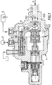
- FIG. 1 which only illustrates the general field of the invention, this relates to a hydraulic brake booster for motor vehicles, essentially comprising a sealed housing 1 delimited by at least one wall 100.
- a control rod 2 is slidably mounted in an opening 101 in this wall so that, from a rest position which is that represented in FIGS. 1 and 2, it can be pushed inside the housing 102 1 under the effect of an input force F, this force being applied by the driver of the vehicle to a brake pedal 200 shown in FIG. 2.
- control rod 2 actuates, inside the housing 1, a lever 3 which controls the position of a drawer 4, the latter gradually opening, as it moves, a communication between the interior 102 of the housing 1 and an auxiliary pressure source such as a hydraulic pump 5.
- the pressure delivered by this source 5, and which is used to actuate a brake motor 6, also exerts, on the control rod 2, a reaction which opposes the input force F.
- the invention is based on the idea which consists in obtaining an evolution of this reaction.
- the booster of the invention comprises (FIG. 2) a cylindrical sleeve 7, a stop 8 and delayed reaction means 9, 10, 70 including at least delayed drive means 9, 70.
- the sleeve 7 is interposed between the opening 101 of the wall 100 and the control rod 2 and slides in leaktight manner with respect to this opening and to this rod.
- the stop 8 has the function of providing resistance to the sliding of the sleeve 7 towards the outside of the housing.
- the deferred drive means have the function of allowing the control rod 2, when it has traveled a stroke of non-zero length from its rest position, to drive the sleeve 7 inside the housing 1.
- the deferred drive means preferably comprise an axial face 70 of the sleeve 7 and a nut 9 screwed onto a thread 20 of the control rod, which allows, by screwing this nut on the rod , to adjust the dead travel M that the control rod 2 will have to perform before the lever 3 opens the communication between the source 5 and the interior 102 of the housing 1.
- the stop 8 may be integral with the wall 100 of the booster.
- the deferred drive means 9, 70 themselves constitute deferred reaction means, which in this case make it possible to transmit to the control rod 2 all the force exerted on the sleeve 7 by the pressure prevailing at inside the box 1 as soon as this sleeve is driven towards the inside of this box by the control rod 2.
- the stop 8 can, as a variant, be simply pressed against the wall 100 of the booster by a pre-stressed spring 10, this spring being capable of acting as an additional means in carrying out a delayed reaction , in a manner which will be more precisely explained with reference to FIG. 3.
- This same spring 10 can also serve to return the control rod 2, one end of this spring pressing on the stop 8, and the other end of this spring pressing on the nut 9, which is axially integral with the rod 2.
- FIG. 3 is a diagram representing the inlet force F on the abscissa and the outlet pressure P on the ordinate of a booster according to the invention, and more particularly of the booster illustrated in FIG. 2.
- This mode of operation is extended on condition that, and as long as, the force exerted by the spring 10 remains sufficient to continue to press the stop 8 against the wall 100, against the force exerted by the internal pressure of the servomotor on the section of the sleeve 7, the axial face 70 of which tends to push back the stop 8.
- the curve shown in FIG. 3 being very close to that which characterizes a pneumatic servomotor, the invention therefore makes it possible to obtain, with a hydraulic servomotor, a pedal feeling very close to that offered by a pneumatic servomotor.
Landscapes
- Engineering & Computer Science (AREA)
- Transportation (AREA)
- Mechanical Engineering (AREA)
- Braking Systems And Boosters (AREA)
- Hydraulic Motors (AREA)
Applications Claiming Priority (2)
| Application Number | Priority Date | Filing Date | Title |
|---|---|---|---|
| FR9411819 | 1994-10-04 | ||
| FR9411819A FR2725175B1 (fr) | 1994-10-04 | 1994-10-04 | Servomoteur hydraulique d'assistance au freinage a caracteristique d'entree modifiee |
Publications (2)
| Publication Number | Publication Date |
|---|---|
| EP0705748A1 true EP0705748A1 (de) | 1996-04-10 |
| EP0705748B1 EP0705748B1 (de) | 1997-12-29 |
Family
ID=9467533
Family Applications (1)
| Application Number | Title | Priority Date | Filing Date |
|---|---|---|---|
| EP19950401900 Expired - Lifetime EP0705748B1 (de) | 1994-10-04 | 1995-08-17 | Hydraulischer Brennkraftverstärker mit verbesserter Eingangscharakteristik |
Country Status (4)
| Country | Link |
|---|---|
| EP (1) | EP0705748B1 (de) |
| DE (1) | DE69501307T2 (de) |
| ES (1) | ES2110820T3 (de) |
| FR (1) | FR2725175B1 (de) |
Citations (3)
| Publication number | Priority date | Publication date | Assignee | Title |
|---|---|---|---|---|
| FR2539366A1 (fr) * | 1983-01-14 | 1984-07-20 | Bosch Gmbh Robert | Maitre-cylindre tandem hydraulique a deux circuits |
| FR2559724A1 (fr) | 1984-02-22 | 1985-08-23 | Dba | Dispositif generateur de pression de freinage pour installation de freinage a double circuit |
| US5036665A (en) * | 1990-11-29 | 1991-08-06 | Allied-Signal Inc. | Hydraulic brake booster |
-
1994
- 1994-10-04 FR FR9411819A patent/FR2725175B1/fr not_active Expired - Fee Related
-
1995
- 1995-08-17 EP EP19950401900 patent/EP0705748B1/de not_active Expired - Lifetime
- 1995-08-17 ES ES95401900T patent/ES2110820T3/es not_active Expired - Lifetime
- 1995-08-17 DE DE1995601307 patent/DE69501307T2/de not_active Expired - Fee Related
Patent Citations (4)
| Publication number | Priority date | Publication date | Assignee | Title |
|---|---|---|---|---|
| FR2539366A1 (fr) * | 1983-01-14 | 1984-07-20 | Bosch Gmbh Robert | Maitre-cylindre tandem hydraulique a deux circuits |
| FR2559724A1 (fr) | 1984-02-22 | 1985-08-23 | Dba | Dispositif generateur de pression de freinage pour installation de freinage a double circuit |
| US4641497A (en) | 1984-02-22 | 1987-02-10 | Societe Anonyme D.B.A. | Device for generating braking pressure for a braking installation with twin circuits |
| US5036665A (en) * | 1990-11-29 | 1991-08-06 | Allied-Signal Inc. | Hydraulic brake booster |
Also Published As
| Publication number | Publication date |
|---|---|
| ES2110820T3 (es) | 1998-02-16 |
| DE69501307D1 (de) | 1998-02-05 |
| FR2725175B1 (fr) | 1996-10-31 |
| EP0705748B1 (de) | 1997-12-29 |
| DE69501307T2 (de) | 1998-04-16 |
| FR2725175A1 (fr) | 1996-04-05 |
Similar Documents
| Publication | Publication Date | Title |
|---|---|---|
| FR2670733A1 (fr) | Mecanisme de transmission d'une force de reaction pour servo-frein. | |
| EP0939713B1 (de) | Hilfskraftbremsvorrichtung mit variablem verstärkerverhältnis und verringerter hysterese | |
| FR2998240A1 (fr) | Servofrein electrique | |
| EP0156666A1 (de) | Bremskraftregler | |
| WO1994007722A1 (fr) | Dispositif de freinage assiste a reaction hydraulique ralentie | |
| EP0340059B1 (de) | Bremskraftverstärker mit einstellbarem Schwellenwert | |
| WO1994000325A1 (fr) | Dispositif de commande a clapet pour servomoteur pneumatique | |
| EP0705748B1 (de) | Hydraulischer Brennkraftverstärker mit verbesserter Eingangscharakteristik | |
| EP0915791B1 (de) | Bremskraftverstärker mit hydraulischer reaktion und mit grösserer sicherheit | |
| EP0779870B1 (de) | Pneumatischer bremskraftverstärker | |
| EP0939715B1 (de) | Hilfskraftunterstütztes bremssystem mit verbesserter hydraulischer reaktion | |
| WO1999062749A1 (fr) | Servomoteur pneumatique a disque de reaction flottant et a reaction dynamiquement annulable | |
| EP0730538B1 (de) | Bremsvorrichtung mit maskiertem hub und gleichbleibender verstärkung | |
| FR2729354A1 (fr) | Dispositif de freinage assiste a course reduite | |
| EP0991555B1 (de) | Hauptzylinder mit hydraulisch dynamischer reaktion geregelt durch einen querschnittsunterschied | |
| WO1999000285A1 (fr) | Maitre-cylindre a reaction hydraulique dynamique et a piston flottant | |
| EP1225112B1 (de) | Bremskraftverstärker mit zwei Verstärkungsverhältnissen für Kraftfahrzeuge | |
| FR2760218A1 (fr) | Dispositif de freinage a zone de fragilite controlee | |
| EP0615501B1 (de) | Hilfskraftlenkung mit automatischem spielausgleich | |
| EP0449703B1 (de) | Verfahren zum Regeln des Schwellenwertes an einem Bremskraftverstärker | |
| FR2700513A1 (fr) | Dispositif de freinage assisté à réaction mixte et course masquée. | |
| FR2473972A1 (fr) | Regulateur de pression jumele, pour installation de freinage hydraulique | |
| FR2595638A1 (fr) | Dispositif pour la regulation de la traction d'un vehicule automobile | |
| FR2738790A1 (fr) | Valve d'assistance a depression interchangeable |
Legal Events
| Date | Code | Title | Description |
|---|---|---|---|
| PUAI | Public reference made under article 153(3) epc to a published international application that has entered the european phase |
Free format text: ORIGINAL CODE: 0009012 |
|
| 17P | Request for examination filed |
Effective date: 19950822 |
|
| AK | Designated contracting states |
Kind code of ref document: A1 Designated state(s): DE ES FR GB IT |
|
| RAP1 | Party data changed (applicant data changed or rights of an application transferred) |
Owner name: BOSCH SYSTEMES DE FREINAGE |
|
| GRAG | Despatch of communication of intention to grant |
Free format text: ORIGINAL CODE: EPIDOS AGRA |
|
| GRAG | Despatch of communication of intention to grant |
Free format text: ORIGINAL CODE: EPIDOS AGRA |
|
| GRAH | Despatch of communication of intention to grant a patent |
Free format text: ORIGINAL CODE: EPIDOS IGRA |
|
| 17Q | First examination report despatched |
Effective date: 19970609 |
|
| GRAH | Despatch of communication of intention to grant a patent |
Free format text: ORIGINAL CODE: EPIDOS IGRA |
|
| GRAA | (expected) grant |
Free format text: ORIGINAL CODE: 0009210 |
|
| AK | Designated contracting states |
Kind code of ref document: B1 Designated state(s): DE ES FR GB IT |
|
| GBT | Gb: translation of ep patent filed (gb section 77(6)(a)/1977) |
Effective date: 19971229 |
|
| ITF | It: translation for a ep patent filed | ||
| REF | Corresponds to: |
Ref document number: 69501307 Country of ref document: DE Date of ref document: 19980205 |
|
| REG | Reference to a national code |
Ref country code: ES Ref legal event code: FG2A Ref document number: 2110820 Country of ref document: ES Kind code of ref document: T3 |
|
| PLBE | No opposition filed within time limit |
Free format text: ORIGINAL CODE: 0009261 |
|
| STAA | Information on the status of an ep patent application or granted ep patent |
Free format text: STATUS: NO OPPOSITION FILED WITHIN TIME LIMIT |
|
| 26N | No opposition filed | ||
| REG | Reference to a national code |
Ref country code: GB Ref legal event code: IF02 |
|
| PGFP | Annual fee paid to national office [announced via postgrant information from national office to epo] |
Ref country code: DE Payment date: 20081024 Year of fee payment: 14 |
|
| PGFP | Annual fee paid to national office [announced via postgrant information from national office to epo] |
Ref country code: FR Payment date: 20090819 Year of fee payment: 15 Ref country code: ES Payment date: 20090821 Year of fee payment: 15 |
|
| PGFP | Annual fee paid to national office [announced via postgrant information from national office to epo] |
Ref country code: GB Payment date: 20090821 Year of fee payment: 15 |
|
| PGFP | Annual fee paid to national office [announced via postgrant information from national office to epo] |
Ref country code: IT Payment date: 20090825 Year of fee payment: 15 |
|
| PG25 | Lapsed in a contracting state [announced via postgrant information from national office to epo] |
Ref country code: DE Free format text: LAPSE BECAUSE OF NON-PAYMENT OF DUE FEES Effective date: 20100302 |
|
| GBPC | Gb: european patent ceased through non-payment of renewal fee |
Effective date: 20100817 |
|
| REG | Reference to a national code |
Ref country code: FR Ref legal event code: ST Effective date: 20110502 |
|
| PG25 | Lapsed in a contracting state [announced via postgrant information from national office to epo] |
Ref country code: IT Free format text: LAPSE BECAUSE OF NON-PAYMENT OF DUE FEES Effective date: 20100817 |
|
| PG25 | Lapsed in a contracting state [announced via postgrant information from national office to epo] |
Ref country code: FR Free format text: LAPSE BECAUSE OF NON-PAYMENT OF DUE FEES Effective date: 20100831 |
|
| PG25 | Lapsed in a contracting state [announced via postgrant information from national office to epo] |
Ref country code: GB Free format text: LAPSE BECAUSE OF NON-PAYMENT OF DUE FEES Effective date: 20100817 |
|
| REG | Reference to a national code |
Ref country code: ES Ref legal event code: FD2A Effective date: 20111019 |
|
| PG25 | Lapsed in a contracting state [announced via postgrant information from national office to epo] |
Ref country code: ES Free format text: LAPSE BECAUSE OF NON-PAYMENT OF DUE FEES Effective date: 20100818 |