EP0705787A1 - Serviceeinrichtung an Arbeitsfahrzeugen - Google Patents
Serviceeinrichtung an Arbeitsfahrzeugen Download PDFInfo
- Publication number
- EP0705787A1 EP0705787A1 EP95850174A EP95850174A EP0705787A1 EP 0705787 A1 EP0705787 A1 EP 0705787A1 EP 95850174 A EP95850174 A EP 95850174A EP 95850174 A EP95850174 A EP 95850174A EP 0705787 A1 EP0705787 A1 EP 0705787A1
- Authority
- EP
- European Patent Office
- Prior art keywords
- cabin
- piston
- tilting
- movement
- piston rod
- Prior art date
- Legal status (The legal status is an assumption and is not a legal conclusion. Google has not performed a legal analysis and makes no representation as to the accuracy of the status listed.)
- Granted
Links
- 238000013016 damping Methods 0.000 claims description 7
- 108010066057 cabin-1 Proteins 0.000 description 2
- 230000005484 gravity Effects 0.000 description 2
- 239000010720 hydraulic oil Substances 0.000 description 2
- 239000003921 oil Substances 0.000 description 2
- 230000003213 activating effect Effects 0.000 description 1
- 238000007796 conventional method Methods 0.000 description 1
- 238000011161 development Methods 0.000 description 1
- 238000003780 insertion Methods 0.000 description 1
- 230000037431 insertion Effects 0.000 description 1
- 238000005259 measurement Methods 0.000 description 1
- 230000008439 repair process Effects 0.000 description 1
Images

Classifications
-
- B—PERFORMING OPERATIONS; TRANSPORTING
- B62—LAND VEHICLES FOR TRAVELLING OTHERWISE THAN ON RAILS
- B62D—MOTOR VEHICLES; TRAILERS
- B62D33/00—Superstructures for load-carrying vehicles
- B62D33/06—Drivers' cabs
- B62D33/063—Drivers' cabs movable from one position into at least one other position, e.g. tiltable, pivotable about a vertical axis, displaceable from one side of the vehicle to the other
- B62D33/067—Drivers' cabs movable from one position into at least one other position, e.g. tiltable, pivotable about a vertical axis, displaceable from one side of the vehicle to the other tiltable
-
- B—PERFORMING OPERATIONS; TRANSPORTING
- B66—HOISTING; LIFTING; HAULING
- B66F—HOISTING, LIFTING, HAULING OR PUSHING, NOT OTHERWISE PROVIDED FOR, e.g. DEVICES WHICH APPLY A LIFTING OR PUSHING FORCE DIRECTLY TO THE SURFACE OF A LOAD
- B66F9/00—Devices for lifting or lowering bulky or heavy goods for loading or unloading purposes
- B66F9/06—Devices for lifting or lowering bulky or heavy goods for loading or unloading purposes movable, with their loads, on wheels or the like, e.g. fork-lift trucks
- B66F9/075—Constructional features or details
- B66F9/07545—Overhead guards
Definitions
- this object is solved by making the cabin part of the truck further tiltable in addition to the movement that can be carried out during lifting work.
- the cabin is so to say tilted as a lid and allows free access to the components mounted on the chassis straight from above while the components in the cabin part are accessible from the actual underside that in the uptilted position will be essentially vertical.
- no panels has to be dismounted and mounted and the risk for deforming of panels or the like due to a slight misalignment on mounting is eliminated.
- the service time can be shortened since the entire inner of the truck is quickly accessible in one quickly executed step, namely the tilting upwards of the cabin.
- the same cylinder that takes care of the tilting movement during lifting work can be used to lift the cabin up past its uppermost working position after freeing of a lock. In this way the service tilting is achievable without a lot of extra means requiring location in the truck and also this reduces the cost.
- the cost may be reduced further by the use of a comparatively short cylinder only capable of lifting the cabin up to a position in the vicinity of the position where the cabin balances on its bearings.
- the piston rod of the tilting cylinder may be hollow and into the inner of this a pulling rod extends, that is freely movable between an inserted and an extended position.
- the pull rod may for instance in its inner end carry an end position damper in the shape of a piston arranged in a cylinder that is freely movable, but in a degree corresponding to the desired damping is sealed relative its piston rod respectively closed in the other end.
- the piston is maximally inserted into the cylinder, the friction of the cylinder and the piston holding them in this position until the cylinder abuts the movement limit for the extension.
- the air is compressed and the contact between the piston and the cylinder dampens the contact when the air leaks over to the other side of the piston and the cylinder chamber on that side.
- the movement is ended and the damping of the return movement has been prepared by the damping air chamber being on the other side of the piston.
- the friction of the piston relative the cylinder should for the functioning of the simple damper above be greater than that between the cylinder and the enclosing hole in the piston rod of the tilting cylinder.
- the pulling rod may in its inner end include piston means that cooperate with the enclosing hole in the piston rod so that a damping piston is obtained securing a damped movement for the service uptilting and the lowering of the cabin.
- the cabin When service has well taken place the cabin is by hand brought back over the balanced position to the position where the pulling rod is fully inserted into the piston rod. Since the cabin can be gripped at its upper rear roof edge a long lever is achieved making the movement easier even if the cabin in itself is heavy. By then releasing the oil outlet from the cylinder chamber of the cabin tilt cylinder the cabin can by its own weight sink down towards its working interval at lifting. The normal working area of the piston movement is once again secured or restricted and the cabin is again in its working position or area.
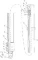
- FIG. 1 schematically shows a truck cabin seen from the side and fig 2 an hydraulic piston for the lifting/tilting movement.
- the truck shown schematically in fig 1 has a cabin 1 which is shown i full line in its lower most position.
- a hydraulic piston is arranged to tilt the cabin with the front end of the cabin (in relation to the driver) upwards so that the driver is inclined or tilted rearward when loads are lifted high to make it easier for the driver to keep the forks and load in sight.
- the cabin is swung around a swivel bearing at the rear of the truck.
- the upper most working position of the cabin is mechanically defined by and end position stop or lock.
- This end position stop is constituted by a block with a T-shaped cross section that through a slot in the cabin wall at the legs of the driver grips into and runs in a protecting channel.
- the T-shaped position stop comes in the in the upper end position of the tilting movement in contact with a stop or lock that against the action of a spring can be brought out of the channel.
- the lock is arranged with a chamfered edge so that it at an opposite lowering movement of the T-piece can be lifted and passed by this so that the cabin after executed service can return to its working area without manual influence on the lock.
- the T-piece together with the cooperating channel also serves as an efficient guide for the movement of the cabin so that there is no risk of the side panels of cabin and truck body deforming each other even if a tight fit is used.
- the hydraulic cylinder can after the freeing of the lock be activated by its ordinary control or by an additional control for the service uptilting of the cabin.
- the piston When the piston then reaches its fully extended position the cabin has reached its middle, with point dashed lines drawn position with an uptilting corresponding to about 45° from the lowest position of the cabin. In this position the cabin 1 is uptilted to such an extant at it is situated close to an upper balance position of the uptilting movement. The force necessary in this position to move the cabin further is therefor comparatively small.
- the cabin is connected to the tilting piston rod via a pull rod movable inside the hollow piston rod between a fully inserted position and an extracted position were stop means in the inner end of the pull rod are in contact with other stop means in the outer end of the piston rod, preventing the pull rod from being drawn out of the piston rod.
- the free movement of the pull rod in the piston rod allows the cabin to be tilted manually from the almost balanced position to a 45° uptilted position of the cabin were further tilting is stopped by the stop means on pull rod and piston rod. This last tilting of the cabin is done entirely manually until the cabin has reached the extreme clockwise position in Fig 1 with the rear wall of the cabin essentially horizontally. In this position a god accessibility is secured to the entire inner of the truck.
- the cabin is by hand swung back upwards and forwards until the pull rod once again is entirely inserted into the piston rod.
- the center of gravity for the cabin is now again in front of the swing axis for the tilting movement and by releasing the outlet from the piston the cabin will be lowered down towards its work angle interval at lifting and the upper end position stop is passed, then once again to become active.
- the hydraulic cylinder 2 is built in the way that is shown in fig 2 with a welded on swing bracket 5 with which the cylinder is pivotally mounted in the chassis of the truck.
- the piston rod 3 is displaceably moveable between a completely inserted position and an extended position where a wire located in a recess in the piston rod will abut against a stop on the top nut 11 of the cylinder.
- the top nut seals 9 and 10 and a scraper 8 are arranged and in the inner end of the piston in addition to the stop wire a guide band is arranged around the piston guiding this in the inner of the cylinder preventing metallic contact between cylinder and piston rod.
- the inner space of the cylinder is connected to suitable control means for the feeding, draining and enclosing of hydraulic oil via a hydraulic connection 18 in the bottom end 16.
- the piston rod 3 is in its lower end closed by a bottom 17 so that the piston rod constitutes the piston.
- the pulling rod 4 is displaceable in such a way that the piston rod in its upper end is provided with a bushing 7 threaded in the outer end of the piston rod, in which bushing the piston is slidable.
- an abutment disc 13 is threaded fast between the end of the rod and a bolt threaded in the rod.
- the abutment disc 13 also serves as a guide for the inner end of the pull rod so that this slides centrally in the hole in the piston rod. When the rod is fully extended the abutment disc 13 abuts against the inner end of the bushing 7.
- a fastening lug 6 is arranged for the fastening of the hydraulic cylinder device to the cabin.
- the tilt swing axis 19 of the tiltable cabin in the chassis of the truck is located at the rear of the cabin so that a maximum of free excess to the inner of the machine is obtained.
- the advantage is obtained that still in the about 45° uptilted position corresponding to the end of the stroke of the piston the point of gravity of the driver as well as that of the cabin will be situated in front of the tilt swing axis 19. This means that even if one through negligence would forget to lock the limiting means for the cabin movement or if these break the hydraulic system can not lift the cabin higher than shortly before the balanced position.
- the described device does thus not only mean a simplified and therefor cost reduced piston means for the tilting of cabin and driver at use as well as the uptilting of the cabin at service but prevent also an undesirable over tilting of cabin and driver to the service position if one should forget to secure the cabin movement or if this lock should be damaged and come out function.
- This also means that even for this case the cabin can always be returned to its horizontal lower position by its own and the drivers weight and pressing away the oil in the hydraulic cylinder.
- the hydraulics cylinder does not need to be of the double action type.
- the cabin can be lowered by the opening of a valve letting out hydraulic oil.
- this valve is electrically controlled and with the activating control button or buttons placed in such a way that the user impossible can be caught between cabin and truck body at the lowering of the cabin, for instance these controls may be located at the rear edge of the cabin roof.
- brackets for the side panels of the truck in the lower part as well as in the upper part, that is the cabin, on the inside. This does not only mean the possibility of an improved appearance but reduces also the risk of protruding bolts, screws, rivets or alike catching in gods or person.
- the pull rod automatically guides the parts back to their previous position, even if the bearings become worn or have a great play.
Landscapes
- Engineering & Computer Science (AREA)
- Transportation (AREA)
- Structural Engineering (AREA)
- Mechanical Engineering (AREA)
- Combustion & Propulsion (AREA)
- Civil Engineering (AREA)
- Chemical & Material Sciences (AREA)
- Life Sciences & Earth Sciences (AREA)
- Geology (AREA)
- Component Parts Of Construction Machinery (AREA)
- Forklifts And Lifting Vehicles (AREA)
- Actuator (AREA)
- Body Structure For Vehicles (AREA)
Applications Claiming Priority (2)
| Application Number | Priority Date | Filing Date | Title |
|---|---|---|---|
| SE9403400 | 1994-10-07 | ||
| SE9403400A SE510807C2 (sv) | 1994-10-07 | 1994-10-07 | Tiltanordning vid truckhytt |
Publications (2)
| Publication Number | Publication Date |
|---|---|
| EP0705787A1 true EP0705787A1 (de) | 1996-04-10 |
| EP0705787B1 EP0705787B1 (de) | 2000-02-02 |
Family
ID=20395516
Family Applications (1)
| Application Number | Title | Priority Date | Filing Date |
|---|---|---|---|
| EP19950850174 Expired - Lifetime EP0705787B1 (de) | 1994-10-07 | 1995-10-05 | Serviceeinrichtung an Arbeitsfahrzeugen |
Country Status (3)
| Country | Link |
|---|---|
| EP (1) | EP0705787B1 (de) |
| DE (1) | DE69514879T2 (de) |
| SE (1) | SE510807C2 (de) |
Cited By (2)
| Publication number | Priority date | Publication date | Assignee | Title |
|---|---|---|---|---|
| GB2561868A (en) * | 2017-04-26 | 2018-10-31 | Agco Int Gmbh | An agricultural vehicle having a pivotable cab |
| CN120864408A (zh) * | 2025-09-26 | 2025-10-31 | 山西建投国际建设集团有限公司 | 一种机电设备安装托举装置 |
Citations (7)
| Publication number | Priority date | Publication date | Assignee | Title |
|---|---|---|---|---|
| US3472547A (en) * | 1966-06-13 | 1969-10-14 | Applied Power Ind Inc | Safety tilt system |
| DE3608313A1 (de) * | 1985-03-14 | 1986-09-18 | Robert P. Lakewood Ohio Martin jun. | Hubstapler-fahrerhaus |
| DE3602762A1 (de) * | 1986-01-30 | 1987-08-06 | Claas Ohg | Flurfoerderzug |
| EP0383278A1 (de) * | 1989-02-13 | 1990-08-22 | ANTON SCHLÜTER MÜNCHEN GMBH & CO. | Schlepper mit kippbarer Kabine für den landwirtschaftlichen Einsatz |
| DE4138834A1 (de) * | 1991-11-26 | 1993-05-27 | Linde Ag | Flurfoerderzeug mit einer schwenkbaren lenkanordnung |
| EP0545877A1 (de) * | 1991-11-18 | 1993-06-09 | BT Industries Aktiebolag | Fahrzeug zum Stapeln von Lasten |
| JPH06144793A (ja) * | 1992-10-30 | 1994-05-24 | Toyota Autom Loom Works Ltd | 産業車両 |
-
1994
- 1994-10-07 SE SE9403400A patent/SE510807C2/sv not_active IP Right Cessation
-
1995
- 1995-10-05 EP EP19950850174 patent/EP0705787B1/de not_active Expired - Lifetime
- 1995-10-05 DE DE1995614879 patent/DE69514879T2/de not_active Expired - Lifetime
Patent Citations (7)
| Publication number | Priority date | Publication date | Assignee | Title |
|---|---|---|---|---|
| US3472547A (en) * | 1966-06-13 | 1969-10-14 | Applied Power Ind Inc | Safety tilt system |
| DE3608313A1 (de) * | 1985-03-14 | 1986-09-18 | Robert P. Lakewood Ohio Martin jun. | Hubstapler-fahrerhaus |
| DE3602762A1 (de) * | 1986-01-30 | 1987-08-06 | Claas Ohg | Flurfoerderzug |
| EP0383278A1 (de) * | 1989-02-13 | 1990-08-22 | ANTON SCHLÜTER MÜNCHEN GMBH & CO. | Schlepper mit kippbarer Kabine für den landwirtschaftlichen Einsatz |
| EP0545877A1 (de) * | 1991-11-18 | 1993-06-09 | BT Industries Aktiebolag | Fahrzeug zum Stapeln von Lasten |
| DE4138834A1 (de) * | 1991-11-26 | 1993-05-27 | Linde Ag | Flurfoerderzeug mit einer schwenkbaren lenkanordnung |
| JPH06144793A (ja) * | 1992-10-30 | 1994-05-24 | Toyota Autom Loom Works Ltd | 産業車両 |
Non-Patent Citations (1)
| Title |
|---|
| PATENT ABSTRACTS OF JAPAN vol. 18, no. 463 (M - 1664) 29 August 1994 (1994-08-29) * |
Cited By (3)
| Publication number | Priority date | Publication date | Assignee | Title |
|---|---|---|---|---|
| GB2561868A (en) * | 2017-04-26 | 2018-10-31 | Agco Int Gmbh | An agricultural vehicle having a pivotable cab |
| US10421504B2 (en) | 2017-04-26 | 2019-09-24 | Agco International Gmbh | Agricultural vehicle having a pivotable cab |
| CN120864408A (zh) * | 2025-09-26 | 2025-10-31 | 山西建投国际建设集团有限公司 | 一种机电设备安装托举装置 |
Also Published As
| Publication number | Publication date |
|---|---|
| EP0705787B1 (de) | 2000-02-02 |
| SE510807C2 (sv) | 1999-06-28 |
| DE69514879T2 (de) | 2000-10-05 |
| SE9403400L (sv) | 1996-04-08 |
| DE69514879D1 (de) | 2000-03-09 |
| SE9403400D0 (sv) | 1994-10-07 |
Similar Documents
| Publication | Publication Date | Title |
|---|---|---|
| KR100567939B1 (ko) | 3 위치 시트 조립체를 구비한 리프트 트럭용 운전자스테이션 | |
| EP0628511B1 (de) | Hubwagen mit paralellen Klammerarmen mit maximaler Sichtbarkeit des Bedienungsmannes und Ladekapazität | |
| US5845940A (en) | Fuel tank mount for forklift trucks with a damped swing arm swingable along a tilted arc | |
| US5975496A (en) | Multiple pump transmission jack | |
| EP0841299B1 (de) | Hydrauliksystem für den Betrieb eines hydraulischen Wagenhebers | |
| EP0102676A2 (de) | LKW mit schwenkbarem Führerhaus welches in der Fahrposition teilweise von den Schwenkzylindern gestützt wird | |
| US2947376A (en) | Automotive vehicle with tilting over-engine cab | |
| US5730240A (en) | Hood control apparatus | |
| EP0705787B1 (de) | Serviceeinrichtung an Arbeitsfahrzeugen | |
| US5878996A (en) | Lifting jack with safety and release system | |
| GB2046676A (en) | Battery-powered lift trucks | |
| US4116349A (en) | Fork lift load clamping and stabilizing device | |
| EP3000590A1 (de) | Hydraulische presse | |
| US5538389A (en) | Bin positioning device | |
| US5746291A (en) | Floor conveyor vehicle | |
| US5937647A (en) | Hydraulic circuit system for one-touch jack and its structure | |
| US5446982A (en) | Motion controller handrest with lever lock | |
| EP1760327A2 (de) | Hydraulische Steuerung | |
| US4014515A (en) | Snubber for one end lift jacks | |
| GB2314550A (en) | Hdraulic boom stop for a crane | |
| GB2055971A (en) | Ram and Vehicle Cab Tilting Arrangement Incorporating Same | |
| EP2944602B1 (de) | Flurförderzeug mit einer verschwenkbaren anlehnhilfe | |
| CA1308147C (en) | Dump truck | |
| EP1616837B1 (de) | Flurförderzeug mit einem anhebbaren Fahrerplatz | |
| NL1006381C2 (nl) | Inrichting voor het vergrendelen van een container op een transportvoertuig. |
Legal Events
| Date | Code | Title | Description |
|---|---|---|---|
| PUAI | Public reference made under article 153(3) epc to a published international application that has entered the european phase |
Free format text: ORIGINAL CODE: 0009012 |
|
| AK | Designated contracting states |
Kind code of ref document: A1 Designated state(s): DE FR GB SE |
|
| 17P | Request for examination filed |
Effective date: 19960820 |
|
| 17Q | First examination report despatched |
Effective date: 19980312 |
|
| GRAG | Despatch of communication of intention to grant |
Free format text: ORIGINAL CODE: EPIDOS AGRA |
|
| GRAG | Despatch of communication of intention to grant |
Free format text: ORIGINAL CODE: EPIDOS AGRA |
|
| GRAG | Despatch of communication of intention to grant |
Free format text: ORIGINAL CODE: EPIDOS AGRA |
|
| GRAH | Despatch of communication of intention to grant a patent |
Free format text: ORIGINAL CODE: EPIDOS IGRA |
|
| GRAH | Despatch of communication of intention to grant a patent |
Free format text: ORIGINAL CODE: EPIDOS IGRA |
|
| GRAA | (expected) grant |
Free format text: ORIGINAL CODE: 0009210 |
|
| AK | Designated contracting states |
Kind code of ref document: B1 Designated state(s): DE FR GB SE |
|
| REF | Corresponds to: |
Ref document number: 69514879 Country of ref document: DE Date of ref document: 20000309 |
|
| PG25 | Lapsed in a contracting state [announced via postgrant information from national office to epo] |
Ref country code: SE Free format text: LAPSE BECAUSE OF FAILURE TO SUBMIT A TRANSLATION OF THE DESCRIPTION OR TO PAY THE FEE WITHIN THE PRESCRIBED TIME-LIMIT Effective date: 20000502 |
|
| ET | Fr: translation filed | ||
| PLBE | No opposition filed within time limit |
Free format text: ORIGINAL CODE: 0009261 |
|
| STAA | Information on the status of an ep patent application or granted ep patent |
Free format text: STATUS: NO OPPOSITION FILED WITHIN TIME LIMIT |
|
| 26N | No opposition filed | ||
| REG | Reference to a national code |
Ref country code: GB Ref legal event code: IF02 |
|
| PGFP | Annual fee paid to national office [announced via postgrant information from national office to epo] |
Ref country code: GB Payment date: 20131023 Year of fee payment: 19 Ref country code: DE Payment date: 20131022 Year of fee payment: 19 Ref country code: FR Payment date: 20131031 Year of fee payment: 19 |
|
| REG | Reference to a national code |
Ref country code: DE Ref legal event code: R119 Ref document number: 69514879 Country of ref document: DE |
|
| GBPC | Gb: european patent ceased through non-payment of renewal fee |
Effective date: 20141005 |
|
| PG25 | Lapsed in a contracting state [announced via postgrant information from national office to epo] |
Ref country code: DE Free format text: LAPSE BECAUSE OF NON-PAYMENT OF DUE FEES Effective date: 20150501 Ref country code: GB Free format text: LAPSE BECAUSE OF NON-PAYMENT OF DUE FEES Effective date: 20141005 |
|
| REG | Reference to a national code |
Ref country code: FR Ref legal event code: ST Effective date: 20150630 |
|
| PG25 | Lapsed in a contracting state [announced via postgrant information from national office to epo] |
Ref country code: FR Free format text: LAPSE BECAUSE OF NON-PAYMENT OF DUE FEES Effective date: 20141031 |