EP0705907A1 - Procédé et installation pour le refroidissement au gaz de pièces à usiner - Google Patents
Procédé et installation pour le refroidissement au gaz de pièces à usiner Download PDFInfo
- Publication number
- EP0705907A1 EP0705907A1 EP95114288A EP95114288A EP0705907A1 EP 0705907 A1 EP0705907 A1 EP 0705907A1 EP 95114288 A EP95114288 A EP 95114288A EP 95114288 A EP95114288 A EP 95114288A EP 0705907 A1 EP0705907 A1 EP 0705907A1
- Authority
- EP
- European Patent Office
- Prior art keywords
- storage volume
- heat exchanger
- cooling
- furnace
- heat
- Prior art date
- Legal status (The legal status is an assumption and is not a legal conclusion. Google has not performed a legal analysis and makes no representation as to the accuracy of the status listed.)
- Granted
Links
Images


Classifications
-
- C—CHEMISTRY; METALLURGY
- C21—METALLURGY OF IRON
- C21D—MODIFYING THE PHYSICAL STRUCTURE OF FERROUS METALS; GENERAL DEVICES FOR HEAT TREATMENT OF FERROUS OR NON-FERROUS METALS OR ALLOYS; MAKING METAL MALLEABLE, e.g. BY DECARBURISATION OR TEMPERING
- C21D1/00—General methods or devices for heat treatment, e.g. annealing, hardening, quenching or tempering
- C21D1/74—Methods of treatment in inert gas, controlled atmosphere, vacuum or pulverulent material
- C21D1/767—Methods of treatment in inert gas, controlled atmosphere, vacuum or pulverulent material with forced gas circulation; Reheating thereof
-
- C—CHEMISTRY; METALLURGY
- C21—METALLURGY OF IRON
- C21D—MODIFYING THE PHYSICAL STRUCTURE OF FERROUS METALS; GENERAL DEVICES FOR HEAT TREATMENT OF FERROUS OR NON-FERROUS METALS OR ALLOYS; MAKING METAL MALLEABLE, e.g. BY DECARBURISATION OR TEMPERING
- C21D1/00—General methods or devices for heat treatment, e.g. annealing, hardening, quenching or tempering
- C21D1/56—General methods or devices for heat treatment, e.g. annealing, hardening, quenching or tempering characterised by the quenching agents
- C21D1/613—Gases; Liquefied or solidified normally gaseous material
-
- F—MECHANICAL ENGINEERING; LIGHTING; HEATING; WEAPONS; BLASTING
- F27—FURNACES; KILNS; OVENS; RETORTS
- F27D—DETAILS OR ACCESSORIES OF FURNACES, KILNS, OVENS OR RETORTS, IN SO FAR AS THEY ARE OF KINDS OCCURRING IN MORE THAN ONE KIND OF FURNACE
- F27D9/00—Cooling of furnaces or of charges therein
-
- C—CHEMISTRY; METALLURGY
- C21—METALLURGY OF IRON
- C21D—MODIFYING THE PHYSICAL STRUCTURE OF FERROUS METALS; GENERAL DEVICES FOR HEAT TREATMENT OF FERROUS OR NON-FERROUS METALS OR ALLOYS; MAKING METAL MALLEABLE, e.g. BY DECARBURISATION OR TEMPERING
- C21D1/00—General methods or devices for heat treatment, e.g. annealing, hardening, quenching or tempering
- C21D1/74—Methods of treatment in inert gas, controlled atmosphere, vacuum or pulverulent material
- C21D1/773—Methods of treatment in inert gas, controlled atmosphere, vacuum or pulverulent material under reduced pressure or vacuum
-
- F—MECHANICAL ENGINEERING; LIGHTING; HEATING; WEAPONS; BLASTING
- F27—FURNACES; KILNS; OVENS; RETORTS
- F27D—DETAILS OR ACCESSORIES OF FURNACES, KILNS, OVENS OR RETORTS, IN SO FAR AS THEY ARE OF KINDS OCCURRING IN MORE THAN ONE KIND OF FURNACE
- F27D9/00—Cooling of furnaces or of charges therein
- F27D2009/007—Cooling of charges therein
- F27D2009/0072—Cooling of charges therein the cooling medium being a gas
-
- F—MECHANICAL ENGINEERING; LIGHTING; HEATING; WEAPONS; BLASTING
- F27—FURNACES; KILNS; OVENS; RETORTS
- F27D—DETAILS OR ACCESSORIES OF FURNACES, KILNS, OVENS OR RETORTS, IN SO FAR AS THEY ARE OF KINDS OCCURRING IN MORE THAN ONE KIND OF FURNACE
- F27D9/00—Cooling of furnaces or of charges therein
- F27D2009/007—Cooling of charges therein
- F27D2009/0089—Quenching
Definitions
- the invention relates to a method for cooling, in particular for quenching, workpieces by gases in a heat treatment furnace and recooling the gases conveyed in a gas circuit on cooling surfaces in at least one furnace heat exchanger arranged in the heat treatment furnace, which is connected to an external heat dissipation unit via lines for a liquid cooling medium guided in a liquid circuit.
- furnace heat exchangers are charged with water, which must absorb the amounts of energy described. Operating the furnace heat exchanger with fresh water would be uneconomical and not economically or ecologically justifiable.
- the internal furnace heat exchangers are connected to an external heat dissipation unit with fan cooling by ambient air (magazine “HTM Härterei - Technische Mitteilungen", issue 1/86, pages 20/21)
- the external heat dissipation unit is also known to design the external heat dissipation unit as a recooling system, which is usually operated with ambient air according to the evaporation principle.
- the temperature of the recooled cooling water is, however, subject to strong fluctuations depending on the weather conditions in summer or winter and consequently leads to different cooling processes over time in the heat treatment furnace. This can lead to uncontrollable quality deviations in the workpieces.
- a further disadvantage of the known recooling devices is based on the fact that peak loads occur in the cooling or quenching processes described, which can amount to several megawatts depending on the batch size. However, this peak load only occurs within a few minutes. In the subsequent cooling phase, only a fraction of this amount of heat has to be removed. Either it is necessary to oversize the known recooling devices, or they do not serve their purpose sufficiently.
- the invention is therefore based on the object of improving a method of the type described above in such a way that the same cooling course of the batch can always be reproducibly achieved, it being additionally desirable to charge the furnace heat exchanger with the lowest possible temperatures of the liquid cooling medium. In particular, it would be desirable to be able to specifically adapt the amount of heat dissipated to the amount of heat generated in each case.
- the object is achieved in the above-described method according to the invention in that a storage volume of an aqueous cooling medium is exposed to such a vacuum in the outer heat dissipation unit that at least part of the aqueous phase of the storage volume for the removal of heat from the liquid circuit by the Oven heat exchanger is evaporated.
- a storage volume of an aqueous cooling medium the size or amount of which can be adapted to the amount of heat generated in each case, so that a kind of buffer effect is produced.
- an exact temperature can be set by the boiling process or the evaporation of the aqueous phase of the storage volume, which can be significantly below room temperature, even below freezing point, if suitable antifreezing agents are added to the cooling medium.
- the temperature difference can be increased significantly up to the maximum permissible temperature for the cooling medium, so that - multiplied by the amount of cooling medium - it can be determined very precisely what amount of heat can be dissipated and what the course of the workpieces' cooling down over time. This allows the workpiece properties to be set within very narrow limits or with extremely small tolerances.
- cooling medium there are two main options for routing the cooling medium in a circuit.
- the storage volume can be replaced by another liquid or by a liquid with a different composition.
- the storage volume in a heat-insulated storage tank is also subjected to a vacuum outside the cooling phase of the workpieces, in which the aqueous phase of the storage volume evaporates.
- aqueous phase of the storage volume evaporates.
- the storage volume is cooled by evaporative cooling to temperatures of at most 20 ° C., preferably of at most 0 ° C., and is kept ready for the cooling process at this temperature.
- the storage volume is first cooled to a first temperature T1 before the workpieces are cooled, by applying a pressure P1, then a higher pressure is set and then the workpieces are cooled.
- This measure prevents the cooling medium from boiling immediately at the beginning of the cooling phase. If you want to delay the boiling process further, it is advantageous if the pressure P2 is increased continuously or step by step during the cooling process of the workpieces.
- a multi-stage heat exchanger is provided in the heat treatment furnace, and if at least one of the first heat exchanger stages in the gas flow direction is connected to a water circuit under normal pressure and if the at least one in The gas flow direction following the heat exchanger stage connects to the circuit with vacuum evaporative cooling.
- the vacuum evaporative cooling according to the invention then only serves to dissipate the difference in the amounts of energy and set reproducible conditions. However, this can further reduce investment and operating costs.
- the invention also relates to a device for cooling, in particular for quenching, workpieces by gases with a heat treatment furnace and with at least one furnace heat exchanger arranged in the heat treatment furnace for recooling the quenching gases conveyed in a gas circuit on cooling surfaces of the furnace heat exchanger and with one Cables connected to the external heat dissipation unit connected to the heat treatment furnace.
- such a device is characterized according to the invention in that the heat dissipation unit has an evacuable storage tank for an aqueous cooling medium, and that a vacuum pump is connected to the storage tank.
- the lines of the furnace heat exchanger open directly into the storage tank, and in the other case there is a tank heat exchanger in the storage tank below the design liquid level for the storage volume, to which the lines of the furnace heat exchanger are connected. In the latter case, indirect heat transfer takes place through the walls of the tank heat exchanger without the two cooling media being mixed.
- the furnace heat exchanger has at least two heat exchanger stages arranged one behind the other in the gas flow direction, of which at least one of the first heat exchanger stages connects to a normal water circuit and at least one of the heat exchanger stages following in the gas flow direction is connected to the storage tank.
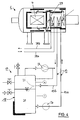
- a heat treatment furnace 1 is shown, which is designed as a vacuum furnace. Its interior is divided into a batch area 2 and a cooling area 3.
- a batch area 2 In the batch area 2 there is a batch 4, which consists of numerous workpieces and is surrounded by thermal insulation 5.
- This thermal insulation includes two movable flaps 6 and 7, which are used to control a cooling gas flow through the openings 8 and 9 in the sense of the flow arrows shown.
- the heating devices required for heating batch 4 are not shown for the sake of simplicity.
- the batch area 2 is separated from the cooling area 3 by a wall 10, which belongs to the thermal insulation 5.
- cooling area 3 there is a furnace heat exchanger 11 with cooling surfaces 12, which are shown only very schematically, and on the secondary side of which a liquid cooling medium is guided in a circuit 13, which includes the feed line 13a and the discharge line 13b.
- the heat exchanger 11 is surrounded by a further thermal insulation 14.
- a fan 15 with a drive motor 16 the quenching gas can be guided in a circuit in the sense of the flow arrows when the flaps 6 and 7 are open.
- the coolant circuit 13 includes a heat dissipation unit 17, which consists of a pressure-resistant and gas-tight storage tank 18, which is surrounded by heat insulation 19, of which only a part is shown symbolically.
- a storage volume 20 which can consist of one of the liquids described above, but in any case contains a substantial proportion of an evaporable liquid, in particular water.
- the storage volume comprises several 1000 liters of said liquid and has a constructive liquid level 21, above which there is a gas or vapor space 22.
- the storage tank 18 is connected via a line 23 to a vacuum pump 24 which, depending on the selected operating conditions, can consist of a mechanical vacuum pump, a pump set or simply a water jet pump. Any condensate formed can be returned to the storage tank through a line 25 indicated by dashed lines.
- the feed line 13a for the furnace heat exchanger 11 extends from the lower part of the storage tank 18 via a liquid pump 26, and the return line 13b opens into the vapor space 22, so that the liquid phase of the return can mix with the storage volume 20 immediately.
- Measuring devices 27 and 28 are used to measure pressure P and temperature T.
- the storage tank 18 also includes a water inlet 29, a gas inlet 30 and a safety valve 31 through which water vapor can escape at a pressure above approximately 1 bar.
- the operation of such a device can be described by way of example as follows:
- the storage tank 18 which has a volume of 8 m 3, there are 5 m 3 of water with a temperature of 20 ° C.
- the vacuum pump 14 which in this example is designed as a water jet pump
- the storage tank is evacuated to a pressure of 0.0123 bar, which corresponds to a boiling point of the water of 10 ° C.
- the temperature of the water gradually drops to 10 ° C, whereby 84.2 kg of water are evaporated.
- the storage tank 18 is then flooded to 0.042 bar with a gas such as air or nitrogen.
- a quenching process is then carried out in the heat treatment furnace 1, the cooling water heated in the heat exchanger 11 continuously being led through the storage tank 18 by the liquid pump 26 and cooled there accordingly.
- the water in the storage tank 18 is gradually heated, and would only start to boil at 30 ° C at the set pressure of 0.042 bar.
- heat amounts of about 3 megawatts are generated, which leads to a heating of the storage volume by 17.5 ° C to 27.5 ° C. This means that the water is kept below the boiling point.
- the heat dissipation unit 32 has a different structure than the heat dissipation aggreat 17 in FIG. 1: in the storage tank 18 there is a tank heat exchanger 33 below the constructive liquid level 21 for the storage volume 20, which tank heat exchanger 33 guides the cooling medium passed through the furnace heat exchanger 11 keeps separate from the storage volume 20.
- the lines 13a and 13b of the furnace heat exchanger 11 are connected to this tank heat exchanger 33.
- the evaporative cooling described causes large heat transfer coefficients, so that you can get by with a correspondingly small tank heat exchanger.
- a first condenser 34 is connected upstream of the vacuum pump 24 and a second condenser 35 is connected downstream.
- a second condenser 35 is connected downstream.
- the resulting condensates are returned to the storage tank 18 via the lines 34a and 35a.
- the time “t” is plotted dimensionless on the abscissa.
- the temperature T from 0 to 100 ° C. is plotted on the left ordinate and the pressure P up to about 1 bar on the right ordinate.
- the upper curve “P” stands for the pressure and the lower curve “T” stands for the temperature.
- the individual process stages are numbered continuously from 1 to 8.
- the storage tank 18 is filled with water at room temperature.
- the evacuation of the storage tank 18 takes place in connection with a temperature reduction to less than 10 ° C.
- the storage volume is kept at this temperature, but the pressure P is increased by flooding the storage tank 18 with a gas in accordance with the above information.
- the quenching process begins at constant pressure in the storage tank 18.
- the temperature T rises accordingly.
- the storage volume 20 begins to boil, so that the temperature T initially remains constant.
- the evacuation is continued by the vacuum pump 24.
- the deterrent has ended, and water is refilled so that the temperature drops again slightly as a result of the mixing process.
- section 7 there is a further evacuation (without supplying heat) and the storage volume 20 cools down to the initial state according to section 1.
- section 8 which corresponds to section 3, the storage tank 18 is again partially flooded to a slightly higher pressure. The operating cycle can now be repeated.
- the exemplary embodiment according to FIG. 4 differs from that according to FIG. 1 in that the furnace heat exchanger 37 contains two heat exchanger stages 38 and 39.
- the first heat exchanger stage 38 in the gas flow direction (see arrows shown) is connected via lines 38a and 38b to a normal water circuit, which can be, for example, a recooling system which works on the evaporation principle.
- the second heat exchanger stage 39 immediately following in the gas flow direction is connected in an analogous manner to the circuit 13, as shown in FIG. 1. This makes it possible to remove a large part of the short-term heat quantities via the first heat exchanger stage 38 in the usual way and to remove only the remaining amount of heat via the second heat exchanger stage 39 by evaporative cooling.
- the feed lines 13a and 13b open directly into the storage tank 18.
Landscapes
- Engineering & Computer Science (AREA)
- Chemical & Material Sciences (AREA)
- Mechanical Engineering (AREA)
- Physics & Mathematics (AREA)
- Thermal Sciences (AREA)
- Crystallography & Structural Chemistry (AREA)
- Materials Engineering (AREA)
- Metallurgy (AREA)
- Organic Chemistry (AREA)
- General Engineering & Computer Science (AREA)
Applications Claiming Priority (2)
| Application Number | Priority Date | Filing Date | Title |
|---|---|---|---|
| DE4435862A DE4435862C1 (de) | 1994-10-07 | 1994-10-07 | Verfahren und Vorrichtung zum Abkühlen, insbesondere zum Abschrecken, von Werkstücken durch Gase |
| DE4435862 | 1994-10-07 |
Publications (2)
| Publication Number | Publication Date |
|---|---|
| EP0705907A1 true EP0705907A1 (fr) | 1996-04-10 |
| EP0705907B1 EP0705907B1 (fr) | 1999-11-10 |
Family
ID=6530196
Family Applications (1)
| Application Number | Title | Priority Date | Filing Date |
|---|---|---|---|
| EP95114288A Expired - Lifetime EP0705907B1 (fr) | 1994-10-07 | 1995-09-12 | Procédé et installation pour le refroidissement au gaz de pièces à usiner |
Country Status (2)
| Country | Link |
|---|---|
| EP (1) | EP0705907B1 (fr) |
| DE (2) | DE4435862C1 (fr) |
Cited By (1)
| Publication number | Priority date | Publication date | Assignee | Title |
|---|---|---|---|---|
| CN108411083A (zh) * | 2018-04-04 | 2018-08-17 | 芜湖德海机器人科技有限公司 | 外热式真空热处理罐以及热处理方法 |
Families Citing this family (1)
| Publication number | Priority date | Publication date | Assignee | Title |
|---|---|---|---|---|
| DE19820083A1 (de) * | 1998-05-06 | 1999-11-11 | Ald Vacuum Techn Gmbh | Verfahren zum Abschrecken von Werkstücken und Wärmebehandlungsanlage zur Durchführung des Verfahrens |
Citations (3)
| Publication number | Priority date | Publication date | Assignee | Title |
|---|---|---|---|---|
| EP0415811A1 (fr) * | 1989-08-29 | 1991-03-06 | LE TRAITEMENT SOUS VIDE Société Anonyme dite: | Four de traitement thermique équipÀ© de moyens de refroidissement |
| US5121903A (en) * | 1991-03-11 | 1992-06-16 | Vacuum Furnace Systems Corporation | Quenching arrangement for a furnace |
| DE4422588C1 (de) * | 1994-06-28 | 1995-06-22 | Leybold Durferrit Gmbh | Verfahren zum Abschrecken von Werkstücken durch Gase und Wärmebehandlungsanlage zur Durchführung des Verfahrens |
-
1994
- 1994-10-07 DE DE4435862A patent/DE4435862C1/de not_active Expired - Fee Related
-
1995
- 1995-09-12 EP EP95114288A patent/EP0705907B1/fr not_active Expired - Lifetime
- 1995-09-12 DE DE59507217T patent/DE59507217D1/de not_active Expired - Lifetime
Patent Citations (3)
| Publication number | Priority date | Publication date | Assignee | Title |
|---|---|---|---|---|
| EP0415811A1 (fr) * | 1989-08-29 | 1991-03-06 | LE TRAITEMENT SOUS VIDE Société Anonyme dite: | Four de traitement thermique équipÀ© de moyens de refroidissement |
| US5121903A (en) * | 1991-03-11 | 1992-06-16 | Vacuum Furnace Systems Corporation | Quenching arrangement for a furnace |
| DE4422588C1 (de) * | 1994-06-28 | 1995-06-22 | Leybold Durferrit Gmbh | Verfahren zum Abschrecken von Werkstücken durch Gase und Wärmebehandlungsanlage zur Durchführung des Verfahrens |
Non-Patent Citations (1)
| Title |
|---|
| HTM HAERTEREI - TECHNISCHE MITTEILUNGEN, vol. 1, 1986, pages 20 - 21 |
Cited By (1)
| Publication number | Priority date | Publication date | Assignee | Title |
|---|---|---|---|---|
| CN108411083A (zh) * | 2018-04-04 | 2018-08-17 | 芜湖德海机器人科技有限公司 | 外热式真空热处理罐以及热处理方法 |
Also Published As
| Publication number | Publication date |
|---|---|
| DE4435862C1 (de) | 1995-08-24 |
| DE59507217D1 (de) | 1999-12-16 |
| EP0705907B1 (fr) | 1999-11-10 |
Similar Documents
| Publication | Publication Date | Title |
|---|---|---|
| EP2095370B1 (fr) | Installation technique nucléaire et procédé d'utilisation d'une installation technique nucléaire | |
| DE3809680C2 (fr) | ||
| EP0690138B1 (fr) | Procédé de trempe à gaz de pièces à usiner et installation de traitement thermique pour la mise en oeuvre de ce procédé | |
| EP2909452B1 (fr) | Appareil pour la production d'énergie électrique a l'aide d'un cycle organique de rankine | |
| DE102008013933A1 (de) | Verfahren und Vorrichtung zum Abtrennen eines Neutronenabsorbers von einem Kühlmittel eines Kühlkreislaufes | |
| EP0487002A2 (fr) | Dispositif de climatisation de l'habitacle d'un véhicule automobile | |
| DE4435862C1 (de) | Verfahren und Vorrichtung zum Abkühlen, insbesondere zum Abschrecken, von Werkstücken durch Gase | |
| EP1010954A1 (fr) | Procédé et dispositif de refroidissement d'un écoulement de gaz | |
| DE102016101292A1 (de) | Kühlvorrichtung für eine elektrische Antriebseinheit eines Fahrzeugs | |
| EP3568901A1 (fr) | Machine électrique tournante | |
| DE102015004802A1 (de) | Kühlvorrichtung | |
| EP2308576B1 (fr) | Evaporateur | |
| DE3004197A1 (de) | Verfahren zu rueckgewinnen von waermeenergie, die in den brueden von fuer thermische stofftrennprozesse eingesetzten mehrstufenverdampfern enthalten ist, und vorrichtung zur durchfuehrung des verfahrens | |
| DE19833739C1 (de) | Verfahren und Vorrichtung zum Abtrennen eines neutronenabsorbierenden Absorbers von einem Kühlmittel | |
| DE626864C (de) | Ausnutzung und Speicherung der Abwaerme einer kontinuierlichen Absorptionskaeltemaschine | |
| EP3580503B1 (fr) | Procédé de refroidissement d'un consommateur | |
| DE102012100645B4 (de) | ORC - Organischer Rankine Zyklus | |
| DE102010008408B4 (de) | Verfahren zum Betreiben eines Rückkühlkreislaufes mit einem Hybridkühler für eine Anlage mit einer diskontinuierlichen Wärmeabgabe und Vorrichtung hierfür | |
| DE2752005A1 (de) | Verfahren zum kuehlen von fluessigkeit in einem geschlossenen behaelter und vorrichtung zum ausfuehren des verfahrens | |
| DE19538348A1 (de) | Absorptionswärmetransformationsanlage mit Zusatzkomponenten zur Steigerung der Nutzleistung bzw. Erweiterung der Grenzen für die Antriebs-, Nutz- oder Kühltemperaturen | |
| DE10046058A1 (de) | Verfahren und Anordnung zum Rückgewinnen von Wärme | |
| DE10254049A1 (de) | Direktgekühlter Ozongenerator | |
| DEP0050398DA (de) | Kühleinrichtung für Elektrogeräte, insbesondere für Trockengleichrichter | |
| DE2206841A1 (de) | Flüssigkeitsbehälter | |
| EP1245795A2 (fr) | Procédé pour éviter les dépôts dans un système à vapeur |
Legal Events
| Date | Code | Title | Description |
|---|---|---|---|
| PUAI | Public reference made under article 153(3) epc to a published international application that has entered the european phase |
Free format text: ORIGINAL CODE: 0009012 |
|
| AK | Designated contracting states |
Kind code of ref document: A1 Designated state(s): DE FR GB IT |
|
| 17P | Request for examination filed |
Effective date: 19960819 |
|
| GRAG | Despatch of communication of intention to grant |
Free format text: ORIGINAL CODE: EPIDOS AGRA |
|
| GRAG | Despatch of communication of intention to grant |
Free format text: ORIGINAL CODE: EPIDOS AGRA |
|
| GRAH | Despatch of communication of intention to grant a patent |
Free format text: ORIGINAL CODE: EPIDOS IGRA |
|
| 17Q | First examination report despatched |
Effective date: 19990415 |
|
| GRAH | Despatch of communication of intention to grant a patent |
Free format text: ORIGINAL CODE: EPIDOS IGRA |
|
| GRAA | (expected) grant |
Free format text: ORIGINAL CODE: 0009210 |
|
| ITF | It: translation for a ep patent filed | ||
| AK | Designated contracting states |
Kind code of ref document: B1 Designated state(s): DE FR GB IT |
|
| GBT | Gb: translation of ep patent filed (gb section 77(6)(a)/1977) |
Effective date: 19991110 |
|
| REF | Corresponds to: |
Ref document number: 59507217 Country of ref document: DE Date of ref document: 19991216 |
|
| ET | Fr: translation filed | ||
| RAP2 | Party data changed (patent owner data changed or rights of a patent transferred) |
Owner name: ALD VACUUM TECHNOLOGIES AG |
|
| REG | Reference to a national code |
Ref country code: FR Ref legal event code: CJ |
|
| PLBE | No opposition filed within time limit |
Free format text: ORIGINAL CODE: 0009261 |
|
| STAA | Information on the status of an ep patent application or granted ep patent |
Free format text: STATUS: NO OPPOSITION FILED WITHIN TIME LIMIT |
|
| 26N | No opposition filed | ||
| REG | Reference to a national code |
Ref country code: GB Ref legal event code: IF02 |
|
| PGFP | Annual fee paid to national office [announced via postgrant information from national office to epo] |
Ref country code: GB Payment date: 20090922 Year of fee payment: 15 |
|
| PGFP | Annual fee paid to national office [announced via postgrant information from national office to epo] |
Ref country code: DE Payment date: 20090922 Year of fee payment: 15 |
|
| PGFP | Annual fee paid to national office [announced via postgrant information from national office to epo] |
Ref country code: IT Payment date: 20090923 Year of fee payment: 15 |
|
| GBPC | Gb: european patent ceased through non-payment of renewal fee |
Effective date: 20100912 |
|
| PG25 | Lapsed in a contracting state [announced via postgrant information from national office to epo] |
Ref country code: IT Free format text: LAPSE BECAUSE OF NON-PAYMENT OF DUE FEES Effective date: 20100912 |
|
| REG | Reference to a national code |
Ref country code: FR Ref legal event code: ST Effective date: 20110531 |
|
| REG | Reference to a national code |
Ref country code: DE Ref legal event code: R119 Ref document number: 59507217 Country of ref document: DE Effective date: 20110401 |
|
| PG25 | Lapsed in a contracting state [announced via postgrant information from national office to epo] |
Ref country code: FR Free format text: LAPSE BECAUSE OF NON-PAYMENT OF DUE FEES Effective date: 20100930 Ref country code: DE Free format text: LAPSE BECAUSE OF NON-PAYMENT OF DUE FEES Effective date: 20110401 |
|
| PG25 | Lapsed in a contracting state [announced via postgrant information from national office to epo] |
Ref country code: GB Free format text: LAPSE BECAUSE OF NON-PAYMENT OF DUE FEES Effective date: 20100912 |
|
| PGFP | Annual fee paid to national office [announced via postgrant information from national office to epo] |
Ref country code: FR Payment date: 20091001 Year of fee payment: 15 |