EP0705913A1 - Verfahren zur Herstellung eines Kunststoffformwerkzeugs - Google Patents
Verfahren zur Herstellung eines Kunststoffformwerkzeugs Download PDFInfo
- Publication number
- EP0705913A1 EP0705913A1 EP95113378A EP95113378A EP0705913A1 EP 0705913 A1 EP0705913 A1 EP 0705913A1 EP 95113378 A EP95113378 A EP 95113378A EP 95113378 A EP95113378 A EP 95113378A EP 0705913 A1 EP0705913 A1 EP 0705913A1
- Authority
- EP
- European Patent Office
- Prior art keywords
- mandrel
- plastic forming
- forming dies
- metal
- manufacturing plastic
- Prior art date
- Legal status (The legal status is an assumption and is not a legal conclusion. Google has not performed a legal analysis and makes no representation as to the accuracy of the status listed.)
- Withdrawn
Links
- 239000004033 plastic Substances 0.000 title claims description 40
- 238000004519 manufacturing process Methods 0.000 title claims description 28
- 238000000034 method Methods 0.000 title abstract description 8
- 229910052751 metal Inorganic materials 0.000 claims abstract description 72
- 239000002184 metal Substances 0.000 claims abstract description 72
- 230000008021 deposition Effects 0.000 claims abstract description 59
- 125000002915 carbonyl group Chemical group [*:2]C([*:1])=O 0.000 claims abstract description 42
- 229920006015 heat resistant resin Polymers 0.000 claims abstract description 28
- 229910045601 alloy Inorganic materials 0.000 claims abstract description 13
- 239000000956 alloy Substances 0.000 claims abstract description 11
- 239000011248 coating agent Substances 0.000 claims abstract description 5
- 238000000576 coating method Methods 0.000 claims abstract description 5
- 229910052759 nickel Inorganic materials 0.000 claims description 47
- 238000010438 heat treatment Methods 0.000 claims description 12
- 238000009423 ventilation Methods 0.000 claims description 9
- 229910052715 tantalum Inorganic materials 0.000 claims description 2
- 229910052721 tungsten Inorganic materials 0.000 claims description 2
- 238000000151 deposition Methods 0.000 abstract description 51
- 230000004048 modification Effects 0.000 abstract description 8
- 238000012986 modification Methods 0.000 abstract description 8
- 230000001788 irregular Effects 0.000 abstract description 5
- 238000001465 metallisation Methods 0.000 abstract description 5
- 238000000926 separation method Methods 0.000 abstract description 4
- PXHVJJICTQNCMI-UHFFFAOYSA-N Nickel Chemical compound [Ni] PXHVJJICTQNCMI-UHFFFAOYSA-N 0.000 description 66
- 238000004070 electrodeposition Methods 0.000 description 9
- 238000005323 electroforming Methods 0.000 description 9
- 229910000838 Al alloy Inorganic materials 0.000 description 7
- 238000003860 storage Methods 0.000 description 7
- 239000003822 epoxy resin Substances 0.000 description 6
- 229920000647 polyepoxide Polymers 0.000 description 6
- 238000010586 diagram Methods 0.000 description 5
- 239000012159 carrier gas Substances 0.000 description 4
- 238000009713 electroplating Methods 0.000 description 4
- 125000000524 functional group Chemical group 0.000 description 4
- 239000007789 gas Substances 0.000 description 4
- LNEPOXFFQSENCJ-UHFFFAOYSA-N haloperidol Chemical compound C1CC(O)(C=2C=CC(Cl)=CC=2)CCN1CCCC(=O)C1=CC=C(F)C=C1 LNEPOXFFQSENCJ-UHFFFAOYSA-N 0.000 description 4
- RYGMFSIKBFXOCR-UHFFFAOYSA-N Copper Chemical compound [Cu] RYGMFSIKBFXOCR-UHFFFAOYSA-N 0.000 description 3
- 229910052802 copper Inorganic materials 0.000 description 3
- 239000010949 copper Substances 0.000 description 3
- 239000007788 liquid Substances 0.000 description 3
- 230000015572 biosynthetic process Effects 0.000 description 2
- 238000007664 blowing Methods 0.000 description 2
- 229910002091 carbon monoxide Inorganic materials 0.000 description 2
- 238000005266 casting Methods 0.000 description 2
- 238000006243 chemical reaction Methods 0.000 description 2
- 239000012530 fluid Substances 0.000 description 2
- 239000000463 material Substances 0.000 description 2
- 229920005989 resin Polymers 0.000 description 2
- 239000011347 resin Substances 0.000 description 2
- 230000008016 vaporization Effects 0.000 description 2
- 238000010792 warming Methods 0.000 description 2
- BQCADISMDOOEFD-UHFFFAOYSA-N Silver Chemical compound [Ag] BQCADISMDOOEFD-UHFFFAOYSA-N 0.000 description 1
- 238000010276 construction Methods 0.000 description 1
- 238000000354 decomposition reaction Methods 0.000 description 1
- 230000000694 effects Effects 0.000 description 1
- 238000005187 foaming Methods 0.000 description 1
- 238000002347 injection Methods 0.000 description 1
- 239000007924 injection Substances 0.000 description 1
- 239000000696 magnetic material Substances 0.000 description 1
- 229910052709 silver Inorganic materials 0.000 description 1
- 239000004332 silver Substances 0.000 description 1
- 238000005507 spraying Methods 0.000 description 1
Images


Classifications
-
- C—CHEMISTRY; METALLURGY
- C23—COATING METALLIC MATERIAL; COATING MATERIAL WITH METALLIC MATERIAL; CHEMICAL SURFACE TREATMENT; DIFFUSION TREATMENT OF METALLIC MATERIAL; COATING BY VACUUM EVAPORATION, BY SPUTTERING, BY ION IMPLANTATION OR BY CHEMICAL VAPOUR DEPOSITION, IN GENERAL; INHIBITING CORROSION OF METALLIC MATERIAL OR INCRUSTATION IN GENERAL
- C23C—COATING METALLIC MATERIAL; COATING MATERIAL WITH METALLIC MATERIAL; SURFACE TREATMENT OF METALLIC MATERIAL BY DIFFUSION INTO THE SURFACE, BY CHEMICAL CONVERSION OR SUBSTITUTION; COATING BY VACUUM EVAPORATION, BY SPUTTERING, BY ION IMPLANTATION OR BY CHEMICAL VAPOUR DEPOSITION, IN GENERAL
- C23C16/00—Chemical coating by decomposition of gaseous compounds, without leaving reaction products of surface material in the coating, i.e. chemical vapour deposition [CVD] processes
- C23C16/06—Chemical coating by decomposition of gaseous compounds, without leaving reaction products of surface material in the coating, i.e. chemical vapour deposition [CVD] processes characterised by the deposition of metallic material
- C23C16/16—Chemical coating by decomposition of gaseous compounds, without leaving reaction products of surface material in the coating, i.e. chemical vapour deposition [CVD] processes characterised by the deposition of metallic material from metal carbonyl compounds
-
- C—CHEMISTRY; METALLURGY
- C23—COATING METALLIC MATERIAL; COATING MATERIAL WITH METALLIC MATERIAL; CHEMICAL SURFACE TREATMENT; DIFFUSION TREATMENT OF METALLIC MATERIAL; COATING BY VACUUM EVAPORATION, BY SPUTTERING, BY ION IMPLANTATION OR BY CHEMICAL VAPOUR DEPOSITION, IN GENERAL; INHIBITING CORROSION OF METALLIC MATERIAL OR INCRUSTATION IN GENERAL
- C23C—COATING METALLIC MATERIAL; COATING MATERIAL WITH METALLIC MATERIAL; SURFACE TREATMENT OF METALLIC MATERIAL BY DIFFUSION INTO THE SURFACE, BY CHEMICAL CONVERSION OR SUBSTITUTION; COATING BY VACUUM EVAPORATION, BY SPUTTERING, BY ION IMPLANTATION OR BY CHEMICAL VAPOUR DEPOSITION, IN GENERAL
- C23C16/00—Chemical coating by decomposition of gaseous compounds, without leaving reaction products of surface material in the coating, i.e. chemical vapour deposition [CVD] processes
- C23C16/01—Chemical coating by decomposition of gaseous compounds, without leaving reaction products of surface material in the coating, i.e. chemical vapour deposition [CVD] processes on temporary substrates, e.g. substrates subsequently removed by etching
Definitions
- This invention relates to a method of manufacturing plastic forming dies using a mandrel (master model).
- Past method of manufacturing plastic forming dies with complicated irregular shapes, which are used for plastic injection formation or foaming, used electroforming Namely, first of all a plastic mandrel is made with desired shape and the conductivity of a metallic layer made by an electroless deposition on the surface of the plastic mandrel. Then, a thick metal layer of copper, nickel, or silver formed on this conductive layer by electro deposition and, the metallic skin is peeled from the plastic mandrel through electroforming.
- an electro-deposition layer formed by electro-plating means that it took time for the electro-plating layer to grow. Because of this, a long time was needed to get a forming die with the desired thickness. For example, the formation speed of an electro-deposition layer of nickel from electro-plating is 0.001 inch per hour.
- This invention proposes a manufacturing method for plastic forming dies to resolve the above problems in plastic forming die manufacturing methods from electroforming, to complete the manufacture of plastic forming dies in a short time, and reduce the work for modifications to the plastic forming die after it is finished. It is also the purpose of this invention to propose a manufacturing method for plastic forming dies which can thicken a shell at a desired, specific place and in which the electro-deposition and back up metal will not peel.
- the mandrel surface is heated to the metal carbonyl's deposition temperature and by introducing vapor on the mandrel surface a metallic layer is formed.
- the metal's deposition rate from the metal carbonyl vapor is remarkably higher than the rate from electroforming. Compared to electroforming with the same metal thickness, this is 10 times faster and the productivity is remarkably higher.
- the metal's deposition from metal carbonyl vapor is done evenly regardless of whether the mandrel shape is irregular, so that few modification or adjustment is needed after metal deposition layer is completed. Furthermore, separation is easy when the surface of the mandrel comprised of alloy Al or Al is formed by a heat resistant resin layer, the metal layer deposited by this method is easily peeled burning off the heat resistant resin after the metal carbonyl's metallic layer is formed.
- Fig. 1 shows an outline diagram of the apparatus used in the examples.
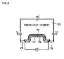
- Fig. 2 is a cross section view of the deposition chamber used by the mandrel in the example.
- Fig. 3 is a cross section view of the deposition chamber in the example of claim 11.
- Fig. 4 is a cross section view of the deposition chamber in the example of claim 12.
- a mandrel is affixed to a surface in a sealed deposition chamber and the surface of the mandrel is heated to the metal carbonyl's deposition temperature.
- the metallic layer forms on the surface of the mandrel by introducing metal carbonyl inside the deposition chamber.
- the metal carbonyl can use either a Ni, Co, Ta or W carbonyl.
- a heat resistant resin layer is formed on the mandrel surface comprising alloy Al or Al and heated oil in the heating method circulates in a pipe imbedded inside alloy Al or Al.
- a heating lamp can also be placed in back of alloy Al or Al in this heating method.
- a heat resistant layer is employed for the mandrel and heat can also be added with an electric wire imbedded in the heat resistant resin layer.
- a ventilation means is employed to supply metal carbonyl vapors directly at a specific part of the mandrel. Then, the mandrel is adhered to the surface in the sealed deposition chamber and the surface of the mandrel is heated to the metal carbonyl's deposition temperature. After a metal layer forms on the surface of the mandrel by introducing metal carbonyl inside the deposition chamber, a sprayed metal coating is made on the reverse side of the metal layer and the back up metal is cast on it directly.
- the mandrel surface is heated to the metal carbonyl's deposition temperature and the metal carbonyl vapor degrades the mandrel surface by introducing a metal carbonyl vapor on the mandrel surface where a metallic layer is formed.
- the metal's deposition rate from the metal carbonyl vapor is remarkably higher than the rate from electroforming.
- the Ni carbonyl deposition rate is 0.01 inches per hour so that compared to electro-forming this invention is 10 times faster and the productivity is remarkably higher.
- metal deposition from metal carbonyl vapor is done evenly regardless of whether the mandrel shape is irregular so there is no need to make additional modifications after the plastic forming die is complete.
- the mandrel material such materials that is resistant to heat at the metal carbonyl's deposition temperature and that can easily peel off from the deposited metal layer even if it is metal or it is resin.
- the mandrel material such materials that is resistant to heat at the metal carbonyl's deposition temperature and that can easily peel off from the deposited metal layer even if it is metal or it is resin.
- the surface of the mandrel comprising alloy Al or Al forms a heat resistant layer, and if the heat resistant resin layer is burnt off after the metal carbonyl's metallic layer is formed, then separation can be done easily.
- the Al or Al alloys which comprise the metal wick of the mandrel can be reused.
- Heat from the oil directly warming the back of the mandrel may be blown or the back of the mandrel may be illuminated by a warming lamp on alloy Al or Al which comprise the mandrel's metal wick.
- Warm oil circulates in a heating pipe imbedded inside alloy Al or Al and the surface of the mandrel is evenly heated so that a uniform metal layer forms.
- the mandrel is comprised of a heat resistant resin layer, then the same effect can be obtained by burying on electrical wire in the heat resistant resin layer.
- the desired thickness of a specific part of a metal layer's thickness can be formed from the metal carbonyl vapor supplied by a blowing means directly at a specific part of the mandrel. Also, after the metallic spray coating forms on the back of the metal layer. The sprayed metal coating is interposed as an internal chill back up metal so the back up metal and the deposition metal layer remain stuck and will not peel.
- Claims 3 through 5 of the present invention purport that the heat resistant temperature of the heat resistant resin layer is under 150 degrees Celsius. Even if an epoxy resin (a functional group of 2 epoxy resins) with a heat resistant temperature of under 150 degrees Celsius is substituted for an epoxy resin (a functional group of more than 3 epoxy resins) with a heat resistant temperature of 150 to 250 degrees Celsius for the heat resistant temperature layer, there is a metal wick for heating as a back up comprising the Al or Al alloys so even when the heat resistant resin layer heats to the heat decomposition temperature of nickel carbonyl (148-191 degrees Celsius), because of the complex combination metal wick used for heating there is no warping and after the metal deposition and peeling is very easy to do.
- the invention in Claim 11 for the blowing means in Claim 9 purports that a rotation motor be set outside the deposition chamber and a ventilation blade set inside the deposition chamber at a specific place which is rotated by the rotation motor.
- the invention in Claim 12 purports that the ventilation means is supplied with carbonyl vapor by a vapor branch pipe from a vapor supply pipe.
- Figure 1 shows a simple diagram of the processes in the example.
- Nickel powder is filled in and CO is supplied to reaction tower 10 and they react to obtain nickel carbonyl vapor.
- the nickel carbonyl vapor is introduced to condenser 12 and cooled to 38 degrees Celsius to make a nickel carbonyl liquid and then this fluid is sent to storage tank 14 for storage.
- the nickel carbonyl fluid is removed form storage tank 14 and set to vaporizing chamber 16.
- the nickel carbonyl vapor and carrier gas CO18 are sent to deposition chamber 20.
- Mandrel 22 is placed on the bottom center of deposition chamber 20 and an adiabatic plate 24 seals the space between the inner walls of mandrel 22 and deposition chamber 20.
- a vaporized temperature for nickel carbonyl of over 38 degrees Celsius is maintained inside deposition chamber 20 and the temperature in the deposition chamber is chilled up to the temperature at which nickel carbonyl vapor decomposes; 148 degrees Celsius.
- Mandrel 22 is constructed of an Al alloy metal wick 28 coated with heat resistant resin layer 26, and a heating pipe 32 provided inside metal wick 28 and oil warmed by heater 34 and circulated by pump 36 through heat pipe 32 and heat resistant resin layer 26 on the surface of mandrel 22 heated between 148 and 191 degrees Celsius, the temperature at which nickel carbonyl decomposes.
- Un-reacted nickel carbonyl is in the exhaust from deposition chamber 20 so the gas is removed after the nickel carbonyl is recovered from exhaust gas condenser 38. The recovered nickel carbonyl is returned to storage tank 14.
- Nickel powder is filled in and CO is supplied to reaction tower 10 and they react to obtain nickel carbonyl vapor. Then, the nickel carbonyl vapor is introduced to condenser 12 and cooled to 38 degrees Celsius to make a nickel carbonyl liquid which is sent to storage tank 14 for storage.
- Mandrel 22 is placed on the bottom center of deposition chamber 20 and an adiabatic plate 24 seals the space between the inner walls of mandrel 22 and deposition chamber 20.
- a vaporized temperature for nickel carbonyl of over 38 degrees Celsius is maintained inside deposition chamber 20 and the temperature in the deposition chamber is chilled until it is no higher than 148 degrees Celsius, the temperature at which nickel carbonyl decomposes.
- Mandrel 22 is comprised of an Al alloy metal wick 28 coated by a 10mm thick heat resistant resin layer, a 10mm copper heating pipe 32 provided inside this metal wick 28, oil warmed by heater 34 and circulated by pump 36 through heat pipe 32, and heat resistant resin layer 26 on the surface of mandrel 22 heated between 148 and 191 degrees Celsius, the temperature at which nickel carbonyl decomposes.
- Nickel layer 40 deposited on the surface of mandrel 22 is removed from deposition chamber 20 and heat resistant resin layer 26 is heated to a burning temperature, and nickel layer 40 can be easily peeled from mandrel 22 and, because the peeled nickel layer 40 was deposited evenly on the surface of mandrel 22, the plastic forming die can be used with almost no modifications. When the metal wick Al alloy is made with the same plastic die, the die can be reused.
- Diagram 2 shows mandrel 22 made by a heat, resistant resin layer which uses an electrical wire 42 imbedded inside the mandrel resulting from the heat resistant layer and, as in the above example, mandrel 22 is placed at the bottom center of deposition chamber 20 and the inner wall space between mandrel 22 and deposition chamber 20 is sealed with the adiabatic plate 24.
- the inside of deposition chamber 20 is maintained at a nickel carbonyl temperature of over 38 degrees Celsius and simultaneously the temperature of the inner walls of deposition chamber 20 are chilled so the temperature is not above 148 degrees Celsius, the temperature at which nickel carbonyl decomposes.
- Mandrel 22 with nickel layer 40 deposited on its surface is removed form deposition chamber 20 and as the heat is increased to a temperature, at which heat resistant resin layer 26 burns, nickel layer 40 can be easily peeled from mandrel 22 and, since peeled nickel layer 40 was deposited evenly on the surface of mandrel 22, the plastic forming die can be used with almost no modifications.
- Example 1 On the surface of the Al alloy metal wick 28 used in Example 1 is covered a functional group of 2 epoxy resins with a heat resistant temperature of 150 degrees Celsius to form a 10mm thick heat resistant resin layer 26.
- This mandrel 22 is placed at the bottom center of deposition chamber 20 and the space between the inner walls of mandrel 22 and deposition chamber 20 is sealed by the adiabatic plate 24.
- oil warmed by heater 34 is circulated by pump 36 through a 10mm copper pipe 32 set inside metal wick 28 and heat heat resistant resin layer 26 on the surface of mandrel 22 is heated to 148 - 191 degrees Celsius, the temperature at which nickel carbonyl decomposes but heat resistant resin layer 26 does not warp regardless of the increase in temperature.
- Example 1 a 4mm nickel layer 40 is deposited on the surface of mandrel 22.
- a 4mm nickel layer 40 is deposited on the surface of mandrel 22 by the same method shown in Example 1.
- Mandrel 22 on which surface nickel layer 40 is deposited in this or the reference example is removed from deposition chamber 20 and heated to a temperature at which heat resistant resin layer 26 burns and nickel layer 40 is peeled from mandrel 22.
- heat resistant resin layer 26 hardens at 300 degrees Celsius and a temperature above 300 degrees Celsius is necessary for complete separation.
- the benefit of this invention is that heat resistant resin layer 26 in this example can be easily separated at 300 degrees Celsius.
- Diagram 3 shows mandrel 22 with concave part 44 placed at the bottom center of deposition chamber 20 and ventilation blade 46 positioned on the axle so the air can blow toward concave part 44 of mandrel 22 and driven rotor 50 made of magnetic material fixed at the tip of axle 48.
- Rotation motor 52 is installed outside the wall of the deposition chamber separating it from driven rotor 50.
- Magnetic rotor 56 is installed on drive axle 54 of rotation motor 52 in the relative direction of the wall between it and driven rotor 50 and, when magnet rotor 56 rotates, driven rotor 50 rotates resulting in the rotation of rotation motor 52 and ventilation blade 46.
- the apparatus used in this example can circulate the carbonyl vapor to the difficult part to circulate, so concave part 44 of mandrel 22 can get a sufficient supply of carbonyl vapor and the thickness of the nickel layer at the concave part 44 can be controlled by controlling the number of the rotation motor's rotations.
- Diagram 4 shows mandrel 22 with two concave parts 44 placed at the bottom center of deposition chamber 20.
- Two vapor branch pipes 62 branch off from vapor supply branch 60 installed on the ceiling of the deposition chamber to supply carbonyl vapor and the tips of each vapor branch pipe are open and facing concave parts 44.
- vaporized nickel carbonyl is sent with carrier gas CO18 by vapor supply pipe 60 to deposition chamber 20 and nickel carbonyl vapors are supplied to concave parts 44 on mandrel 22 where it is difficult for nickel carbonyl vapors to circulate, by two vapor branch pipes 62 from vapor supply pipe 60. Because of this, it is difficult for the carbonyl vapors to circulate and the concave part 44 of mandrel 22 can get a sufficient supply of carbonyl vapor.
- the benefits of this invention for a manufacturing method for plastic forming dies as described above are the mandrel surface is heated to the metal carbonyl's deposition temperature and the metal carbonyl vapor degrades the mandrel surface by introducing a metal carbonyl vapor and a metallic layer is formed on the mandrel surface.
- the metal's deposition temperature from the metal carbonyl vapor is remarkably faster than temperatures from electro-casting. For example, it takes an Ni carbonyl one hour per 0.01 inches but compared to electro-casting Ni, this is 10 times faster and the productivity is remarkably higher. Also, metal deposition from metal carbonyl vapor is done evenly regardless of whether the mandrel shape is irregular so there is no need to make additional modifications after the plastic forming die is complete.
Landscapes
- Chemical & Material Sciences (AREA)
- General Chemical & Material Sciences (AREA)
- Chemical Kinetics & Catalysis (AREA)
- Engineering & Computer Science (AREA)
- Materials Engineering (AREA)
- Mechanical Engineering (AREA)
- Metallurgy (AREA)
- Organic Chemistry (AREA)
- Chemical Vapour Deposition (AREA)
- Moulds For Moulding Plastics Or The Like (AREA)
Applications Claiming Priority (4)
| Application Number | Priority Date | Filing Date | Title |
|---|---|---|---|
| JP20182794 | 1994-08-26 | ||
| JP201827/94 | 1994-08-26 | ||
| JP18581295A JPH0978239A (ja) | 1994-08-26 | 1995-07-21 | プラスチック成形型の製造方法 |
| JP185812/95 | 1995-07-21 |
Publications (1)
| Publication Number | Publication Date |
|---|---|
| EP0705913A1 true EP0705913A1 (de) | 1996-04-10 |
Family
ID=26503343
Family Applications (1)
| Application Number | Title | Priority Date | Filing Date |
|---|---|---|---|
| EP95113378A Withdrawn EP0705913A1 (de) | 1994-08-26 | 1995-08-25 | Verfahren zur Herstellung eines Kunststoffformwerkzeugs |
Country Status (4)
| Country | Link |
|---|---|
| EP (1) | EP0705913A1 (de) |
| JP (1) | JPH0978239A (de) |
| CN (1) | CN1130561A (de) |
| CA (1) | CA2156996A1 (de) |
Families Citing this family (4)
| Publication number | Priority date | Publication date | Assignee | Title |
|---|---|---|---|---|
| CA2437343A1 (en) * | 2003-08-08 | 2005-02-08 | Reinhart Weber | Hollow nickel shapes by vapour deposition |
| US20070218200A1 (en) * | 2006-03-16 | 2007-09-20 | Kenji Suzuki | Method and apparatus for reducing particle formation in a vapor distribution system |
| US20070234955A1 (en) * | 2006-03-29 | 2007-10-11 | Tokyo Electron Limited | Method and apparatus for reducing carbon monoxide poisoning at the peripheral edge of a substrate in a thin film deposition system |
| CN108010636A (zh) * | 2017-11-17 | 2018-05-08 | 金川集团股份有限公司 | 一种利用羰基法生产镍导电薄膜的方法 |
Citations (7)
| Publication number | Priority date | Publication date | Assignee | Title |
|---|---|---|---|---|
| DE1077941B (de) * | 1952-03-24 | 1960-03-17 | Ohio Commw Eng Co | Verfahren zum Herstellen einer Druckplatte durch Aufbringen eines Metallueberzuges auf eine Matrize |
| US2994297A (en) * | 1958-08-18 | 1961-08-01 | Union Carbide Corp | Apparatus for making molds by gas plating |
| US3175259A (en) * | 1961-10-05 | 1965-03-30 | Union Carbide Corp | Method of making pattern |
| US3196003A (en) * | 1963-01-14 | 1965-07-20 | Ohio Commw Eng Co | Process of making metal strips and sheets from waste metal |
| JPS60149780A (ja) * | 1984-01-13 | 1985-08-07 | Mitsui Eng & Shipbuild Co Ltd | Cvd被膜の形成方法 |
| EP0424183A1 (de) * | 1989-10-19 | 1991-04-24 | Inco Limited | Infrarot-Fenster |
| WO1994025638A1 (en) * | 1993-05-05 | 1994-11-10 | Weber Manufacturing Limited | Method and apparatus for producing nickel shell molds |
-
1995
- 1995-07-21 JP JP18581295A patent/JPH0978239A/ja active Pending
- 1995-08-25 CA CA 2156996 patent/CA2156996A1/en not_active Abandoned
- 1995-08-25 EP EP95113378A patent/EP0705913A1/de not_active Withdrawn
- 1995-08-26 CN CN 95116393 patent/CN1130561A/zh active Pending
Patent Citations (7)
| Publication number | Priority date | Publication date | Assignee | Title |
|---|---|---|---|---|
| DE1077941B (de) * | 1952-03-24 | 1960-03-17 | Ohio Commw Eng Co | Verfahren zum Herstellen einer Druckplatte durch Aufbringen eines Metallueberzuges auf eine Matrize |
| US2994297A (en) * | 1958-08-18 | 1961-08-01 | Union Carbide Corp | Apparatus for making molds by gas plating |
| US3175259A (en) * | 1961-10-05 | 1965-03-30 | Union Carbide Corp | Method of making pattern |
| US3196003A (en) * | 1963-01-14 | 1965-07-20 | Ohio Commw Eng Co | Process of making metal strips and sheets from waste metal |
| JPS60149780A (ja) * | 1984-01-13 | 1985-08-07 | Mitsui Eng & Shipbuild Co Ltd | Cvd被膜の形成方法 |
| EP0424183A1 (de) * | 1989-10-19 | 1991-04-24 | Inco Limited | Infrarot-Fenster |
| WO1994025638A1 (en) * | 1993-05-05 | 1994-11-10 | Weber Manufacturing Limited | Method and apparatus for producing nickel shell molds |
Non-Patent Citations (3)
| Title |
|---|
| MULLENDORE A W ET AL: "Wear resistance of ion-implanted, chemically vapor-deposited nickel die inserts", THIN SOLID FILMS, 1 MAY 1990, SWITZERLAND, vol. 186, no. 2, ISSN 0040-6090, pages 215 - 231, XP025843922, DOI: doi:10.1016/0040-6090(90)90144-3 * |
| PATENT ABSTRACTS OF JAPAN vol. 009, no. 317 (C - 319) 12 December 1985 (1985-12-12) * |
| T.W.BLACK ET AL: "TOOLMAKING WITHOUT MACHINING ... LONG-TERM RESEARCH PAYS OFF", THE TOOL ENGINEER, vol. 44, no. 6, pages 101 - 104 * |
Also Published As
| Publication number | Publication date |
|---|---|
| CN1130561A (zh) | 1996-09-11 |
| CA2156996A1 (en) | 1996-02-27 |
| JPH0978239A (ja) | 1997-03-25 |
Similar Documents
| Publication | Publication Date | Title |
|---|---|---|
| CA2045841C (en) | Method of producing nickel shell molds | |
| EP0727511B1 (de) | Verfahren zur Herstellung eines hohlen elektroformierten Produkts aus Edelmetall | |
| US5385760A (en) | Process for the production of a composite coating of a functional substance in a metal matrix on the surface of an article | |
| US4722770A (en) | Method for making continuous and closed hollow bodies, hollow bodies so obtained and apparatus for making the hollow spheres | |
| US4664758A (en) | Electroforming process | |
| EP0705913A1 (de) | Verfahren zur Herstellung eines Kunststoffformwerkzeugs | |
| US11542622B2 (en) | Electrodeposition from multiple electrolytes | |
| US5591485A (en) | Method and apparatus for producing nickel shell molds | |
| US20170253982A1 (en) | Additive-Based Process for Producing Micro-Channel Devices | |
| EP0166472B1 (de) | Verfahren zur Herstellung einer Kombination von Kunstharzelementen sowie eines mit solchen Elementen versehenen Trägers und eine Kombination von solchen Elementen | |
| Sole | Electroforming: methods, materials, and merchandise | |
| US6004447A (en) | Electroforming process | |
| US4949773A (en) | Production method of a mold for continuous casting | |
| MXPA95003671A (en) | Method for the manufacture of pieces to mold plasti | |
| JP2001020070A (ja) | 金属製品及びその製造方法 | |
| JPH11105039A (ja) | 射出成形用金型およびその製造方法 | |
| JPH01176513A (ja) | ポーラス金型 | |
| US8322397B2 (en) | Mold for injection molding and method of manufacturing thereof | |
| US382661A (en) | Dextee w | |
| JPH04220310A (ja) | 成形用金型の製造方法 | |
| JP2000000829A (ja) | プラスチック成形型用マンドレルおよびその製造方法 | |
| JP2010209389A (ja) | 温度調節管を有する電鋳殻の製造方法 | |
| JPH09300359A (ja) | 急加熱用金型及びその製造方法 | |
| KR20100138625A (ko) | 콜드 스프레이방법을 이용한 도금층의 형성방법 | |
| JPS5569285A (en) | Production of porous metal foil |
Legal Events
| Date | Code | Title | Description |
|---|---|---|---|
| PUAI | Public reference made under article 153(3) epc to a published international application that has entered the european phase |
Free format text: ORIGINAL CODE: 0009012 |
|
| AK | Designated contracting states |
Kind code of ref document: A1 Designated state(s): DE FR GB NL |
|
| 17P | Request for examination filed |
Effective date: 19961009 |
|
| 17Q | First examination report despatched |
Effective date: 19970915 |
|
| GRAG | Despatch of communication of intention to grant |
Free format text: ORIGINAL CODE: EPIDOS AGRA |
|
| STAA | Information on the status of an ep patent application or granted ep patent |
Free format text: STATUS: THE APPLICATION IS DEEMED TO BE WITHDRAWN |
|
| 18D | Application deemed to be withdrawn |
Effective date: 20010301 |