EP0705961A1 - Silencieux de gaz d'échappement - Google Patents
Silencieux de gaz d'échappement Download PDFInfo
- Publication number
- EP0705961A1 EP0705961A1 EP95111537A EP95111537A EP0705961A1 EP 0705961 A1 EP0705961 A1 EP 0705961A1 EP 95111537 A EP95111537 A EP 95111537A EP 95111537 A EP95111537 A EP 95111537A EP 0705961 A1 EP0705961 A1 EP 0705961A1
- Authority
- EP
- European Patent Office
- Prior art keywords
- chamber
- exhaust gas
- exhaust
- openings
- feed pipe
- Prior art date
- Legal status (The legal status is an assumption and is not a legal conclusion. Google has not performed a legal analysis and makes no representation as to the accuracy of the status listed.)
- Granted
Links
Images


Classifications
-
- F—MECHANICAL ENGINEERING; LIGHTING; HEATING; WEAPONS; BLASTING
- F01—MACHINES OR ENGINES IN GENERAL; ENGINE PLANTS IN GENERAL; STEAM ENGINES
- F01N—GAS-FLOW SILENCERS OR EXHAUST APPARATUS FOR MACHINES OR ENGINES IN GENERAL; GAS-FLOW SILENCERS OR EXHAUST APPARATUS FOR INTERNAL-COMBUSTION ENGINES
- F01N1/00—Silencing apparatus characterised by method of silencing
- F01N1/08—Silencing apparatus characterised by method of silencing by reducing exhaust energy by throttling or whirling
- F01N1/10—Silencing apparatus characterised by method of silencing by reducing exhaust energy by throttling or whirling in combination with sound-absorbing materials
-
- F—MECHANICAL ENGINEERING; LIGHTING; HEATING; WEAPONS; BLASTING
- F01—MACHINES OR ENGINES IN GENERAL; ENGINE PLANTS IN GENERAL; STEAM ENGINES
- F01N—GAS-FLOW SILENCERS OR EXHAUST APPARATUS FOR MACHINES OR ENGINES IN GENERAL; GAS-FLOW SILENCERS OR EXHAUST APPARATUS FOR INTERNAL-COMBUSTION ENGINES
- F01N1/00—Silencing apparatus characterised by method of silencing
- F01N1/08—Silencing apparatus characterised by method of silencing by reducing exhaust energy by throttling or whirling
-
- F—MECHANICAL ENGINEERING; LIGHTING; HEATING; WEAPONS; BLASTING
- F01—MACHINES OR ENGINES IN GENERAL; ENGINE PLANTS IN GENERAL; STEAM ENGINES
- F01N—GAS-FLOW SILENCERS OR EXHAUST APPARATUS FOR MACHINES OR ENGINES IN GENERAL; GAS-FLOW SILENCERS OR EXHAUST APPARATUS FOR INTERNAL-COMBUSTION ENGINES
- F01N1/00—Silencing apparatus characterised by method of silencing
- F01N1/08—Silencing apparatus characterised by method of silencing by reducing exhaust energy by throttling or whirling
- F01N1/089—Silencing apparatus characterised by method of silencing by reducing exhaust energy by throttling or whirling using two or more expansion chambers in series
-
- F—MECHANICAL ENGINEERING; LIGHTING; HEATING; WEAPONS; BLASTING
- F01—MACHINES OR ENGINES IN GENERAL; ENGINE PLANTS IN GENERAL; STEAM ENGINES
- F01N—GAS-FLOW SILENCERS OR EXHAUST APPARATUS FOR MACHINES OR ENGINES IN GENERAL; GAS-FLOW SILENCERS OR EXHAUST APPARATUS FOR INTERNAL-COMBUSTION ENGINES
- F01N2450/00—Methods or apparatus for fitting, inserting or repairing different elements
- F01N2450/20—Methods or apparatus for fitting, inserting or repairing different elements by mechanical joints, e.g. by deforming housing, tube, baffle plate or parts thereof
-
- F—MECHANICAL ENGINEERING; LIGHTING; HEATING; WEAPONS; BLASTING
- F01—MACHINES OR ENGINES IN GENERAL; ENGINE PLANTS IN GENERAL; STEAM ENGINES
- F01N—GAS-FLOW SILENCERS OR EXHAUST APPARATUS FOR MACHINES OR ENGINES IN GENERAL; GAS-FLOW SILENCERS OR EXHAUST APPARATUS FOR INTERNAL-COMBUSTION ENGINES
- F01N2470/00—Structure or shape of exhaust gas passages, pipes or tubes
- F01N2470/02—Tubes being perforated
-
- F—MECHANICAL ENGINEERING; LIGHTING; HEATING; WEAPONS; BLASTING
- F01—MACHINES OR ENGINES IN GENERAL; ENGINE PLANTS IN GENERAL; STEAM ENGINES
- F01N—GAS-FLOW SILENCERS OR EXHAUST APPARATUS FOR MACHINES OR ENGINES IN GENERAL; GAS-FLOW SILENCERS OR EXHAUST APPARATUS FOR INTERNAL-COMBUSTION ENGINES
- F01N2470/00—Structure or shape of exhaust gas passages, pipes or tubes
- F01N2470/18—Structure or shape of exhaust gas passages, pipes or tubes the axis of inlet or outlet tubes being other than the longitudinal axis of apparatus
-
- F—MECHANICAL ENGINEERING; LIGHTING; HEATING; WEAPONS; BLASTING
- F01—MACHINES OR ENGINES IN GENERAL; ENGINE PLANTS IN GENERAL; STEAM ENGINES
- F01N—GAS-FLOW SILENCERS OR EXHAUST APPARATUS FOR MACHINES OR ENGINES IN GENERAL; GAS-FLOW SILENCERS OR EXHAUST APPARATUS FOR INTERNAL-COMBUSTION ENGINES
- F01N2470/00—Structure or shape of exhaust gas passages, pipes or tubes
- F01N2470/24—Concentric tubes or tubes being concentric to housing, e.g. telescopically assembled
-
- F—MECHANICAL ENGINEERING; LIGHTING; HEATING; WEAPONS; BLASTING
- F01—MACHINES OR ENGINES IN GENERAL; ENGINE PLANTS IN GENERAL; STEAM ENGINES
- F01N—GAS-FLOW SILENCERS OR EXHAUST APPARATUS FOR MACHINES OR ENGINES IN GENERAL; GAS-FLOW SILENCERS OR EXHAUST APPARATUS FOR INTERNAL-COMBUSTION ENGINES
- F01N2490/00—Structure, disposition or shape of gas-chambers
- F01N2490/08—Two or more expansion chambers in series separated by apertured walls only
Definitions
- the invention relates to an exhaust silencer according to the preamble of patent claim 1.
- exhaust silencers for internal combustion engines are usually designed in several stages, i.e. the exhaust gas first flows through a reflection area and then through an absorption area. It mainly dampens low-frequency sound components in the reflection area, while mainly high-frequency sound components are damped in the absorption area.
- Such exhaust silencers do show a satisfactory result in terms of the damping that can be achieved, but they are disadvantageous since the individual areas are usually arranged one behind the other in the flow direction of the exhaust gas, since such a series arrangement results in a relatively large overall length, which is particularly compact a hood installation very difficult.
- an exhaust gas silencer for multi-cylinder internal combustion engines which has a resonator chamber, which - viewed in the flow direction of the exhaust gas - has a reflection chamber arranged downstream.
- the exhaust gas passes into the reflection chamber through a feed pipe protruding from one end face of the housing and from there through passage openings provided in its jacket into a third chamber surrounding the reflection chamber and filled with sound-absorbing material, in order to then step outside through a discharge pipe arranged coaxially with the feed pipe.
- the invention is therefore based on the object of providing a powerful exhaust gas silencer which, on the one hand, has a compact design and, on the other hand, can be produced efficiently and inexpensively.
- the solution according to the invention offers the advantage of a very compact design, which has a cross-sectional / length ratio which is distinguished from known exhaust silencers, the cross-section of which is substantially smaller than their overall length, in that the cross-section is larger than the overall length.
- the exhaust muffler according to the invention is therefore particularly suitable for under-hood installation in construction machines and tractors; it is also well suited for the increasingly widespread installation of side layers in the truck sector.
- the exhaust muffler according to the invention also offers advantages in terms of production insofar as it offers the possibility of a compact construction variable design of the interior structure and thus a simple assembly for different engine outputs and different installation situations.
- the first chamber surrounding the feed pipe which can be designed as a reflection chamber, primarily low-frequency sound components are damped, with the division of the main flow into individual flows additionally preventing an increase in the outflow pressure and achieved by relaxing eddy currents.
- the eccentric arrangement of the outer tube of the exhaust silencer to the first and second chambers which can be designed as an absorption chamber, there are different thicknesses for the insulating material, so that sound components are damped by it within a broad spectrum of the high-frequency range.
- the relatively large absorption surface ensures good overall damping, while at the same time good structure-borne noise and temperature insulation is created on the entire surface of the jacket, which means that an expensive sandwich construction with a double sheet jacket and additional insulation insert can be omitted.
- the multi-chamber system according to the invention shows, in comparison to known combination silencers, which usually have a small cross section and a comparatively large overall length, overall an optimal exhaust gas back pressure behavior with a relatively high degree of damping and a low structure-borne noise and heat radiation.
- the performance of the multi-chamber system can be increased if a further chamber with correspondingly arranged through openings for the exhaust gas is provided between the first and the second chamber.
- a particularly compact and powerful design results from the fact that the feed pipe and the first and the further chamber (s) are arranged coaxially to one another.
- the invention specified in claim 1 can be developed in accordance with the characterizing features of claims 5 and 6. Although the division of the main flow of the exhaust gas into two partial flows is impaired in the corresponding chambers, there are far larger discharge paths than the exhaust gas within each chamber, not by the shortest route to the passage openings of the next Chamber but flows essentially along the entire circumference of the inner or outer surface of the corresponding chambers.
- the formation of the two front absorption chambers on the one hand increases the damping in the high-frequency range, and on the other hand the exhaust silencer is provided with an insulation jacket on its entire surface, which further improves both structure-borne noise and temperature insulation.
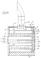
- the exhaust gas silencer shown in FIG. 1 has a feed pipe 1 for the exhaust gas to be connected to the engine-side exhaust pipe (not shown). This flows in the direction of the arrow into the feed pipe 1 which extends essentially over the entire length of the exhaust gas muffler and which is sealed gas-tight at its end opposite the exhaust gas inlet by a base 2.
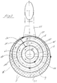
- the feed pipe 1 is provided with through openings 3 for the exhaust gas, which are arranged almost along its entire length in only one of its jacket halves, preferably — in relation to FIG. 2 — in its lower jacket half 4.
- the feed pipe 1 is arranged within a housing 5 of the exhaust silencer to be described in more detail, which is essentially formed by an outer pipe 6 and two end walls 7, 8, which are firmly connected to the pipe 6.
- the end walls 7, 8 are also firmly connected to the feed pipe 1.
- the feed pipe 1 is surrounded by a pipe 9, the two ends of which are also firmly connected to the walls 7, 8.
- the pipe 9 is arranged coaxially with the feed pipe 1, the space delimited by the two pipes 1, 9 forming a first chamber 11 for the exhaust gas.
- the pipe 9 Corresponding to the circular cross section of the feed pipe 1, the pipe 9 also has a circular cross section.
- the cross-sectional shape of these and also of the other tubes can be arbitrary, for example also oval.
- the tube 9 is of a substantially rectangular shape Cut made, the long sides of which are gas-tightly connected by folding. All tubes to be described later can be produced in the same way.
- the pipe 9, like the feed pipe 1, is provided on only one of its jacket halves - with reference to FIG. 2 - on its upper jacket half 12 with through openings 13 for the exhaust gas, which are arranged diametrically opposite the through openings 3 of the feed pipe 1.
- the exhaust-gas stream flowing out through the through-openings 3 and moving in the circumferential direction of the tubes becomes in Divide two sub-streams, the flow direction of one sub-stream being essentially clockwise and that of the other sub-stream essentially counter-clockwise (see dash-dot line in FIG. 2).
- the tube 9 is in turn surrounded by another tube 14 arranged coaxially with it, the front ends of which are also firmly connected to the walls 7, 8.
- the tube 14 is also provided with through-openings 15 for the exhaust gas, which are likewise arranged in only one of its jacket halves - in relation to FIG. 2 - in its lower jacket half 16.
- the through openings 15 of the tube 14 are thus diametrically opposite the through openings 13 of the tube 14.
- the space delimited by the tubes 9 and 14 forms a further chamber 17 for the exhaust gas, which, like the first chamber 11, serves as a reflection chamber.
- the exhaust gas flowing into the further chamber 17 via the passage openings 13 will leave the latter through the passage opening 15 of the pipe 14 and also has the widest possible flow path here, whereby the exhaust gas flow moving through the passage openings 13 also divides and the one partial flow will reach the passage opening 15 by a substantially clockwise direction and the other partial flow will reach this through a substantially counterclockwise flow (see also the dash-dot line of FIG. 2 ).
- the tube 14 is in turn surrounded by a perforated jacket 18, which is also firmly connected to the end walls 7, 8.
- the space delimited by the perforated jacket 18 and the tube 14 forms a second chamber 19 which is designed as an absorption chamber.
- the space formed in this way is filled with an insulating material 21, the wall thickness of which changes continuously over the entire circumference, as a result of which the absorption chamber 19 thus formed achieves a good damping effect within a broad spectrum of the high-frequency sound components.
- the perforated jacket 18 and the outer tube 6 have in their area diametrically opposite the through openings 15 an outlet opening 22 for the exhaust gas, so that the exhaust gas stream entering the chamber 19 through the through openings 15 also divide in the area of the through openings 15 and is in shape of two partial flows will also move pulsatingly to the outlet opening 22.
- This is connected to a discharge pipe 23, the longitudinal axis of which is directed transversely to the longitudinal axis of the feed pipe 1 and is arranged approximately in the middle of the total length of the housing 5, so that the so relaxed exhaust gas flows out in the direction of the arrow from the discharge pipe 23 of the exhaust silencer.
- FIG. 3 corresponds in its basic structure to the structure of the embodiment shown in FIG. In Figure 3, the same reference numerals are used as in Figures 1 and 2 for the matching parts.
- the difference between the two embodiments essentially consists in a somewhat different arrangement of the passage openings 3, 13 and 15 and the subdivision of the second chamber 19 and the further chamber 17.
- the passage openings 3 ′ of the feed pipe 1 are not arranged in its lower jacket half 4 but in its — in relation to FIG. 3 — left jacket half 4 ′. Accordingly, the passage openings 13 'of the tube 9 are not arranged in its upper jacket half 12, but in its right jacket half 12', based on FIG. 3.
- the through openings 15 'of the tube 14 are also not arranged in the lower jacket half 16 of the tube 14 as in the exemplary embodiment according to FIG. 2, rather the through openings 15' are arranged in the left jacket half 16 'of the tube 14 in relation to FIG. 3.
- a partition 25 is provided within the chamber 17 and a partition 26 within the chamber 19. Both partitions 25, 26 extend over the entire length of the housing 5.
- the arrangement is such that the exhaust gas stream leaving the feed pipe 1 through the passage openings 3 'divides as in the first embodiment, and the two partial flows flow through the chamber 11 in directions also opposite to one another in the circumferential direction of the pipe 9 and to the passage openings 13 'of the tube 14 move.
- the exhaust gas stream entering the chamber 17 through the through openings 13 ' will no longer be divided into two partial streams, but will flow through the chamber 17 in a clockwise direction, based on FIG. 3, and reach the through openings 15' of the pipe 14.
- a type of exhaust gas cushion will form between the partition wall 25 and the passage openings 13 'of the tube 9 immediately adjacent to it, which gradually flows through the chamber 17 clockwise through swirling of the exhaust gas components emerging from these passage openings and will reach the passage openings 15'.
- the exhaust gas Due to the arrangement of the partition 25 which blocks the shortest path for the exhaust gas between the passage openings 13 'and 15', the exhaust gas must flow through almost the entire circumference of the chamber 17, so that this results in the longest possible exhaust gas path and thus maximum relaxation of the exhaust gas .
- the flow conditions of the exhaust gas are similar when it passes through the through openings 15 ′ of the pipe 14 Partition 26 also blocks the shortest path to the outlet opening 22 of the discharge pipe 23, pulsate through the chamber 19 counterclockwise and thus reach the discharge pipe 23 on the longest possible flow path.
- a type of exhaust gas cushion will form on the side of the partition wall 26 adjacent to the through openings 15 ', which is also gradually integrated into the main flow of the exhaust gas by swirling the sound components emerging from the through openings 15' immediately adjacent to the partition wall 26 in order to lead to the outlet opening 22 of the discharge pipe 23 to arrive.
- This also results in the longest possible flow path for the exhaust gas within the chamber 19, which is almost three times the length of a flow path directed in the longitudinal direction of a chamber.
- the exhaust gas flow passing through it is expanded in a manner known per se, high-frequency sound components of the exhaust gas being damped within a broad spectrum by the different layer thickness of the material 21 arranged between the outer tube 6 and the perforated jacket 18.
- the end wall 7 is designed as an additional absorption chamber.
- the end wall 8 can also be designed as a further absorption chamber.
- FIG. 1 a there is between the wall 7 and the end of the feed pipe 1 that is remote from the exhaust gas inlet Insulating material 30 is arranged, which is supported against a perforated disc forming an intermediate wall 31.
- the intermediate wall 31 is connected to the gas-tightly closed end of the feed pipe 1 for reasons of stability and is provided on its circular surface with through openings 32 for the exhaust gas.
- the ends of the tubes 9 and 14 remote from the exhaust gas inlet are also firmly connected to the intermediate wall 31, the exhaust gas also flowing in and out of the chambers 11, 17 and 19 through the through openings 32 into the additional absorption chamber 33 formed in the longitudinal direction of the supply pipe this can flow back into these chambers and then into the outlet opening 22 of the discharge pipe 23.
- This on the one hand further increases the damping effect in the high-frequency range of the sound components and, in particular when the end wall 8 is designed in an analogous manner as a further absorption chamber, the entire surface of the exhaust silencer is thermally insulated, so that the entire insulating material 21, 30 is both sound-absorbing and also has a heat-insulating effect while at the same time minimizing the transmission of structure-borne noise.
Landscapes
- Engineering & Computer Science (AREA)
- Chemical & Material Sciences (AREA)
- Combustion & Propulsion (AREA)
- Mechanical Engineering (AREA)
- General Engineering & Computer Science (AREA)
- Exhaust Silencers (AREA)
Applications Claiming Priority (2)
| Application Number | Priority Date | Filing Date | Title |
|---|---|---|---|
| DE4435662A DE4435662A1 (de) | 1994-10-05 | 1994-10-05 | Abgasschalldämpfer |
| DE4435662 | 1994-10-05 |
Publications (2)
| Publication Number | Publication Date |
|---|---|
| EP0705961A1 true EP0705961A1 (fr) | 1996-04-10 |
| EP0705961B1 EP0705961B1 (fr) | 1999-05-06 |
Family
ID=6530061
Family Applications (1)
| Application Number | Title | Priority Date | Filing Date |
|---|---|---|---|
| EP95111537A Expired - Lifetime EP0705961B1 (fr) | 1994-10-05 | 1995-07-21 | Silencieux de gaz d'échappement |
Country Status (3)
| Country | Link |
|---|---|
| EP (1) | EP0705961B1 (fr) |
| AT (1) | ATE179777T1 (fr) |
| DE (2) | DE4435662A1 (fr) |
Cited By (1)
| Publication number | Priority date | Publication date | Assignee | Title |
|---|---|---|---|---|
| WO2016201489A1 (fr) * | 2015-06-17 | 2016-12-22 | Orbital Australia Pty | Silencieux |
Citations (6)
| Publication number | Priority date | Publication date | Assignee | Title |
|---|---|---|---|---|
| US1432797A (en) * | 1920-08-04 | 1922-10-24 | R E M Strickland | Muffler |
| GB276074A (en) * | 1926-05-18 | 1927-08-18 | Ole Solberg Bie | Improvements in exhaust-silencers |
| GB376815A (en) * | 1931-04-14 | 1932-07-14 | Frederick Heather | Improvements in and relating to silencers for gaseous currents |
| DE2257852A1 (de) | 1972-11-25 | 1974-05-30 | Eberspaecher J | Abgasschalldaempfer fuer mehrzylindrige brennkraftmaschinen |
| GB1364100A (en) * | 1971-11-03 | 1974-08-21 | Stemp L W | Gas silnencer |
| US4122913A (en) * | 1976-08-09 | 1978-10-31 | Stemp Leslie W | Silencer |
-
1994
- 1994-10-05 DE DE4435662A patent/DE4435662A1/de not_active Withdrawn
-
1995
- 1995-07-21 EP EP95111537A patent/EP0705961B1/fr not_active Expired - Lifetime
- 1995-07-21 DE DE59505829T patent/DE59505829D1/de not_active Expired - Fee Related
- 1995-07-21 AT AT95111537T patent/ATE179777T1/de not_active IP Right Cessation
Patent Citations (6)
| Publication number | Priority date | Publication date | Assignee | Title |
|---|---|---|---|---|
| US1432797A (en) * | 1920-08-04 | 1922-10-24 | R E M Strickland | Muffler |
| GB276074A (en) * | 1926-05-18 | 1927-08-18 | Ole Solberg Bie | Improvements in exhaust-silencers |
| GB376815A (en) * | 1931-04-14 | 1932-07-14 | Frederick Heather | Improvements in and relating to silencers for gaseous currents |
| GB1364100A (en) * | 1971-11-03 | 1974-08-21 | Stemp L W | Gas silnencer |
| DE2257852A1 (de) | 1972-11-25 | 1974-05-30 | Eberspaecher J | Abgasschalldaempfer fuer mehrzylindrige brennkraftmaschinen |
| US4122913A (en) * | 1976-08-09 | 1978-10-31 | Stemp Leslie W | Silencer |
Cited By (5)
| Publication number | Priority date | Publication date | Assignee | Title |
|---|---|---|---|---|
| WO2016201489A1 (fr) * | 2015-06-17 | 2016-12-22 | Orbital Australia Pty | Silencieux |
| CN107849955A (zh) * | 2015-06-17 | 2018-03-27 | 奥比托澳大利亚有限公司 | 消音器 |
| EP3311010A4 (fr) * | 2015-06-17 | 2018-12-05 | Orbital Australia PTY Ltd. | Silencieux |
| US10711670B2 (en) | 2015-06-17 | 2020-07-14 | Orbital Australia Pty Ltd | Muffler |
| CN107849955B (zh) * | 2015-06-17 | 2021-10-26 | 奥比托澳大利亚有限公司 | 消音器 |
Also Published As
| Publication number | Publication date |
|---|---|
| EP0705961B1 (fr) | 1999-05-06 |
| DE59505829D1 (de) | 1999-06-10 |
| DE4435662A1 (de) | 1996-04-11 |
| ATE179777T1 (de) | 1999-05-15 |
Similar Documents
| Publication | Publication Date | Title |
|---|---|---|
| DE69727502T2 (de) | Schalldämpfer mit trennwänden | |
| EP2543600B1 (fr) | Amortisseur de bruit pour un propulseur auxiliaire d'un avion | |
| EP0506686B1 (fr) | Conduite de gaz d'echappement avec un support de catalyseur recevant un ecoulement helicoidal | |
| DE2828006A1 (de) | Verfahren zur schalldaempfung von auspuffgasen eines verbrennungsmotors und schalldaempfer | |
| EP1959106B2 (fr) | Silencieux pour un système d'échappement | |
| EP1510667A2 (fr) | Silencieux | |
| DE19628798A1 (de) | Abgaskrümmer zur Abgasführung aus einer Brennkraftmaschine | |
| DE2908506C2 (de) | Schalldämpfer für Verbrennungskraftmaschinen | |
| DE2545364C3 (fr) | ||
| DE19743446C2 (de) | Abgasanlage für eine Brennkraftmaschine | |
| EP1051562B1 (fr) | Silencieux avec resonateur en derivation | |
| DE10300773A1 (de) | Abgasanlage für eine mehrzylindrige Brennkraftmaschine | |
| DE1292667B (de) | Schalldaempfer fuer stroemende Gase | |
| EP1321639B2 (fr) | Dispositif silencieux | |
| EP0455622B1 (fr) | Silencieux d'aspiration, plus particulièrement pour moteurs à combustion interne à deux temps | |
| EP1400662A1 (fr) | Silencieux à résonateur | |
| DE2816159C2 (de) | Reflexions-Schalldämpfer für Brennkraftmaschinen | |
| EP0705961B1 (fr) | Silencieux de gaz d'échappement | |
| EP1798390B1 (fr) | Système d'échappement pour moteurs à combustion interne | |
| DE1035973B (de) | Abgasschalldaempfungsanlage fuer Mehrzylinder-Brennkraftmaschinen | |
| DE2257852C2 (de) | Abgasschalldämpfer für mehrzylindrige Brennkraftmaschinen | |
| DE4021563A1 (de) | Abgasleitung fuer eine mindestens vierzylindrige brennkraftmaschine mit gerader zylinderanzahl | |
| WO2001023714A1 (fr) | Pot d'echappement | |
| DE3149632A1 (de) | Abgas-schalldaempfer fuer brennkraftmaschinen | |
| DE2318814A1 (de) | Schalldaempfvorrichtung |
Legal Events
| Date | Code | Title | Description |
|---|---|---|---|
| PUAI | Public reference made under article 153(3) epc to a published international application that has entered the european phase |
Free format text: ORIGINAL CODE: 0009012 |
|
| AK | Designated contracting states |
Kind code of ref document: A1 Designated state(s): AT DE FR IT |
|
| RBV | Designated contracting states (corrected) |
Designated state(s): AT DE FR IT |
|
| 17P | Request for examination filed |
Effective date: 19960808 |
|
| RAP1 | Party data changed (applicant data changed or rights of an application transferred) |
Owner name: ROTH-TECHNIK AUSTRIA GESELLSCHAFT M.B.H. |
|
| 17Q | First examination report despatched |
Effective date: 19980303 |
|
| GRAG | Despatch of communication of intention to grant |
Free format text: ORIGINAL CODE: EPIDOS AGRA |
|
| GRAG | Despatch of communication of intention to grant |
Free format text: ORIGINAL CODE: EPIDOS AGRA |
|
| GRAH | Despatch of communication of intention to grant a patent |
Free format text: ORIGINAL CODE: EPIDOS IGRA |
|
| GRAH | Despatch of communication of intention to grant a patent |
Free format text: ORIGINAL CODE: EPIDOS IGRA |
|
| GRAA | (expected) grant |
Free format text: ORIGINAL CODE: 0009210 |
|
| AK | Designated contracting states |
Kind code of ref document: B1 Designated state(s): AT DE FR IT |
|
| REF | Corresponds to: |
Ref document number: 179777 Country of ref document: AT Date of ref document: 19990515 Kind code of ref document: T |
|
| REF | Corresponds to: |
Ref document number: 59505829 Country of ref document: DE Date of ref document: 19990610 |
|
| ET | Fr: translation filed | ||
| PLBE | No opposition filed within time limit |
Free format text: ORIGINAL CODE: 0009261 |
|
| STAA | Information on the status of an ep patent application or granted ep patent |
Free format text: STATUS: NO OPPOSITION FILED WITHIN TIME LIMIT |
|
| 26N | No opposition filed | ||
| PGFP | Annual fee paid to national office [announced via postgrant information from national office to epo] |
Ref country code: FR Payment date: 20030721 Year of fee payment: 9 |
|
| PGFP | Annual fee paid to national office [announced via postgrant information from national office to epo] |
Ref country code: DE Payment date: 20040617 Year of fee payment: 10 |
|
| PGFP | Annual fee paid to national office [announced via postgrant information from national office to epo] |
Ref country code: AT Payment date: 20040722 Year of fee payment: 10 |
|
| PG25 | Lapsed in a contracting state [announced via postgrant information from national office to epo] |
Ref country code: FR Free format text: LAPSE BECAUSE OF NON-PAYMENT OF DUE FEES Effective date: 20050331 |
|
| REG | Reference to a national code |
Ref country code: FR Ref legal event code: ST |
|
| PG25 | Lapsed in a contracting state [announced via postgrant information from national office to epo] |
Ref country code: IT Free format text: LAPSE BECAUSE OF NON-PAYMENT OF DUE FEES Effective date: 20050721 Ref country code: AT Free format text: LAPSE BECAUSE OF NON-PAYMENT OF DUE FEES Effective date: 20050721 |
|
| PG25 | Lapsed in a contracting state [announced via postgrant information from national office to epo] |
Ref country code: DE Free format text: LAPSE BECAUSE OF NON-PAYMENT OF DUE FEES Effective date: 20060201 |