EP0705963A1 - Vorrichtung zur katalytischen Entgriffung von Abgasen von Brennkraftmaschinen - Google Patents
Vorrichtung zur katalytischen Entgriffung von Abgasen von Brennkraftmaschinen Download PDFInfo
- Publication number
- EP0705963A1 EP0705963A1 EP95114337A EP95114337A EP0705963A1 EP 0705963 A1 EP0705963 A1 EP 0705963A1 EP 95114337 A EP95114337 A EP 95114337A EP 95114337 A EP95114337 A EP 95114337A EP 0705963 A1 EP0705963 A1 EP 0705963A1
- Authority
- EP
- European Patent Office
- Prior art keywords
- foil
- per
- jacket
- combustion engines
- flat
- Prior art date
- Legal status (The legal status is an assumption and is not a legal conclusion. Google has not performed a legal analysis and makes no representation as to the accuracy of the status listed.)
- Withdrawn
Links
Images


Classifications
-
- F—MECHANICAL ENGINEERING; LIGHTING; HEATING; WEAPONS; BLASTING
- F01—MACHINES OR ENGINES IN GENERAL; ENGINE PLANTS IN GENERAL; STEAM ENGINES
- F01N—GAS-FLOW SILENCERS OR EXHAUST APPARATUS FOR MACHINES OR ENGINES IN GENERAL; GAS-FLOW SILENCERS OR EXHAUST APPARATUS FOR INTERNAL-COMBUSTION ENGINES
- F01N13/00—Exhaust or silencing apparatus characterised by constructional features
- F01N13/14—Exhaust or silencing apparatus characterised by constructional features having thermal insulation
-
- F—MECHANICAL ENGINEERING; LIGHTING; HEATING; WEAPONS; BLASTING
- F01—MACHINES OR ENGINES IN GENERAL; ENGINE PLANTS IN GENERAL; STEAM ENGINES
- F01N—GAS-FLOW SILENCERS OR EXHAUST APPARATUS FOR MACHINES OR ENGINES IN GENERAL; GAS-FLOW SILENCERS OR EXHAUST APPARATUS FOR INTERNAL-COMBUSTION ENGINES
- F01N3/00—Exhaust or silencing apparatus having means for purifying, rendering innocuous, or otherwise treating exhaust
- F01N3/08—Exhaust or silencing apparatus having means for purifying, rendering innocuous, or otherwise treating exhaust for rendering innocuous
- F01N3/10—Exhaust or silencing apparatus having means for purifying, rendering innocuous, or otherwise treating exhaust for rendering innocuous by thermal or catalytic conversion of noxious components of exhaust
- F01N3/18—Exhaust or silencing apparatus having means for purifying, rendering innocuous, or otherwise treating exhaust for rendering innocuous by thermal or catalytic conversion of noxious components of exhaust characterised by methods of operation; Control
- F01N3/20—Exhaust or silencing apparatus having means for purifying, rendering innocuous, or otherwise treating exhaust for rendering innocuous by thermal or catalytic conversion of noxious components of exhaust characterised by methods of operation; Control specially adapted for catalytic conversion
- F01N3/2006—Periodically heating or cooling catalytic reactors, e.g. at cold starting or overheating
- F01N3/2013—Periodically heating or cooling catalytic reactors, e.g. at cold starting or overheating using electric or magnetic heating means
-
- F—MECHANICAL ENGINEERING; LIGHTING; HEATING; WEAPONS; BLASTING
- F01—MACHINES OR ENGINES IN GENERAL; ENGINE PLANTS IN GENERAL; STEAM ENGINES
- F01N—GAS-FLOW SILENCERS OR EXHAUST APPARATUS FOR MACHINES OR ENGINES IN GENERAL; GAS-FLOW SILENCERS OR EXHAUST APPARATUS FOR INTERNAL-COMBUSTION ENGINES
- F01N3/00—Exhaust or silencing apparatus having means for purifying, rendering innocuous, or otherwise treating exhaust
- F01N3/08—Exhaust or silencing apparatus having means for purifying, rendering innocuous, or otherwise treating exhaust for rendering innocuous
- F01N3/10—Exhaust or silencing apparatus having means for purifying, rendering innocuous, or otherwise treating exhaust for rendering innocuous by thermal or catalytic conversion of noxious components of exhaust
- F01N3/24—Exhaust or silencing apparatus having means for purifying, rendering innocuous, or otherwise treating exhaust for rendering innocuous by thermal or catalytic conversion of noxious components of exhaust characterised by constructional aspects of converting apparatus
- F01N3/28—Construction of catalytic reactors
- F01N3/2803—Construction of catalytic reactors characterised by structure, by material or by manufacturing of catalyst support
- F01N3/2807—Metal other than sintered metal
- F01N3/281—Metallic honeycomb monoliths made of stacked or rolled sheets, foils or plates
-
- F—MECHANICAL ENGINEERING; LIGHTING; HEATING; WEAPONS; BLASTING
- F01—MACHINES OR ENGINES IN GENERAL; ENGINE PLANTS IN GENERAL; STEAM ENGINES
- F01N—GAS-FLOW SILENCERS OR EXHAUST APPARATUS FOR MACHINES OR ENGINES IN GENERAL; GAS-FLOW SILENCERS OR EXHAUST APPARATUS FOR INTERNAL-COMBUSTION ENGINES
- F01N3/00—Exhaust or silencing apparatus having means for purifying, rendering innocuous, or otherwise treating exhaust
- F01N3/08—Exhaust or silencing apparatus having means for purifying, rendering innocuous, or otherwise treating exhaust for rendering innocuous
- F01N3/10—Exhaust or silencing apparatus having means for purifying, rendering innocuous, or otherwise treating exhaust for rendering innocuous by thermal or catalytic conversion of noxious components of exhaust
- F01N3/24—Exhaust or silencing apparatus having means for purifying, rendering innocuous, or otherwise treating exhaust for rendering innocuous by thermal or catalytic conversion of noxious components of exhaust characterised by constructional aspects of converting apparatus
- F01N3/28—Construction of catalytic reactors
- F01N3/2839—Arrangements for mounting catalyst support in housing, e.g. with means for compensating thermal expansion or vibration
- F01N3/2853—Arrangements for mounting catalyst support in housing, e.g. with means for compensating thermal expansion or vibration using mats or gaskets between catalyst body and housing
-
- F—MECHANICAL ENGINEERING; LIGHTING; HEATING; WEAPONS; BLASTING
- F01—MACHINES OR ENGINES IN GENERAL; ENGINE PLANTS IN GENERAL; STEAM ENGINES
- F01N—GAS-FLOW SILENCERS OR EXHAUST APPARATUS FOR MACHINES OR ENGINES IN GENERAL; GAS-FLOW SILENCERS OR EXHAUST APPARATUS FOR INTERNAL-COMBUSTION ENGINES
- F01N3/00—Exhaust or silencing apparatus having means for purifying, rendering innocuous, or otherwise treating exhaust
- F01N3/08—Exhaust or silencing apparatus having means for purifying, rendering innocuous, or otherwise treating exhaust for rendering innocuous
- F01N3/10—Exhaust or silencing apparatus having means for purifying, rendering innocuous, or otherwise treating exhaust for rendering innocuous by thermal or catalytic conversion of noxious components of exhaust
- F01N3/24—Exhaust or silencing apparatus having means for purifying, rendering innocuous, or otherwise treating exhaust for rendering innocuous by thermal or catalytic conversion of noxious components of exhaust characterised by constructional aspects of converting apparatus
- F01N3/28—Construction of catalytic reactors
- F01N3/2839—Arrangements for mounting catalyst support in housing, e.g. with means for compensating thermal expansion or vibration
- F01N3/2853—Arrangements for mounting catalyst support in housing, e.g. with means for compensating thermal expansion or vibration using mats or gaskets between catalyst body and housing
- F01N3/2864—Arrangements for mounting catalyst support in housing, e.g. with means for compensating thermal expansion or vibration using mats or gaskets between catalyst body and housing the mats or gaskets comprising two or more insulation layers
-
- F—MECHANICAL ENGINEERING; LIGHTING; HEATING; WEAPONS; BLASTING
- F01—MACHINES OR ENGINES IN GENERAL; ENGINE PLANTS IN GENERAL; STEAM ENGINES
- F01N—GAS-FLOW SILENCERS OR EXHAUST APPARATUS FOR MACHINES OR ENGINES IN GENERAL; GAS-FLOW SILENCERS OR EXHAUST APPARATUS FOR INTERNAL-COMBUSTION ENGINES
- F01N3/00—Exhaust or silencing apparatus having means for purifying, rendering innocuous, or otherwise treating exhaust
- F01N3/08—Exhaust or silencing apparatus having means for purifying, rendering innocuous, or otherwise treating exhaust for rendering innocuous
- F01N3/10—Exhaust or silencing apparatus having means for purifying, rendering innocuous, or otherwise treating exhaust for rendering innocuous by thermal or catalytic conversion of noxious components of exhaust
- F01N3/24—Exhaust or silencing apparatus having means for purifying, rendering innocuous, or otherwise treating exhaust for rendering innocuous by thermal or catalytic conversion of noxious components of exhaust characterised by constructional aspects of converting apparatus
- F01N3/28—Construction of catalytic reactors
- F01N3/2882—Catalytic reactors combined or associated with other devices, e.g. exhaust silencers or other exhaust purification devices
-
- F—MECHANICAL ENGINEERING; LIGHTING; HEATING; WEAPONS; BLASTING
- F01—MACHINES OR ENGINES IN GENERAL; ENGINE PLANTS IN GENERAL; STEAM ENGINES
- F01N—GAS-FLOW SILENCERS OR EXHAUST APPARATUS FOR MACHINES OR ENGINES IN GENERAL; GAS-FLOW SILENCERS OR EXHAUST APPARATUS FOR INTERNAL-COMBUSTION ENGINES
- F01N2250/00—Combinations of different methods of purification
-
- Y—GENERAL TAGGING OF NEW TECHNOLOGICAL DEVELOPMENTS; GENERAL TAGGING OF CROSS-SECTIONAL TECHNOLOGIES SPANNING OVER SEVERAL SECTIONS OF THE IPC; TECHNICAL SUBJECTS COVERED BY FORMER USPC CROSS-REFERENCE ART COLLECTIONS [XRACs] AND DIGESTS
- Y02—TECHNOLOGIES OR APPLICATIONS FOR MITIGATION OR ADAPTATION AGAINST CLIMATE CHANGE
- Y02T—CLIMATE CHANGE MITIGATION TECHNOLOGIES RELATED TO TRANSPORTATION
- Y02T10/00—Road transport of goods or passengers
- Y02T10/10—Internal combustion engine [ICE] based vehicles
- Y02T10/12—Improving ICE efficiencies
Definitions
- the subject of this invention is an apparatus for catalytic purification of gases from combustion engines, particularly those with spark ignition.
- Drawback of this apparatus is its oval shape and the method of production thereof. In the course of the rolling process catalytic coating cracks over the fold peaks, thus damaging the insert.
- Polish Patent Application No. 298906 apparatus for purification of gases from combustion engines consisting of a box-like metal casing with two openings: inlet and outlet one, accommodating shapes mode from flat sheets and folded sheets covered with a transition layer and catalyst, lying alternately one on another. Said shapes have identical dimensions and have the form of a rectangle.
- the nature of the apparatus according to the invention consists in that the package consisting of alternately and transversally laid flat foil and longitudinally folded foil coated with a catalytic layer has the shape of a bellows and is accommodated in a bi-partite jacket consisting of two halves by means of a grip.
- the flat foil over its entire length has uniformly spaced cuts.
- the longitudinally folded foil has folds arranged in such a way that the distance between the fold peaks increases from the longitudinal axis toward the foil edge.
- Said longitudinally folded foil is perforated and has cuts uniformly distributed over its entire length.
- At the inlet of the combustion gases to the bi-partite jacket there is a magnetizer consisting of two rings which are closed in a housing. Said jacket is insulated with a thermo-insulating layer.
- both catalytic layers consist from two foils which are appropriately folded in such a way that they form a rigid package and do not require soldering.
- the folding method does not damage the catalytic layer and does not lead to cracking of the material. Because of the foil folding method being used the catalytic layer can be applied after the production of folds.
- Magnetizer situated at the inlet of the combustion gases improves the efficiency of the apparatus, whereas the insulating layer prevents emission of heat into the environment of the apparatus.
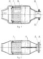
- Fig. 1 presents the apparatus in half-view half-section looked upon from above.
- Fig. 2 illustrates the apparatus shown in half- view half-section looked upon from the side.
- Fig. 3 shows the apparatus in -view half-section when looked upon from the side of the inlet of combustion gases,
- Fig. 4 visualizes a flat foil.
- Fig. 5 presents a longitudinally folded foil.
- Fig. 6 shows a fragment of a package,
- Fig. 7 presents the arrangement of folds in the longitudinally folded foil
- Package 1 consists of a flat foil 2 and longitudinally folded foil 3. Both foils 2 and 3 coated with a catalytic layer are alternately and transversally laid in a bellows-like manner.
- the longitudinally folded foil has folds arranged in such a way that the distance between the fold peaks increases from longitudinal axis ⁇ toward the edge of the foil 3.
- the longitudinally folded foil 3 has perforations 6 and cuts-ins 7, uniformly distributed over its entire length. On the flat foil there are also cuts 5 uniformly distributed over its length.
- a magnetizer 9 consisting of two rings 10. accommodated in a closed housing. Between the package 1 and the grip 12 there is thermo- insulating layer 13.
- Apparatus is produced in such a way that cuts 5 uniformly distributed over the entire length of the said foil are made on the flat foil 2 coated with a catalytic layer.
- Prior to folding the foil 3 cuts uniformly spaced over its length are being made and perforations are being made at the ends of the foil 3.
- the foil 3 is being rolled and passes first through one pair of roll mills, where one fold is made, and next through the subsequent ten pairs of milling rolls in such a way that after passing through each pair of rolls a pair of folds is added.
- Both the flat foil 2, as well as the longitudinally folded foil 3 is being folded at the cuts 5 and 7.
- both foils 2 and 3 are being alternately and transversally laid one on another so that they obtain a bellows-like shape.
- the compact package 1 is being fixed in grips 12 and then in two-partite jacket 4 with a previously placed thermo-insulating layer 13. Finally, both halves of the jacket 4 are being soldered and at the inlet 8 of the combustion gases to the jacket 4 there is mounted magnetizer 9.
Landscapes
- Chemical & Material Sciences (AREA)
- Engineering & Computer Science (AREA)
- Chemical Kinetics & Catalysis (AREA)
- Combustion & Propulsion (AREA)
- Mechanical Engineering (AREA)
- General Engineering & Computer Science (AREA)
- Health & Medical Sciences (AREA)
- Toxicology (AREA)
- Exhaust Gas After Treatment (AREA)
- Catalysts (AREA)
Applications Claiming Priority (2)
| Application Number | Priority Date | Filing Date | Title |
|---|---|---|---|
| PL94305034A PL174466B1 (pl) | 1994-09-12 | 1994-09-12 | Urządzenie do katalitycznego oczyszczania gazów z silników spalinowych oraz sposób wytwarzania urządzenia do katalitycznego oczyszczania gazów z silników spalinowych |
| PL30503494 | 1994-09-12 |
Publications (1)
| Publication Number | Publication Date |
|---|---|
| EP0705963A1 true EP0705963A1 (de) | 1996-04-10 |
Family
ID=20063225
Family Applications (1)
| Application Number | Title | Priority Date | Filing Date |
|---|---|---|---|
| EP95114337A Withdrawn EP0705963A1 (de) | 1994-09-12 | 1995-09-12 | Vorrichtung zur katalytischen Entgriffung von Abgasen von Brennkraftmaschinen |
Country Status (3)
| Country | Link |
|---|---|
| EP (1) | EP0705963A1 (de) |
| CZ (1) | CZ234995A3 (de) |
| PL (1) | PL174466B1 (de) |
Cited By (1)
| Publication number | Priority date | Publication date | Assignee | Title |
|---|---|---|---|---|
| EP1136669A2 (de) | 2000-03-21 | 2001-09-26 | Kemira Metalkat Oy | Katalysatorträger |
Citations (7)
| Publication number | Priority date | Publication date | Assignee | Title |
|---|---|---|---|---|
| EP0117602A2 (de) * | 1983-02-28 | 1984-09-05 | General Motors Corporation | Katalysatorträger |
| EP0151229A1 (de) * | 1983-11-19 | 1985-08-14 | Süddeutsche Kühlerfabrik Julius Fr. Behr GmbH & Co. KG | Matrix für einen katalytischen Reaktor |
| EP0316596A2 (de) * | 1987-11-13 | 1989-05-24 | Emitec Gesellschaft für Emissionstechnologie mbH | Verfahren und Vorrichtung zur Herstellung eines Trägerkörpers für einen katalytischen Reaktor |
| DE8908738U1 (de) * | 1989-07-18 | 1989-09-07 | Emitec Gesellschaft für Emissionstechnologie mbH, 5204 Lohmar | Wabenkörper mit internen Strömungsleitflächen, insbesondere Katalysatorkörper für Kraftfahrzeuge |
| WO1992002717A1 (de) * | 1990-08-10 | 1992-02-20 | Emitec Gesellschaft Für Emissionstechnologie Mbh | Wabenkörper mit querschnittsbereichen unterschiedlicher kanalgrössen, insbesondere katalysator-trägerkörper |
| JPH05171918A (ja) * | 1991-12-25 | 1993-07-09 | Hitachi Ltd | 未燃物を含む排ガスの浄化装置 |
| PL101000U1 (en) | 1994-08-04 | 1996-02-05 | Huta Baildon | Apapratus for purifying internal combustion engine exhaust gases |
-
1994
- 1994-09-12 PL PL94305034A patent/PL174466B1/pl unknown
-
1995
- 1995-09-12 EP EP95114337A patent/EP0705963A1/de not_active Withdrawn
- 1995-09-12 CZ CZ952349A patent/CZ234995A3/cs unknown
Patent Citations (7)
| Publication number | Priority date | Publication date | Assignee | Title |
|---|---|---|---|---|
| EP0117602A2 (de) * | 1983-02-28 | 1984-09-05 | General Motors Corporation | Katalysatorträger |
| EP0151229A1 (de) * | 1983-11-19 | 1985-08-14 | Süddeutsche Kühlerfabrik Julius Fr. Behr GmbH & Co. KG | Matrix für einen katalytischen Reaktor |
| EP0316596A2 (de) * | 1987-11-13 | 1989-05-24 | Emitec Gesellschaft für Emissionstechnologie mbH | Verfahren und Vorrichtung zur Herstellung eines Trägerkörpers für einen katalytischen Reaktor |
| DE8908738U1 (de) * | 1989-07-18 | 1989-09-07 | Emitec Gesellschaft für Emissionstechnologie mbH, 5204 Lohmar | Wabenkörper mit internen Strömungsleitflächen, insbesondere Katalysatorkörper für Kraftfahrzeuge |
| WO1992002717A1 (de) * | 1990-08-10 | 1992-02-20 | Emitec Gesellschaft Für Emissionstechnologie Mbh | Wabenkörper mit querschnittsbereichen unterschiedlicher kanalgrössen, insbesondere katalysator-trägerkörper |
| JPH05171918A (ja) * | 1991-12-25 | 1993-07-09 | Hitachi Ltd | 未燃物を含む排ガスの浄化装置 |
| PL101000U1 (en) | 1994-08-04 | 1996-02-05 | Huta Baildon | Apapratus for purifying internal combustion engine exhaust gases |
Non-Patent Citations (1)
| Title |
|---|
| PATENT ABSTRACTS OF JAPAN vol. 17, no. 584 (M - 1501) 25 October 1993 (1993-10-25) * |
Cited By (1)
| Publication number | Priority date | Publication date | Assignee | Title |
|---|---|---|---|---|
| EP1136669A2 (de) | 2000-03-21 | 2001-09-26 | Kemira Metalkat Oy | Katalysatorträger |
Also Published As
| Publication number | Publication date |
|---|---|
| PL305034A1 (en) | 1996-03-18 |
| PL174466B1 (pl) | 1998-07-31 |
| CZ234995A3 (en) | 1996-03-13 |
Similar Documents
| Publication | Publication Date | Title |
|---|---|---|
| US5094074A (en) | Catalytic converter with metallic carrier and method for producing same | |
| EP0837229B1 (de) | Verfahren zur Herstellung eines Katalysators einer Brennkraftmaschine | |
| US5170624A (en) | Composite catalytic converter | |
| US4559205A (en) | Catalytic converter substrate and retainer assembly | |
| KR940007735B1 (ko) | 금속박판을 압연 또는 라미네이션하여 만든 이중 또는 다중물결무늬 또는 파형구조를 가지는 금속촉매운반체몸체 또는 지지몸체 | |
| JPH0626331A (ja) | 複合接触転化器 | |
| JPH04284852A (ja) | 触媒コンバーター用触媒コア | |
| US7252809B2 (en) | Radial-flow and segmented honeycomb body | |
| EP0512659A2 (de) | Band aus gewellter, dünner Metallfolie | |
| JPH01130736A (ja) | 触媒反応容器用支持体の形成方法及び装置 | |
| US8661673B2 (en) | Method of installing a multi-layer batt, blanket or mat in an exhaust gas aftertreatment or acoustic device | |
| US8505203B2 (en) | Method of installing a longitudinally offset multi-layer mat in an exhaust gas aftertreatment or acoustic device | |
| US5852274A (en) | Electrically heatable catalytic converter | |
| RU2006102207A (ru) | Металлическая сотовая структура и способ ее изготовления | |
| RU2149084C1 (ru) | Элемент с сотовой структурой, соединенный с трубчатым кожухом только на отдельных участках | |
| JPS63137756A (ja) | 金属製触媒担体とその製法 | |
| US5133944A (en) | Method and device for the catalytic cleaning of exhaust gases of internal combustion engines | |
| PL174466B1 (pl) | Urządzenie do katalitycznego oczyszczania gazów z silników spalinowych oraz sposób wytwarzania urządzenia do katalitycznego oczyszczania gazów z silników spalinowych | |
| CN218071823U (zh) | 蜂窝式电热体、电加热器和废气处理系统 | |
| EP1327061A1 (de) | Vorrichtung zur wärmerückgewinnung | |
| US8100315B1 (en) | Method of insulating an exhaust device | |
| JPS63134061A (ja) | メタルハニカム担体およびその製造方法 | |
| JP3208020B2 (ja) | 電気加熱式触媒装置用金属担体 | |
| GB2175641A (en) | Exhaust silencer | |
| WO1994013937A1 (en) | Catalytic converter unit for motor exhausts |
Legal Events
| Date | Code | Title | Description |
|---|---|---|---|
| PUAI | Public reference made under article 153(3) epc to a published international application that has entered the european phase |
Free format text: ORIGINAL CODE: 0009012 |
|
| AK | Designated contracting states |
Kind code of ref document: A1 Designated state(s): DE ES FR GB IT SE |
|
| 17P | Request for examination filed |
Effective date: 19960612 |
|
| 17Q | First examination report despatched |
Effective date: 19961029 |
|
| GRAG | Despatch of communication of intention to grant |
Free format text: ORIGINAL CODE: EPIDOS AGRA |
|
| GRAG | Despatch of communication of intention to grant |
Free format text: ORIGINAL CODE: EPIDOS AGRA |
|
| GRAH | Despatch of communication of intention to grant a patent |
Free format text: ORIGINAL CODE: EPIDOS IGRA |
|
| STAA | Information on the status of an ep patent application or granted ep patent |
Free format text: STATUS: THE APPLICATION IS DEEMED TO BE WITHDRAWN |
|
| 18D | Application deemed to be withdrawn |
Effective date: 19970916 |