EP0705970B1 - Mehrzylindrige Brennkraftmaschine - Google Patents
Mehrzylindrige Brennkraftmaschine Download PDFInfo
- Publication number
- EP0705970B1 EP0705970B1 EP95113886A EP95113886A EP0705970B1 EP 0705970 B1 EP0705970 B1 EP 0705970B1 EP 95113886 A EP95113886 A EP 95113886A EP 95113886 A EP95113886 A EP 95113886A EP 0705970 B1 EP0705970 B1 EP 0705970B1
- Authority
- EP
- European Patent Office
- Prior art keywords
- combustion engine
- internal
- exhaust
- engine according
- cylinder head
- Prior art date
- Legal status (The legal status is an assumption and is not a legal conclusion. Google has not performed a legal analysis and makes no representation as to the accuracy of the status listed.)
- Expired - Lifetime
Links
Images



Classifications
-
- F—MECHANICAL ENGINEERING; LIGHTING; HEATING; WEAPONS; BLASTING
- F02—COMBUSTION ENGINES; HOT-GAS OR COMBUSTION-PRODUCT ENGINE PLANTS
- F02F—CYLINDERS, PISTONS OR CASINGS, FOR COMBUSTION ENGINES; ARRANGEMENTS OF SEALINGS IN COMBUSTION ENGINES
- F02F7/00—Casings, e.g. crankcases
- F02F7/0002—Cylinder arrangements
- F02F7/0009—Crankcases of opposed piston engines
-
- F—MECHANICAL ENGINEERING; LIGHTING; HEATING; WEAPONS; BLASTING
- F01—MACHINES OR ENGINES IN GENERAL; ENGINE PLANTS IN GENERAL; STEAM ENGINES
- F01N—GAS-FLOW SILENCERS OR EXHAUST APPARATUS FOR MACHINES OR ENGINES IN GENERAL; GAS-FLOW SILENCERS OR EXHAUST APPARATUS FOR INTERNAL-COMBUSTION ENGINES
- F01N3/00—Exhaust or silencing apparatus having means for purifying, rendering innocuous, or otherwise treating exhaust
- F01N3/08—Exhaust or silencing apparatus having means for purifying, rendering innocuous, or otherwise treating exhaust for rendering innocuous
- F01N3/10—Exhaust or silencing apparatus having means for purifying, rendering innocuous, or otherwise treating exhaust for rendering innocuous by thermal or catalytic conversion of noxious components of exhaust
- F01N3/24—Exhaust or silencing apparatus having means for purifying, rendering innocuous, or otherwise treating exhaust for rendering innocuous by thermal or catalytic conversion of noxious components of exhaust characterised by constructional aspects of converting apparatus
- F01N3/30—Arrangements for supply of additional air
-
- F—MECHANICAL ENGINEERING; LIGHTING; HEATING; WEAPONS; BLASTING
- F02—COMBUSTION ENGINES; HOT-GAS OR COMBUSTION-PRODUCT ENGINE PLANTS
- F02B—INTERNAL-COMBUSTION PISTON ENGINES; COMBUSTION ENGINES IN GENERAL
- F02B75/00—Other engines
- F02B75/16—Engines characterised by number of cylinders, e.g. single-cylinder engines
- F02B75/18—Multi-cylinder engines
- F02B75/24—Multi-cylinder engines with cylinders arranged oppositely relative to main shaft and of "flat" type
- F02B75/243—Multi-cylinder engines with cylinders arranged oppositely relative to main shaft and of "flat" type with only one crankshaft of the "boxer" type, e.g. all connecting rods attached to separate crankshaft bearings
-
- F—MECHANICAL ENGINEERING; LIGHTING; HEATING; WEAPONS; BLASTING
- F02—COMBUSTION ENGINES; HOT-GAS OR COMBUSTION-PRODUCT ENGINE PLANTS
- F02M—SUPPLYING COMBUSTION ENGINES IN GENERAL WITH COMBUSTIBLE MIXTURES OR CONSTITUENTS THEREOF
- F02M26/00—Engine-pertinent apparatus for adding exhaust gases to combustion-air, main fuel or fuel-air mixture, e.g. by exhaust gas recirculation [EGR] systems
- F02M26/13—Arrangement or layout of EGR passages, e.g. in relation to specific engine parts or for incorporation of accessories
- F02M26/36—Arrangement or layout of EGR passages, e.g. in relation to specific engine parts or for incorporation of accessories with means for adding fluids other than exhaust gas to the recirculation passage; with reformers
-
- F—MECHANICAL ENGINEERING; LIGHTING; HEATING; WEAPONS; BLASTING
- F02—COMBUSTION ENGINES; HOT-GAS OR COMBUSTION-PRODUCT ENGINE PLANTS
- F02M—SUPPLYING COMBUSTION ENGINES IN GENERAL WITH COMBUSTIBLE MIXTURES OR CONSTITUENTS THEREOF
- F02M26/00—Engine-pertinent apparatus for adding exhaust gases to combustion-air, main fuel or fuel-air mixture, e.g. by exhaust gas recirculation [EGR] systems
- F02M26/13—Arrangement or layout of EGR passages, e.g. in relation to specific engine parts or for incorporation of accessories
- F02M26/42—Arrangement or layout of EGR passages, e.g. in relation to specific engine parts or for incorporation of accessories having two or more EGR passages; EGR systems specially adapted for engines having two or more cylinders
-
- F—MECHANICAL ENGINEERING; LIGHTING; HEATING; WEAPONS; BLASTING
- F02—COMBUSTION ENGINES; HOT-GAS OR COMBUSTION-PRODUCT ENGINE PLANTS
- F02B—INTERNAL-COMBUSTION PISTON ENGINES; COMBUSTION ENGINES IN GENERAL
- F02B2275/00—Other engines, components or details, not provided for in other groups of this subclass
- F02B2275/18—DOHC [Double overhead camshaft]
-
- F—MECHANICAL ENGINEERING; LIGHTING; HEATING; WEAPONS; BLASTING
- F02—COMBUSTION ENGINES; HOT-GAS OR COMBUSTION-PRODUCT ENGINE PLANTS
- F02F—CYLINDERS, PISTONS OR CASINGS, FOR COMBUSTION ENGINES; ARRANGEMENTS OF SEALINGS IN COMBUSTION ENGINES
- F02F1/00—Cylinders; Cylinder heads
- F02F1/02—Cylinders; Cylinder heads having cooling means
- F02F1/10—Cylinders; Cylinder heads having cooling means for liquid cooling
- F02F2001/104—Cylinders; Cylinder heads having cooling means for liquid cooling using an open deck, i.e. the water jacket is open at the block top face
-
- F—MECHANICAL ENGINEERING; LIGHTING; HEATING; WEAPONS; BLASTING
- F02—COMBUSTION ENGINES; HOT-GAS OR COMBUSTION-PRODUCT ENGINE PLANTS
- F02F—CYLINDERS, PISTONS OR CASINGS, FOR COMBUSTION ENGINES; ARRANGEMENTS OF SEALINGS IN COMBUSTION ENGINES
- F02F1/00—Cylinders; Cylinder heads
- F02F1/24—Cylinder heads
- F02F2001/244—Arrangement of valve stems in cylinder heads
- F02F2001/245—Arrangement of valve stems in cylinder heads the valve stems being orientated at an angle with the cylinder axis
-
- F—MECHANICAL ENGINEERING; LIGHTING; HEATING; WEAPONS; BLASTING
- F02—COMBUSTION ENGINES; HOT-GAS OR COMBUSTION-PRODUCT ENGINE PLANTS
- F02M—SUPPLYING COMBUSTION ENGINES IN GENERAL WITH COMBUSTIBLE MIXTURES OR CONSTITUENTS THEREOF
- F02M26/00—Engine-pertinent apparatus for adding exhaust gases to combustion-air, main fuel or fuel-air mixture, e.g. by exhaust gas recirculation [EGR] systems
- F02M26/13—Arrangement or layout of EGR passages, e.g. in relation to specific engine parts or for incorporation of accessories
- F02M26/41—Arrangement or layout of EGR passages, e.g. in relation to specific engine parts or for incorporation of accessories characterised by the arrangement of the recirculation passage in relation to the engine, e.g. to cylinder heads, liners, spark plugs or manifolds; characterised by the arrangement of the recirculation passage in relation to specially adapted combustion chambers
-
- Y—GENERAL TAGGING OF NEW TECHNOLOGICAL DEVELOPMENTS; GENERAL TAGGING OF CROSS-SECTIONAL TECHNOLOGIES SPANNING OVER SEVERAL SECTIONS OF THE IPC; TECHNICAL SUBJECTS COVERED BY FORMER USPC CROSS-REFERENCE ART COLLECTIONS [XRACs] AND DIGESTS
- Y02—TECHNOLOGIES OR APPLICATIONS FOR MITIGATION OR ADAPTATION AGAINST CLIMATE CHANGE
- Y02T—CLIMATE CHANGE MITIGATION TECHNOLOGIES RELATED TO TRANSPORTATION
- Y02T10/00—Road transport of goods or passengers
- Y02T10/10—Internal combustion engine [ICE] based vehicles
- Y02T10/12—Improving ICE efficiencies
Definitions
- the invention is based on a multi-cylinder internal combustion engine with one Intake and an exhaust system according to the genus of the main claim.
- FR-A-2 696 787 is an internal combustion engine with a cylinder head and known a manifold that runs outside the cylinder head. This Execution is due to the separate arrangement of the manifold considerable construction effort.
- Another form of emission improvement or reduction is external exhaust gas recirculation.
- part of the exhaust gas is returned to the intake system of the internal combustion engine.
- This external exhaust gas recirculation relatively cold exhaust gas is mixed into the combustion air supplied to the internal combustion engine, as a result of which the NO x generation is reduced due to the influence of the recirculated exhaust gas.
- Part of the exhaust gas is removed from the exhaust line of the internal combustion engine and fed to the intake system via an exhaust gas recirculation valve.
- the invention is based, so an internal combustion engine the task train that both emission improvement systems that Secondary air supply and the external exhaust gas recirculation with if possible can be operated with little design effort. Both should Emission improvement systems with the lowest possible line effort be usable.
- the manifold according to the invention integrated in the cylinder head can be manufactured train particularly easy. It can be advantageous if it is in a flange surface of the cylinder head is inserted, which serves to connect the exhaust manifold, and if this The manifold is covered by a contact surface of the exhaust manifold.
- the manifold is thus in the manufacture of the cylinder head as upwards training open recess or groove, and can already at the creation of the Mold are molded.
- the only necessary machining of the The manifold is the independent processing of the Flange surface.
- the external installation space required by the valves is kept small if the Valves are arranged on a common connection surface on the housing and if from this pad connections to the manifold and Intake system exist. Through a common connection surface is above In addition, the processing effort was kept low.
- the crankcase 1 of the internal combustion engine is in the longitudinal direction divided and consists of two crankcase halves 2, 3 in open-deck construction with integrated cylinder liners. These crankcase halves 2, 3 are each covered by a cylinder head 4, in the intake ports 5 and exhaust ports 6 and corresponding intake valves 7 and exhaust valves 8 are integrated.
- the Inlet duct 5 is connected via a suction pipe 9, into which an injection valve 10 opens a manifold 11 connected. In this manifold 11 is not closer shown, known throttle valve for controlling the air supply educated.
- the outlet channels 6 are connected to exhaust manifolds 12, which are part are the exhaust system with exhaust gas catalytic converter, not shown.
- the downwardly open exhaust ports of the cylinders of each of the two Rows of cylinders open into a common flange surface 13 on the underside 14 of the cylinder head 4.
- the Flange surface 13 includes all the exhaust port openings of the cylinders one Row of cylinders and serves as a connection surface of a corresponding Exhaust manifold unit.
- the total of three exhaust pipes 15 of the exhaust manifold 12 open into a common flange plate 16, which on the flange surface 13 is present.
- a recess 17 is embedded, which in this Embodiment on the side facing the crankcase Outlet channels 6 is formed and which extend over almost the entire length of the Flange surface 13 extends.
- This recess 17 is through the flange plate 16th of the exhaust manifold 12 covered and serves as in the closed state Bus line 18.
- Secondary channels 19 extend from this bus line 18, which each open into one of the outlet channels 6. These secondary channels 19 run in a straight line in this embodiment and are as bores executed.
- a connecting channel 20 extends from the collecting line 18, which - in this Embodiment - between the second and third cylinders of the left Row of cylinders (Fig. 1) or between the fourth and fifth cylinder of the right Cylinder row runs and the one cast into the cylinder head 4 for Crankcase open recess 21 opens.
- This recess 21 merges into one in the crankcase 1 or in each of the two crankcase halves 2 or 3 trained, cast housing recess 22. This is for Connection surface with the cylinder head 4 open.
- Assembled the internal combustion engine is the connection between the recess 21 and the Housing recess 22 via the known seal between Sealed crankcase and cylinder head.
- each of the two Housing cutouts 22 open out through the crankcase Bore 23, each of which emanates from a flange surface 24, 25.
- a valve unit 26 flanged.
- one end is one Flanged connecting line 27, the other end of which is connected to valve unit 26 connected is.
- the valve unit 26 is composed of an exhaust gas recirculation valve 28 (EGR valve) and a secondary air valve 29 together. Both valves are open not shown connected to an engine control unit that this in Depends on the specified operating conditions.
- the Secondary air valve 29 can either be with a secondary air pump or as free suction valve must be connected to an air filter unit.
- the Exhaust gas recirculation valve 28 is connected via a connecting line 30 to the Suction system of the internal combustion engine connected, i.e. there is a connection between the exhaust gas recirculation valve 28 and the manifold 11 with the not shown throttle valve.
- the exhaust gas recirculation valve 28 and that Secondary air valve 29 can - as shown here - designed as individual valves become. However, it is also possible to close the valve functions in a combination valve unite.
- the two valves 28, 29 are controlled by the control device so that in the warm-up phase of the engine, fresh air is sucked in or blown in via the opened secondary air valve 29, which directly or via the connecting line 27, the bores 23, the housing recesses 22 or the depressions 21 connected to them reach the collecting lines 18. From these manifolds 18, the fresh air or secondary air passes through the secondary channels 19 into the outlet channels 6 and can - as described above - lead to faster heating of the downstream catalysts.
- the exhaust gas recirculation valve 28 is closed, so that there is no interference here.
- the secondary air valve 29 is closed, ie the entry of secondary or fresh air is stopped.
- the exhaust gas recirculation valve 28 is opened to a greater or lesser extent, so that part of the exhaust gas flow via the open exhaust gas recirculation valve via the secondary channels 19, the collecting lines 18, the recess 21 and the housing recess 22 as well as the bores 23 and the connecting line 27 28 and the connecting line 30 is passed into the intake tract.
- This partially Recirculation of exhaust gas into the intake tract leads to the previously described and known improvement in the exhaust gas behavior.
Landscapes
- Engineering & Computer Science (AREA)
- Chemical & Material Sciences (AREA)
- Combustion & Propulsion (AREA)
- Mechanical Engineering (AREA)
- General Engineering & Computer Science (AREA)
- Chemical Kinetics & Catalysis (AREA)
- Health & Medical Sciences (AREA)
- Toxicology (AREA)
- Exhaust Gas After Treatment (AREA)
- Cylinder Crankcases Of Internal Combustion Engines (AREA)
- Exhaust-Gas Circulating Devices (AREA)
Description
- Fig. 1
- einen Querschnitt durch ein Kurbelgehäuse mit angeflanschten Zylinderköpfen eines Boxermotors,
- Fig. 2
- eine nur teilweise dargestellte Ansicht der Flanschfläche des Kurbelgehäuses zum Zylinderkopf,
- Fig. 3
- eine Ansicht der Anschlußfläche der Abgaskrümmer an den Zylinderkopf,
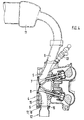
- Fig. 4
- einen Querschnitt durch einen Zylinderkopf mit Teilen der Ansauganlage,
- Fig. 5
- eine Ansicht der Anschlußfläche für das Abgasrückführungs- bzw. Sekundärluftventil.
Rückführung von Abgas in den Ansaugtrakt führt zu der zuvor beschriebenen und an sich bekannten Verbesserung des Abgasverhaltens.
Claims (10)
- Mehrzylindrige Brennkraftmaschine mit einem Ansaug- und einem Abgassystem, einer Zuführeinrichtung für Sekundärluft in das Abgassystem und einem Abgasrückführungssystem, mit einem Zylinderkopf (4) mit mindestens einem Auslaßkanal (6) je Zylinder, mit jeweils mindestens einem in den Zylinderkopf integrierten und in den Auslaßkanal mündenden Sekundärkanal (19), und mit mindestens einer Sammelleitung (18), von der die Sekundärkanäle ausgehen, wobei die Sekundärkanäle und die Sammelleitung in Abhängigkeit vom Betriebsbereich der Brennkraftmaschine zur Abgasrückführung in das Ansaugsystem genutzt werden, dadurch gekennzeichnet, daß die Sammelleitung (18) in dem Zylinderkopf (4) der Brennkraftmaschine integriert ist.
- Brennkraftmaschine nach Anspruch 1, dadurch gekennzeichnet, das die Sammelleitung (18) mit einem Sekundärluftventil (29) und einem Abgasrückführungsventil (28) (AGR-Ventil) verbunden ist, daß das Sekundärluftventil andererseits eine Verbindung zur Umgebungsluft hat, und daß das AGR-Ventil andererseits mit dem Saugsystem (9,11) verbunden ist.
- Brennkraftmaschine nach Anspruch 1 oder 2, dadurch gekennzeichnet, daß die Sammelleitung (17, 18) in eine Flanschfläche (13) des Zylinderkopfes (4) eingelassen ist, daß die Flanschfläche zur Anbindung des Abgaskrümmers (12, 16) dient, und daß die Sammelleitung durch eine Anlagefläche (16) des Abgaskrümmers abgedeckt wird.
- Brennkraftmaschine nach einem oder mehreren der vorherigen Ansprüche, dadurch gekennzeichnet, daß von der Sammelleitung (18) ein Verbindungskanal (20, 21) zu den Ventilen ausgeht, und daß der Verbindungskanal zumindest teilweise zwischen zwei Zylinderbohrungen im Zylinderkopf (4) verläuft.
- Brennkraftmaschine nach einem oder mehreren der vorherigen Ansprüche, dadurch gekennzeichnet, daß der Verbindungskanal (20, 21) in eine Gehäuseaussparung (22) im Kurbelgehäuse (1, 2, 3) mündet.
- Brennkraftmaschine nach einem oder mehreren der vorherigen Ansprüche, dadurch gekennzeichnet, daß die Gehäuseaussparung (22) zur Verbindungsfläche des Kurbelgehäuses (1, 2, 3) mit dem Zylinderkopf (4) offen ist.
- Brennkraftmaschine nach einem oder mehreren der vorherigen Ansprüche, dadurch gekennzeichnet, daß das AGR-Ventil (28) und das Sekundärluftventil (29) an der Außenseite des Gehäuses der Brennkraftmaschine angebracht sind.
- Brennkraftmaschine nach einem oder mehreren der vorherigen Ansprüche, dadurch gekennzeichnet, daß die Ventile (28, 29) an einer gemeinsamen Anschlußfläche (24) am Gehäuse angeordnet sind, und daß von dieser Anschlußfläche Verbindungen (23, 22, 21, 20) zur Sammelleitung und zum Ansaugsystem (9, 11) bestehen.
- Brennkraftmaschine nach einem oder mehreren der vorherigen Ansprüche, dadurch gekennzeichnet, daß zwischen der Gehäuseaussparung (22) im Kurbelgehäuse und der Anschlußfläche (24) eine Verbindungsbohrung (23) verläuft.
- Brennkraftmaschine nach einem oder mehreren der vorherigen Ansprüche, dadurch gekennzeichnet, daß diese zwei Reihen von Zylindern hat, daß von der ersten Reihe von Zylindern die Verbindung zwischen den Sekundärkanälen und den Ventilen vollständig im Gehäuse integriert ist, und daß von den Sekundärkanälen der zweiten Zylinderreihe eine den gehäusefesten Verbindungen nachgeschaltete externe Leitung (27) zu den Ventilen führt.
Applications Claiming Priority (2)
| Application Number | Priority Date | Filing Date | Title |
|---|---|---|---|
| DE4435555 | 1994-10-05 | ||
| DE4435555A DE4435555C1 (de) | 1994-10-05 | 1994-10-05 | Mehrzylindrige Brennkraftmaschine |
Publications (2)
| Publication Number | Publication Date |
|---|---|
| EP0705970A1 EP0705970A1 (de) | 1996-04-10 |
| EP0705970B1 true EP0705970B1 (de) | 2000-06-07 |
Family
ID=6529994
Family Applications (1)
| Application Number | Title | Priority Date | Filing Date |
|---|---|---|---|
| EP95113886A Expired - Lifetime EP0705970B1 (de) | 1994-10-05 | 1995-09-05 | Mehrzylindrige Brennkraftmaschine |
Country Status (4)
| Country | Link |
|---|---|
| US (1) | US5640848A (de) |
| EP (1) | EP0705970B1 (de) |
| JP (1) | JPH08193543A (de) |
| DE (2) | DE4435555C1 (de) |
Families Citing this family (12)
| Publication number | Priority date | Publication date | Assignee | Title |
|---|---|---|---|---|
| DE19621530C1 (de) * | 1996-05-29 | 1997-06-05 | Daimler Benz Ag | Verfahren zur Verminderung der Schadstoffemission einer mehrzylindrigen Brennkraftmaschine |
| DE19757931A1 (de) * | 1997-12-24 | 1999-07-01 | Mannesmann Vdo Ag | Vorrichtung zum Rückführen von Abgas und zum Vorheizen eines Abgasreinigers |
| DE19902678C2 (de) * | 1999-01-23 | 2001-11-15 | Audi Ag | Mehrzylindrige Brennkraftmaschine |
| DE19937781A1 (de) * | 1999-08-10 | 2001-02-15 | Mann & Hummel Filter | Brennkraftmaschine mit Sekundärlufteinblaßsystem |
| DE19959138B4 (de) * | 1999-12-08 | 2014-04-03 | Volkswagen Ag | Vorrichtung zur Abgasrückführung an einer Brennkraftmaschine |
| DE10251359B4 (de) * | 2002-11-05 | 2005-01-20 | Daimlerchrysler Ag | Zylinderkopf einer mehrzylindrigen Brennkraftmaschine |
| DE10257064A1 (de) * | 2002-12-06 | 2004-06-24 | Bayerische Motoren Werke Ag | Flüssigkeitsgekühlter, gegossener Zylinderkopf einer mehrzylindrigen Brennkraftmaschine |
| JP2006219984A (ja) * | 2005-02-08 | 2006-08-24 | Nissan Motor Co Ltd | 多気筒内燃機関の排気装置 |
| DE102005049462A1 (de) * | 2005-10-15 | 2007-05-03 | Daimlerchrysler Ag | Brennkraftmaschine mit Abgasrückführung |
| JP4788531B2 (ja) * | 2006-09-01 | 2011-10-05 | 日産自動車株式会社 | エンジンの制御装置 |
| JP2010096076A (ja) * | 2008-10-16 | 2010-04-30 | Daihatsu Motor Co Ltd | 内燃機関の排気ガス還流装置 |
| EP2627884B1 (de) * | 2010-10-14 | 2014-12-17 | Daimler AG | Brennkraftmaschine sowie verfahren zum herstellen einer solchen brennkraftmaschine |
Family Cites Families (10)
| Publication number | Priority date | Publication date | Assignee | Title |
|---|---|---|---|---|
| JPS549651B2 (de) * | 1974-12-28 | 1979-04-26 | ||
| JPS5273231A (en) * | 1975-12-17 | 1977-06-18 | Toyota Motor Corp | Internal combustion engines for vehicles |
| JPS5337232A (en) * | 1976-09-17 | 1978-04-06 | Toyota Motor Corp | Recirculating device of exhaust gas for internal combustion engine |
| IT1107178B (it) * | 1978-03-23 | 1985-11-25 | Fiat Spa | Motore a combustione interna munito di sistema di controllo dell emissione di gas nocivi |
| JPS618202Y2 (de) * | 1979-07-30 | 1986-03-13 | ||
| JPS5793616A (en) * | 1980-12-03 | 1982-06-10 | Honda Motor Co Ltd | Exhaust purifier for internal combustion engine |
| US4492209A (en) * | 1981-06-05 | 1985-01-08 | Honda Giken Kogyo Kabushiki Kaisha | Exhaust gas recirculation system |
| JPS5929738A (ja) * | 1982-08-11 | 1984-02-17 | Tokyo Roki Kk | 排気ガス浄化装置 |
| FR2655382B1 (fr) * | 1989-12-04 | 1992-04-17 | Peugeot | Dispositif d'introduction de gaz additionnel, tel que de l'air, dans un moteur a combustion interne et moteur equipe d'un tel dispositif. |
| FR2696787B1 (fr) * | 1992-10-09 | 1994-11-25 | Renault | Dispositif d'introduction de gaz additionnels pour moteur à combustion interne. |
-
1994
- 1994-10-05 DE DE4435555A patent/DE4435555C1/de not_active Expired - Lifetime
-
1995
- 1995-09-05 DE DE59508450T patent/DE59508450D1/de not_active Expired - Lifetime
- 1995-09-05 EP EP95113886A patent/EP0705970B1/de not_active Expired - Lifetime
- 1995-09-28 US US08/535,824 patent/US5640848A/en not_active Expired - Lifetime
- 1995-10-04 JP JP7257812A patent/JPH08193543A/ja active Pending
Also Published As
| Publication number | Publication date |
|---|---|
| EP0705970A1 (de) | 1996-04-10 |
| DE59508450D1 (de) | 2000-07-13 |
| US5640848A (en) | 1997-06-24 |
| JPH08193543A (ja) | 1996-07-30 |
| DE4435555C1 (de) | 1996-03-14 |
Similar Documents
| Publication | Publication Date | Title |
|---|---|---|
| DE2353908C3 (de) | Mehrzylindrische Verbrennungskraftmaschine | |
| DE60111744T2 (de) | Brennkraftmaschine mit abgasrückführung | |
| EP1065350B1 (de) | Brennkraftmaschine mit einer Entlüftungseinrichtung | |
| EP0705970B1 (de) | Mehrzylindrige Brennkraftmaschine | |
| DE102014100739B4 (de) | Teilweise integrierter abgaskrümmer | |
| DE19531875C1 (de) | Zylinderkopf für eine flüssigkeitsgekühlte, mehrzylindrische Brennkraftmaschine | |
| DE102011078929A1 (de) | Motor mit Zylinderkopfkühlung | |
| EP1660771A1 (de) | Luftansaugkanalsystem für eine verbrennungskraftmaschine | |
| DE102009042335A1 (de) | Resonator und Kurbelgehäuse-Entlüftungssystem für Verbrennungsmotor | |
| DE2353925A1 (de) | Vorrichtung und verfahren zur ueberwachung und steuerung von verunreinigungen | |
| DE3139309A1 (de) | Brennkraftmaschine | |
| DE3921662C1 (de) | ||
| DE19941863A1 (de) | Ansaugsystem für einen Verbrennungsmotor | |
| EP0251159B1 (de) | Rückführleitung für Leckgase aus dem Kurbelgehäuse | |
| EP0104524B1 (de) | Einrichtung zum Rückführen von Abgas einer Brennkraftmaschine | |
| DE102016010267B4 (de) | Auslassvorrichtung für einen Motor | |
| DE60033057T2 (de) | Integriertes luft-brennstoff-modul mit niedrigen brennstoff-gas-emissionen | |
| EP0855502A2 (de) | Brennkraftmaschine mit Abgasrückführungsvorrichtung | |
| EP2077386B1 (de) | Zylinderkopf mit im Zylinderkopf integriertem Abgaskrümmer | |
| DE102017207363A1 (de) | Verbrennungsmotor-zylinderkopf mit integriertem abgaskrümmer mit mehreren kanälen und mehreren anschlüssen | |
| DE3137453C2 (de) | Ansauganordnung für eine Brennkraftmaschine | |
| DE2617245C2 (de) | Abgasreinigungsanlage für eine Viertakt-Brennkraftmaschine | |
| DE3923924C2 (de) | Steuervorrichtung für das Saugrohrsystem einer Fahrzeugbrennkraftmaschine | |
| DE19811782A1 (de) | Brennkraftmaschine mit zwei Abgasturboladern | |
| EP2077385B1 (de) | Zylinderkopf für eine Brennkraftmaschine mit angrenzendem Bauteil |
Legal Events
| Date | Code | Title | Description |
|---|---|---|---|
| PUAI | Public reference made under article 153(3) epc to a published international application that has entered the european phase |
Free format text: ORIGINAL CODE: 0009012 |
|
| AK | Designated contracting states |
Kind code of ref document: A1 Designated state(s): DE FR GB IT SE |
|
| 17P | Request for examination filed |
Effective date: 19960905 |
|
| 17Q | First examination report despatched |
Effective date: 19980807 |
|
| GRAG | Despatch of communication of intention to grant |
Free format text: ORIGINAL CODE: EPIDOS AGRA |
|
| GRAG | Despatch of communication of intention to grant |
Free format text: ORIGINAL CODE: EPIDOS AGRA |
|
| GRAH | Despatch of communication of intention to grant a patent |
Free format text: ORIGINAL CODE: EPIDOS IGRA |
|
| GRAH | Despatch of communication of intention to grant a patent |
Free format text: ORIGINAL CODE: EPIDOS IGRA |
|
| ITF | It: translation for a ep patent filed | ||
| GRAG | Despatch of communication of intention to grant |
Free format text: ORIGINAL CODE: EPIDOS AGRA |
|
| GRAA | (expected) grant |
Free format text: ORIGINAL CODE: 0009210 |
|
| AK | Designated contracting states |
Kind code of ref document: B1 Designated state(s): DE FR GB IT SE |
|
| REF | Corresponds to: |
Ref document number: 59508450 Country of ref document: DE Date of ref document: 20000713 |
|
| ET | Fr: translation filed | ||
| GBT | Gb: translation of ep patent filed (gb section 77(6)(a)/1977) |
Effective date: 20000717 |
|
| PLBE | No opposition filed within time limit |
Free format text: ORIGINAL CODE: 0009261 |
|
| STAA | Information on the status of an ep patent application or granted ep patent |
Free format text: STATUS: NO OPPOSITION FILED WITHIN TIME LIMIT |
|
| 26N | No opposition filed | ||
| REG | Reference to a national code |
Ref country code: GB Ref legal event code: IF02 |
|
| REG | Reference to a national code |
Ref country code: FR Ref legal event code: TP |
|
| REG | Reference to a national code |
Ref country code: FR Ref legal event code: CD |
|
| REG | Reference to a national code |
Ref country code: FR Ref legal event code: TP |
|
| REG | Reference to a national code |
Ref country code: GB Ref legal event code: 732E Free format text: REGISTERED BETWEEN 20110310 AND 20110316 |
|
| REG | Reference to a national code |
Ref country code: GB Ref legal event code: 732E Free format text: REGISTERED BETWEEN 20110331 AND 20110406 |
|
| PGFP | Annual fee paid to national office [announced via postgrant information from national office to epo] |
Ref country code: DE Payment date: 20140815 Year of fee payment: 20 |
|
| PGFP | Annual fee paid to national office [announced via postgrant information from national office to epo] |
Ref country code: FR Payment date: 20140919 Year of fee payment: 20 Ref country code: GB Payment date: 20140919 Year of fee payment: 20 Ref country code: SE Payment date: 20140918 Year of fee payment: 20 |
|
| PGFP | Annual fee paid to national office [announced via postgrant information from national office to epo] |
Ref country code: IT Payment date: 20140929 Year of fee payment: 20 |
|
| REG | Reference to a national code |
Ref country code: DE Ref legal event code: R071 Ref document number: 59508450 Country of ref document: DE |
|
| REG | Reference to a national code |
Ref country code: GB Ref legal event code: PE20 Expiry date: 20150904 |
|
| PG25 | Lapsed in a contracting state [announced via postgrant information from national office to epo] |
Ref country code: GB Free format text: LAPSE BECAUSE OF EXPIRATION OF PROTECTION Effective date: 20150904 |
|
| REG | Reference to a national code |
Ref country code: SE Ref legal event code: EUG |