EP0706023A1 - Dispositif avec un faux de transfert cyclique élevé - Google Patents
Dispositif avec un faux de transfert cyclique élevé Download PDFInfo
- Publication number
- EP0706023A1 EP0706023A1 EP95202688A EP95202688A EP0706023A1 EP 0706023 A1 EP0706023 A1 EP 0706023A1 EP 95202688 A EP95202688 A EP 95202688A EP 95202688 A EP95202688 A EP 95202688A EP 0706023 A1 EP0706023 A1 EP 0706023A1
- Authority
- EP
- European Patent Office
- Prior art keywords
- pawl
- chain
- pawls
- track
- cam arm
- Prior art date
- Legal status (The legal status is an assumption and is not a legal conclusion. Google has not performed a legal analysis and makes no representation as to the accuracy of the status listed.)
- Withdrawn
Links
Images

Classifications
-
- F—MECHANICAL ENGINEERING; LIGHTING; HEATING; WEAPONS; BLASTING
- F41—WEAPONS
- F41A—FUNCTIONAL FEATURES OR DETAILS COMMON TO BOTH SMALLARMS AND ORDNANCE, e.g. CANNONS; MOUNTINGS FOR SMALLARMS OR ORDNANCE
- F41A9/00—Feeding or loading of ammunition; Magazines; Guiding means for the extracting of cartridges
- F41A9/01—Feeding of unbelted ammunition
- F41A9/06—Feeding of unbelted ammunition using cyclically moving conveyors, i.e. conveyors having ammunition pusher or carrier elements which are emptied or disengaged from the ammunition during the return stroke
Definitions
- the present invention provides a high cycle rate transfer device for material handling.
- the device employs cams and connections with a plurality of pawls moving continuously to transfer materials.
- the invention provides a high cycle and energy efficient material transfer system which is operable in a limited space envelope.
- the high cycle rate transfer device utilizes a fixed length chain with a folding pawl on each end.
- the chain has outboard rollers which run in a track to provide lateral support and is driven by a sprocket.
- a sprocket When the sprocket is driven one pawl unfolds to urge the material while the other paw is folded in, and temporarily out of the way, to let the material through.
- the folding and unfolding mechanisms keep the pawls in a proper position and in a timed relation to each other.
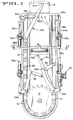
- Figure 1 is a side elevation view of the high cycle rate transfer device showing material (rounds of ammunition) being transferred from a lower position to a final hoisted position. Pawls are shown in extended and unfolded position. The paw on the right is also shown in its folded and stowed position (phantom lines).
- Figure 2 is a section taken along line 2-2 of Figure 1, showing a portion of a magazine drum and a plan view of the high cycle rate transfer device. Rounds are shown in the magazine with one round loaded in the upper hoist tube.
- FIG. 1 A roller chain 10 is driven by sprocket 12. Pawls 14a and 14b are attached at the ends of chain 10. Outboard rollers on chain 10 run in track 16. Support links 18a and 18b at each of pawls 14a and 14b respectively, provide support and slidably engage track 16. Cam arms 22a and 22b are in temporal contact with support links 18a and 18b. Further, support links 18a and 18b are fitted with a roller on the outboard end that is guided by chain track 16. Cam arms 22a and 22b are connected to adjustable rod 24a and 24b. Adjustable rods 24a and 24b are controlled by upper control cable mount 26. Lower control cable mount 26a connects cam arm control cable 28a with paw control arm 34a.
- pawl control actuator 30 connects to cam arm control cable 28b and pawl control arm 34b.
- Pawl control arms 34a and 34b are flexibly connected by arm connection link 36. Restrainer section 38 prevents pawl control arm 34a from extending beyond a preset limit position.
- Pawls 14a and 14b include guide pins 40a and 40b. Further, pawls 14a and 14b include soft cushions or non-metallic tips 41a and 41b as shown. Hoist tube 42 is shown in which rounds are transferred to be supported and pushed by pawls 14a and 14b.
- rounds R1, R2 and R3 are shown in loader structure 43.
- Round R2 is transferred into hoist tube 42 where it is eccentrically positioned relative to pawls 14a and 14b.
- Round R2 is transferred into hoist tube 42 through shutters 44a and 44b.
- Figure 2 shows cam control cables 28a and 28b.
- Sensors/receivers 52a and 52b are placed as shown to detect the presence of a round in hoist tube 42.
- Loader structure 43 forms the outer boundary of loader drum 54 where rounds are stored to be transferred. Also rounds in hoist tube 42 may be removed via access door 56.
- the disclosure herein above relates to some of the most important structural features and operational parameters for the high cycle rate transfer device.
- the operation of the device under a best mode scenario is described herein below.
- the present invention is coupled to an ammunition magazine drum from where rounds of ammunition are to be hoisted to an upper gun chamber. Accordingly, the high cycle rate transfer device accepts the round at a lower level and raises it up to the gun chamber. Similarly, ammunition or any other material could be hoisted from a lower level to a desired higher level using the device disclosed herein.
- pawl 14a is shown in the up position and paw 14b is shown in an extended position.
- pawls 14a and 14b stow into track 16 (shown in phantom lines).
- pawl 14a will be retracted and stored into track 16 as it moves down, (similar to that shown on the phantom line for pawl 14b).
- Retraction of either pawl 14a or 14b is accomplished in exactly the same manner. For example the retraction of pawl 14a is accomplished by preventing the left end support link 18a from moving using cam arm 22a as the pawl is lowered.
- pawl control actuator 30 is required to position all the mechanisms controlling the relative positions of pawls 14a and 14b.
- Hydraulic pressure is applied to the upper end of actuator 30, and a spool moves downward overcoming a spring energized spool locking detent.
- pawl support link 18a or 18b (depending upon which pawl is being raised) rotates downward (clockwise on 18a if pawl 14a is being raised) until it stops against the edge surface of the pawl being raised. This forms a rigid structure with which to push round R.
- pawl support link 18a or 18b is maintained at 80° angle with pawl 14a or 14b, respectively.
- This design feature enables connection link 36 and associated linkage to retract pawl 14a or 14b and allow rounds of ammunition to be lowered back down from the transfer station into the loader outer structure 43.
- rounds of ammunition referred to as R1, R2, and R3 are placed into loader drum 54 by another mechanism (not shown).
- a mechanism inside loader drum 54 pushes the round in the direction shown through shutters 44a and 44b, and into hoist tube 42.
- Shutters 44a and 44b are cammed open by the round in the direction shown by the arrows and are spring-returned to their original position once the round is fully into hoist tube 42.
- Pawls 14a and 14b, which raise the round in hoist tube 42, are positioned below in order to urge the round upwards inside hoist tube 42.
- pawls 14a or 14b is located immediately below the round to be hoisted such that when the pawls are moved the round is pushed upwards inside hoist tube 42. As pawls 14a or 14b are pushed by chain 10 they move through a slot in the floor between track 16 and come in contact with the round to be hoisted. In the interest of simplicity, pawls 14a and 14b are not shown in Figure 2. Once the round is in hoist tube 42, the round must be either hoisted or removed via access door 56.
- the centerline of chain 10 and track 16 is offset from the center of hoist tube 42. This is primarily to avoid contact of pawls 14a and 14b with the primer.
- the primer is what initiates detonation and is centrally located at the bottom of the round.
- pawls 14a and 14b include non-metallic tips 41a and 41b (refer to Figure 1) which cushion the contact between the round being hoisted and the pawl in contact therewith.
- the high cycle rate transfer device disclosed herein does not require a retraction cycle which requires both energy and time. Instead, the present invention provides a high cycle rate by allowing two pawls to consecutively move material without the need for a retraction cycle. In essence, the present invention provides a continuous transfer of material with a single drive and actuator.
Landscapes
- Engineering & Computer Science (AREA)
- General Engineering & Computer Science (AREA)
- Load-Engaging Elements For Cranes (AREA)
- Transmission Devices (AREA)
Applications Claiming Priority (2)
| Application Number | Priority Date | Filing Date | Title |
|---|---|---|---|
| US317623 | 1981-11-02 | ||
| US08/317,623 US5553699A (en) | 1994-10-06 | 1994-10-06 | High cycle rate transfer device |
Publications (1)
| Publication Number | Publication Date |
|---|---|
| EP0706023A1 true EP0706023A1 (fr) | 1996-04-10 |
Family
ID=23234517
Family Applications (1)
| Application Number | Title | Priority Date | Filing Date |
|---|---|---|---|
| EP95202688A Withdrawn EP0706023A1 (fr) | 1994-10-06 | 1995-10-06 | Dispositif avec un faux de transfert cyclique élevé |
Country Status (2)
| Country | Link |
|---|---|
| US (1) | US5553699A (fr) |
| EP (1) | EP0706023A1 (fr) |
Citations (5)
| Publication number | Priority date | Publication date | Assignee | Title |
|---|---|---|---|---|
| US3136212A (en) * | 1952-08-27 | 1964-06-09 | Philias H Girouard | Empty case ejector for automatic gun systems |
| BE656348A (fr) * | 1963-11-28 | 1965-03-16 | ||
| EP0058814A2 (fr) * | 1981-02-19 | 1982-09-01 | Fmc Corporation | Système de chargement vertical pour canon |
| US4481862A (en) * | 1982-07-13 | 1984-11-13 | Fmc Corporation | Automatic loading system for fixed ammunition at gun elevation |
| US4640182A (en) * | 1983-11-04 | 1987-02-03 | Ares, Inc. | Shell feeding apparatus for guns |
Family Cites Families (4)
| Publication number | Priority date | Publication date | Assignee | Title |
|---|---|---|---|---|
| US2526847A (en) * | 1946-08-19 | 1950-10-24 | Vickers Armstrongs Ltd | Hoist for conveying loads to moving platforms |
| US3200930A (en) * | 1964-01-03 | 1965-08-17 | Cons Cigar Corp | Article feeding apparatus |
| US4403482A (en) * | 1981-05-01 | 1983-09-13 | Jackstone Froster Limited | Automatic plate freezers |
| DE9306508U1 (de) * | 1993-04-30 | 1993-07-01 | Paper Converting Machine Gmbh, 6707 Schifferstadt | Vorrichtung zum Transport von Produkten |
-
1994
- 1994-10-06 US US08/317,623 patent/US5553699A/en not_active Expired - Lifetime
-
1995
- 1995-10-06 EP EP95202688A patent/EP0706023A1/fr not_active Withdrawn
Patent Citations (5)
| Publication number | Priority date | Publication date | Assignee | Title |
|---|---|---|---|---|
| US3136212A (en) * | 1952-08-27 | 1964-06-09 | Philias H Girouard | Empty case ejector for automatic gun systems |
| BE656348A (fr) * | 1963-11-28 | 1965-03-16 | ||
| EP0058814A2 (fr) * | 1981-02-19 | 1982-09-01 | Fmc Corporation | Système de chargement vertical pour canon |
| US4481862A (en) * | 1982-07-13 | 1984-11-13 | Fmc Corporation | Automatic loading system for fixed ammunition at gun elevation |
| US4640182A (en) * | 1983-11-04 | 1987-02-03 | Ares, Inc. | Shell feeding apparatus for guns |
Also Published As
| Publication number | Publication date |
|---|---|
| US5553699A (en) | 1996-09-10 |
Similar Documents
| Publication | Publication Date | Title |
|---|---|---|
| GB2081671A (en) | Crane boom extending retracting and cooperative latching arrangement | |
| EP0569546B1 (fr) | Systeme pour la manutention de la cargaison d'un avion | |
| SU1207392A3 (ru) | Судова аппарель | |
| JP3867826B2 (ja) | 把持装置 | |
| US4759673A (en) | Apparatus for enabling transit of articles between adjacent surfaces | |
| CA2005148C (fr) | Methode et appareil de depliage d'elements de pneus | |
| US4142640A (en) | Device for retracting or extending a movable access ramp | |
| AU6346798A (en) | Stowed platform wheelchair lifter | |
| US12313368B2 (en) | Storage and loading system for large caliber ammunition | |
| ITTO951046A1 (it) | Tamburo di formatura di pneumatici | |
| US5440985A (en) | Delivery system for printing plate | |
| US6345855B2 (en) | Level floor room extension | |
| US5553699A (en) | High cycle rate transfer device | |
| US5363527A (en) | Spanning beam structure for clearing breaches by vehicles | |
| GB2200613A (en) | A conveyor system | |
| US4193439A (en) | Device for operating hatch covers or the like composed of panels | |
| RU1838691C (ru) | Устройство дл креплени р да соединительных скоб на конце транспортерной ленты | |
| EP0745544A1 (fr) | Dispositif pour vider un récipient à ordures dans la benne d'un véhicule de ramassage d'ordures | |
| GB2075567A (en) | Telescopic mast | |
| GB2278337A (en) | Spreader guide apparatus | |
| WO2024157075A1 (fr) | Machine pour l'usinage au laser de tubes et de profilés, en particulier machine pour la découpe au laser de tubes et de profilés, avec un système de déchargement amélioré pour décharger le tube ou le profilé à la fin du processus d'usinage | |
| KR102367015B1 (ko) | 차량 루프용 다관절 승하강 캐리어 | |
| JP2671102B2 (ja) | 伸縮ポール | |
| CN117090520A (zh) | 矩阵式钻杆储存系统与输送系统 | |
| US11078995B2 (en) | Apparatus for converting motion |
Legal Events
| Date | Code | Title | Description |
|---|---|---|---|
| PUAI | Public reference made under article 153(3) epc to a published international application that has entered the european phase |
Free format text: ORIGINAL CODE: 0009012 |
|
| 17P | Request for examination filed |
Effective date: 19951006 |
|
| AK | Designated contracting states |
Kind code of ref document: A1 Designated state(s): DE GB IT SE |
|
| 17Q | First examination report despatched |
Effective date: 19981124 |
|
| STAA | Information on the status of an ep patent application or granted ep patent |
Free format text: STATUS: THE APPLICATION IS DEEMED TO BE WITHDRAWN |
|
| 18D | Application deemed to be withdrawn |
Effective date: 19990407 |