EP0706078B1 - Einspannvorrichtung für Rollenmaterial - Google Patents
Einspannvorrichtung für Rollenmaterial Download PDFInfo
- Publication number
- EP0706078B1 EP0706078B1 EP95112949A EP95112949A EP0706078B1 EP 0706078 B1 EP0706078 B1 EP 0706078B1 EP 95112949 A EP95112949 A EP 95112949A EP 95112949 A EP95112949 A EP 95112949A EP 0706078 B1 EP0706078 B1 EP 0706078B1
- Authority
- EP
- European Patent Office
- Prior art keywords
- clamping device
- clamping
- roll
- roll material
- cutting
- Prior art date
- Legal status (The legal status is an assumption and is not a legal conclusion. Google has not performed a legal analysis and makes no representation as to the accuracy of the status listed.)
- Expired - Lifetime
Links
Images
Classifications
-
- B—PERFORMING OPERATIONS; TRANSPORTING
- B65—CONVEYING; PACKING; STORING; HANDLING THIN OR FILAMENTARY MATERIAL
- B65H—HANDLING THIN OR FILAMENTARY MATERIAL, e.g. SHEETS, WEBS, CABLES
- B65H35/00—Delivering articles from cutting or line-perforating machines; Article or web delivery apparatus incorporating cutting or line-perforating devices, e.g. adhesive tape dispensers
- B65H35/04—Delivering articles from cutting or line-perforating machines; Article or web delivery apparatus incorporating cutting or line-perforating devices, e.g. adhesive tape dispensers from or with transverse cutters or perforators
- B65H35/06—Delivering articles from cutting or line-perforating machines; Article or web delivery apparatus incorporating cutting or line-perforating devices, e.g. adhesive tape dispensers from or with transverse cutters or perforators from or with blade, e.g. shear-blade, cutters or perforators
-
- B—PERFORMING OPERATIONS; TRANSPORTING
- B26—HAND CUTTING TOOLS; CUTTING; SEVERING
- B26D—CUTTING; DETAILS COMMON TO MACHINES FOR PERFORATING, PUNCHING, CUTTING-OUT, STAMPING-OUT OR SEVERING
- B26D7/00—Details of apparatus for cutting, cutting-out, stamping-out, punching, perforating, or severing by means other than cutting
- B26D7/08—Means for treating work or cutting member to facilitate cutting
- B26D7/14—Means for treating work or cutting member to facilitate cutting by tensioning the work
-
- G—PHYSICS
- G03—PHOTOGRAPHY; CINEMATOGRAPHY; ANALOGOUS TECHNIQUES USING WAVES OTHER THAN OPTICAL WAVES; ELECTROGRAPHY; HOLOGRAPHY
- G03B—APPARATUS OR ARRANGEMENTS FOR TAKING PHOTOGRAPHS OR FOR PROJECTING OR VIEWING THEM; APPARATUS OR ARRANGEMENTS EMPLOYING ANALOGOUS TECHNIQUES USING WAVES OTHER THAN OPTICAL WAVES; ACCESSORIES THEREFOR
- G03B27/00—Photographic printing apparatus
- G03B27/32—Projection printing apparatus, e.g. enlarger, copying camera
- G03B27/52—Details
- G03B27/58—Baseboards, masking frames, or other holders for the sensitive material
- G03B27/587—Handling photosensitive webs
- G03B27/588—Supply rolls; Cutting arrangements
-
- Y—GENERAL TAGGING OF NEW TECHNOLOGICAL DEVELOPMENTS; GENERAL TAGGING OF CROSS-SECTIONAL TECHNOLOGIES SPANNING OVER SEVERAL SECTIONS OF THE IPC; TECHNICAL SUBJECTS COVERED BY FORMER USPC CROSS-REFERENCE ART COLLECTIONS [XRACs] AND DIGESTS
- Y10—TECHNICAL SUBJECTS COVERED BY FORMER USPC
- Y10S—TECHNICAL SUBJECTS COVERED BY FORMER USPC CROSS-REFERENCE ART COLLECTIONS [XRACs] AND DIGESTS
- Y10S83/00—Cutting
- Y10S83/929—Particular nature of work or product
- Y10S83/948—Particular nature of work or product having "memory", e.g. photographic or magnetic film
-
- Y—GENERAL TAGGING OF NEW TECHNOLOGICAL DEVELOPMENTS; GENERAL TAGGING OF CROSS-SECTIONAL TECHNOLOGIES SPANNING OVER SEVERAL SECTIONS OF THE IPC; TECHNICAL SUBJECTS COVERED BY FORMER USPC CROSS-REFERENCE ART COLLECTIONS [XRACs] AND DIGESTS
- Y10—TECHNICAL SUBJECTS COVERED BY FORMER USPC
- Y10T—TECHNICAL SUBJECTS COVERED BY FORMER US CLASSIFICATION
- Y10T83/00—Cutting
- Y10T83/323—With means to stretch work temporarily
-
- Y—GENERAL TAGGING OF NEW TECHNOLOGICAL DEVELOPMENTS; GENERAL TAGGING OF CROSS-SECTIONAL TECHNOLOGIES SPANNING OVER SEVERAL SECTIONS OF THE IPC; TECHNICAL SUBJECTS COVERED BY FORMER USPC CROSS-REFERENCE ART COLLECTIONS [XRACs] AND DIGESTS
- Y10—TECHNICAL SUBJECTS COVERED BY FORMER USPC
- Y10T—TECHNICAL SUBJECTS COVERED BY FORMER US CLASSIFICATION
- Y10T83/00—Cutting
- Y10T83/444—Tool engages work during dwell of intermittent workfeed
- Y10T83/445—With work-moving clamp jaw
-
- Y—GENERAL TAGGING OF NEW TECHNOLOGICAL DEVELOPMENTS; GENERAL TAGGING OF CROSS-SECTIONAL TECHNOLOGIES SPANNING OVER SEVERAL SECTIONS OF THE IPC; TECHNICAL SUBJECTS COVERED BY FORMER USPC CROSS-REFERENCE ART COLLECTIONS [XRACs] AND DIGESTS
- Y10—TECHNICAL SUBJECTS COVERED BY FORMER USPC
- Y10T—TECHNICAL SUBJECTS COVERED BY FORMER US CLASSIFICATION
- Y10T83/00—Cutting
- Y10T83/444—Tool engages work during dwell of intermittent workfeed
- Y10T83/4645—With means to clamp work during dwell
-
- Y—GENERAL TAGGING OF NEW TECHNOLOGICAL DEVELOPMENTS; GENERAL TAGGING OF CROSS-SECTIONAL TECHNOLOGIES SPANNING OVER SEVERAL SECTIONS OF THE IPC; TECHNICAL SUBJECTS COVERED BY FORMER USPC CROSS-REFERENCE ART COLLECTIONS [XRACs] AND DIGESTS
- Y10—TECHNICAL SUBJECTS COVERED BY FORMER USPC
- Y10T—TECHNICAL SUBJECTS COVERED BY FORMER US CLASSIFICATION
- Y10T83/00—Cutting
- Y10T83/748—With work immobilizer
- Y10T83/7487—Means to clamp work
- Y10T83/7533—With biasing or counterbalancing means
-
- Y—GENERAL TAGGING OF NEW TECHNOLOGICAL DEVELOPMENTS; GENERAL TAGGING OF CROSS-SECTIONAL TECHNOLOGIES SPANNING OVER SEVERAL SECTIONS OF THE IPC; TECHNICAL SUBJECTS COVERED BY FORMER USPC CROSS-REFERENCE ART COLLECTIONS [XRACs] AND DIGESTS
- Y10—TECHNICAL SUBJECTS COVERED BY FORMER USPC
- Y10T—TECHNICAL SUBJECTS COVERED BY FORMER US CLASSIFICATION
- Y10T83/00—Cutting
- Y10T83/889—Tool with either work holder or means to hold work supply
- Y10T83/896—Rotatable wound package supply
Definitions
- the present invention relates to a clamping device for roll material, especially for image exposure devices, according to the preamble of claim 1 (EP-A-0 082 474).
- Introducing roll material into the exposure zone of a Exposure device is usually done by driving the Roll material previously cut off at right angles.
- the exact right-angled cutting of the material and that Even tensioning of the material is important in this no errors occur after a later exposure.
- the roll material does not change during further transport tilt and do not form any irregularities.
- the first edge of the roll material to be inserted is not exact is cut off at right angles, it can be both when tightening of the material as well as later transport Wave formation and canting occur, so that not can be properly exposed and / or that Roll material must be clamped again.
- EP-A-0 300 967 describes a device for the production known from photographic copies.
- a device for Roll material according to the preamble of claim 1 create, with the help of this at right angles to Longitudinal extension of the roller conveyor can be cut and with the simultaneous clamping of the roll material perpendicular to its axis and without canting and Wave formation is possible.
- the first clamping device Since the the first clamping device is movably mounted, there is the great advantage that when clamping the Material web between the first clamping device and Roll holder an automatic compensation of the occurring Material tensions take place so that the material web differs from evenly tensioned. Since the first clamping device too is resilient, there is a good balance of the tensile and shear stresses occurring in the material.
- the resilient mounting of the first clamping device along two axes are not parallel.
- This measure improved again the even tensioning of the material web, because as a result, the material web can be stretched so that the irregularities that occur along the track itself balance the two axes.
- one axis perpendicular and the other axis parallel to the path of the roll material is arranged.
- the material web on the one hand in the direction of Longitudinal extension of the roll material are tensioned, whereby but at the same time in the direction perpendicular to this Compensation takes place. Provided that the roll material by the first Clamping device is clamped and then tensioned is completely automatic Tension of the material web.
- the first clamping device can be an alligator clip, which makes the roll material good during tensioning is held, but after loosening the alligator clip again is completely released.
- the second clamping device acts essentially on the total width of the roll material. This measure will the roll material after it goes through the first Clamping device has been tensioned evenly with this uniform tension fixed along the web width, whereby even if the material is pulled out later Image exposure device maintain the even tension becomes.
- a first Sensor may be provided, which is the first clamping device activated when the roll material has reached it. This only requires the roll material in the Clamping device are introduced, whereupon then at The sensor automatically reaches the first clamping device is operated.
- a second sensor be provided, which is the second clamping device activated when the first clamping device a predetermined Has traveled parallel to the path of the roll material. This will automatically roll the roll material through the second Clamping device in an evenly tensioned state clamped because when tensioning the roll material against the Spring force of the first clamping device is even Material tension sets without wave formation.
- a movable guide plate is provided, on the one hand the introduction of the material web into the first clamping device relieved, on the other hand after pressing the Cutting device the resulting material residue from the Device can be removed easily.
- the roll holder and the second Clamping device can be arranged on a revolver magazine. This allows the roll material after pressing the Cutting device with the help of the revolver magazine move on to an insertion in for example a To enable image exposure device. At the same time everyone can the roll of material provided in a revolver magazine Be brought into the loading position in which the insertion into the Jig is possible.
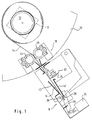
- the clamping device shown in Fig. 1 for Roll material has a roll holder 10 for the Roll core 12 of a material web 14.
- the roll holder 10 is provided with a mechanism for tensioning the Web 14 allowed when the end of the web is fixed.
- the material can be, for example act on exposable photo paper.
- first clamping device 16 and a second Clamping device 18 is provided, the second Clamping device 18 together with the roller holder 10 a rotatable revolver magazine 20 is arranged.
- the first Clamping device 16 is provided in a stationary manner.
- the clamping device Between the first clamping device and the second A cutting device 22 is arranged in the clamping device, whose cutting knife 24 is at right angles to the longitudinal extent the paper web is provided. When pressing the Cutting knife 24, the paper web 14 on its entire Width cut.
- the first comprises Clamping device 16 one via a magnet 25 or one other controllable clamping device actuated, articulated stored clamping lever in the form of an alligator clip 26, the presses against an anvil 28.
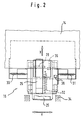
- the first clamping device 16 is resiliently mounted along two axes X and Y, so that these along these axes against the spring force of springs 30, 31 and 32 is freely movable.
- the crocodile clip 26 acts here the first clamping device 16 to the middle of the Roll material 14, which compared to the width of the Material web a "punctiform" clamping area is provided.
- a stop 34 is provided against which the unit from alligator clip 26, anvil 28 and actuating magnet 25 can strike.
- the above is Unit on a cross slide that is both parallel as well perpendicular to the paper web along the X and Y axes the force of the springs 30, 31 and 32 can be moved.
- the free mobility is through Ball bearing linear units guaranteed.
- first clamping device 16 In the area of the first clamping device 16 there is a first one Sensor 36 provided that the first clamping device 16 then activated when the end of the paper web 14 the sensor 36 has reached.
- a second sensor 38 in the form of a Fork light barrier activates the first actuator 18 when the first clamping device 16 has a stroke of 7 mm X direction, which has a clamping force of 25 N. corresponds.
- FIG. 1 also shows, are between the cutting device 22 and the first clamping device 16 two guide plates 40, 42 is provided, the guide plate 42 being pivotally mounted is and can therefore be opened to one cut off the rest of the paper web 14 from the device remove.
- the second clamping device 18, which on the revolver magazine 20th arranged, consists essentially of a Pinch roller pair 44, 46, which extends over the entire width of the Paper web 14 extends.
- the outer surface of the Pinch rollers 44, 46 rubberized, the rubberization being graded is formed, whereby a uniform clamping results.
- the revolver magazine 20 in the loading position can be rotated by appropriate Encodings can be done automatically.
- the Paper web 14 manually or automatically in the second Clamping device 18 introduced i.e. the paper web 14 will passed between the pinch rollers 44 and 46 leading to this Do not exert any clamping force at the time.
- the Insert through guide plates in the second clamping device 18 relieved.
- the paper web 14 through the Cutting device 22 between the guide plates 40, 42 in Direction of the first clamping device 16 moves.
- the sensor 36 triggered, which activates the magnet 25, whereby the Clamping device 16 is actuated, i.e.
- Alligator clip 26 closes and the paper web against the anvil 28 presses. Then the paper web is in the area of Alligator clip 26 is clamped and can be turned by turning the Material roll on the revolver magazine 20 are tensioned. The Clamping can be done manually or automatically.
- the paper web 14 is now stretched until the first clamping device 16 from the stop 34 by 7 mm has moved away, whereby the second sensor 38 is actuated.
- a certain, precisely defined tensile stress acts in this way on the paper web.
- the paper web is in this state due to the resilient mounting of the clamping device 16 absolutely evenly tensioned without any wave formation or Canting occurs.
- the second sensor 38 now activates the second clamping device 18, i.e. the two pinch rollers 44 and 46 are actuated so that the paper web on the one hand between the first and second clamping device, but also between the material roll and the second clamping device 18 is evenly tensioned.
- the Cutting device 23 By pressing the Cutting device 23 is a for the longitudinal extension of the Paper web cut at right angles, whereby an unwinding process perpendicular to the roller conveyor is guaranteed. Then the above Paper web rewound in the revolver magazine and then can the revolver magazine 20 are rotated around the material web 14 to move to another position in which an insertion into an image exposure device. There can then again the paper web by means of clamping devices or grippers 14 are pulled out of the second clamping device 18. However, at this point the paper web is absolutely is clamped evenly with another Processing the web in the image exposure device no Canting and no wave formation occur. If the Paper web can be inserted into the image exposure device the clamping force between the pinch rollers 44 and 46 slightly be reduced. Then, by moving Guide plate 42 the cut paper residue from the Device are removed.
Landscapes
- Life Sciences & Earth Sciences (AREA)
- Forests & Forestry (AREA)
- Engineering & Computer Science (AREA)
- Mechanical Engineering (AREA)
- Physics & Mathematics (AREA)
- General Physics & Mathematics (AREA)
- Advancing Webs (AREA)
- Replacement Of Web Rolls (AREA)
- Unwinding Webs (AREA)
- Casting Or Compression Moulding Of Plastics Or The Like (AREA)
- Milling Processes (AREA)
- Rolls And Other Rotary Bodies (AREA)
- Details Of Cutting Devices (AREA)
- Winding, Rewinding, Material Storage Devices (AREA)
- Surgical Instruments (AREA)
- Light Sources And Details Of Projection-Printing Devices (AREA)
Description
Claims (13)
- Einspannvorrichtung für Rollenmaterial, insbesondere für Bildbelichtungsgeräte, miteiner Rollenhalterung (10) zum Lagern einer Rolle von Rollenmaterial;einer ersten Klemmeinrichtung (16) zum Klemmen eines abgerollten Endes vom Rollenmaterial;einer zweiten Klemmeinrichtung (18) zum Klemmen des Rollenmaterials zwischen der Rollenhalterung und der ersten Klemmeinrichtung; undeiner zwischen den Klemmeinrichtungen angeordneten Schneideinrichtung (22) zum rechtwinklichen Abschneiden des von der ersten und zweiten Klemmeinrichtung geklemmten und gespannten Rollenmaterials,
dadurch gekennzeichnet, daß
die erste Klemmeinrichtung (16) beweglich und federnd gelagert ist. - Vorrichtung nach Anspruch 1, dadurch gekennzeichnet, daß sich die erste Kleinmeinrichtung (16) selbsttätig mittig zum Rollenmaterial zentriert.
- Vorrichtung nach Anspruch 1 oder 2, dadurch gekennzeichnet, daß die federnde Lagerung entlang zweier nicht paralleler Achsen (X, Y) erfolgt.
- Vorrichtung nach Anspruch 3, dadurch gekennzeichnet, daß eine Achse (Y) senkrecht und die andere Achse (X) parallel zur Bahn (14) des Rollenmaterials angeordnet ist.
- Vorrichtung nach zumindest einem der vorstehenden Ansprüche, dadurch gekennzeichnet, daß die erste Klemmeinrichtung (16) auf die Mitte des Rollenmaterials (14) wirkt.
- Vorrichtung nach zumindest einem der vorstehenden Ansprüche, dadurch gekennzeichnet, daß die erste Klemmeinrichtung eine Krokodilklemme (26) aufweist.
- Vorrichtung nach zumindest einem der vorstehenden Ansprüche, dadurch gekennzeichnet, daß die zweite Klemmeinrichtung (18) auf im wesentlichen die gesamte Breite des Rollenmaterials (14) wirkt.
- Vorrichtung nach Anspruch 7, dadurch gekennzeichnet, daß die zweite Klemmeinrichtung ein Klemmrollenpaar (44, 46) ist.
- Vorrichtung nach zumindest einem der vorstehenden Ansprüche, dadurch gekennzeichnet, daß ein erster Sensor (36) vorgesehen ist, der die erste Klemmeinrichtung dann aktiviert, wenn das Rollenmaterial diese erreicht hat.
- Vorrichtung nach Anspruch 9, dadurch gekennzeichnet, daß ein zweiter Sensor (38) vorgesehen ist, der die zweite Klemmeinrichtung (18) dann aktiviert, wenn die erste Klemmeinrichtung (16) einen vorgegebenen Weg parallel zur Bahn des Rollenmaterials (14) zurückgelegt hat.
- Vorrichtung nach zumindest einem der vorstehenden Ansprüche, dadurch gekennzeichnet, daß zwischen Schneideinrichtung (22) und erster Klemmeinrichtung (16) ein bewegbares Führungsblech (42) vorgesehen ist.
- Vorrichtung nach zumindest einem der vorstehenden Ansprüche, dadurch gekennzeichnet, daß die Klemmeinrichtungen mittels Magneten (25) aktivierbar sind.
- Vorrichtung nach zumindest einem der vorstehenden Ansprüche, dadurch gekennzeichnet, daß die Rollenhalterung (10) und die zweite Klemmeinrichtung (18) an einem Revolvermagazin (20) angeordnet sind.
Applications Claiming Priority (2)
| Application Number | Priority Date | Filing Date | Title |
|---|---|---|---|
| IT94BZ000056A IT1278337B1 (it) | 1994-09-19 | 1994-09-19 | Disposizione per la messa in tensione di materiale bobinato. |
| ITBZ940056 | 1994-09-19 |
Publications (2)
| Publication Number | Publication Date |
|---|---|
| EP0706078A1 EP0706078A1 (de) | 1996-04-10 |
| EP0706078B1 true EP0706078B1 (de) | 2000-11-15 |
Family
ID=11346666
Family Applications (1)
| Application Number | Title | Priority Date | Filing Date |
|---|---|---|---|
| EP95112949A Expired - Lifetime EP0706078B1 (de) | 1994-09-19 | 1995-08-17 | Einspannvorrichtung für Rollenmaterial |
Country Status (9)
| Country | Link |
|---|---|
| US (1) | US5823083A (de) |
| EP (1) | EP0706078B1 (de) |
| JP (1) | JPH08106131A (de) |
| AT (1) | ATE197648T1 (de) |
| AU (1) | AU689926B2 (de) |
| CA (1) | CA2157629A1 (de) |
| DE (1) | DE59508860D1 (de) |
| ES (1) | ES2153003T3 (de) |
| IT (1) | IT1278337B1 (de) |
Families Citing this family (13)
| Publication number | Priority date | Publication date | Assignee | Title |
|---|---|---|---|---|
| US20040161416A1 (en) * | 1993-12-14 | 2004-08-19 | University Of Pittsburgh Of The Commonwealth System Of Higher Education | Systemic gene treatment of connective tissue diseases |
| EP0936166A1 (de) * | 1998-02-10 | 1999-08-18 | E.I. Du Pont De Nemours And Company | Schneidevorrichtung mit hoher Geschwindigkeit |
| US6170369B1 (en) * | 1998-11-03 | 2001-01-09 | Johns Manville International, Inc. | Portable batt cutter |
| DE60026207T8 (de) * | 1999-07-27 | 2007-03-29 | Noritsu Koki Co., Ltd. | Schneidevorrichtung für blattförmiges gefördertes Material in einem fotografischen Behandlungsgerät |
| US6736348B1 (en) * | 2000-06-28 | 2004-05-18 | Georgia-Pacific Corporation | Power transfer system apparatus |
| US6394384B1 (en) * | 2000-09-06 | 2002-05-28 | Xerox Corporation | Multi-roll media supporting and supply system |
| US6657131B2 (en) * | 2000-12-08 | 2003-12-02 | Intel Corporation | I/C package / thermal-solution retention mechanism with spring effect |
| US7102366B2 (en) * | 2001-02-09 | 2006-09-05 | Georgia-Pacific Corporation | Proximity detection circuit and method of detecting capacitance changes |
| US7017856B2 (en) * | 2001-02-09 | 2006-03-28 | Georgia-Pacific Corporation | Static build-up control in dispensing system |
| US6592067B2 (en) | 2001-02-09 | 2003-07-15 | Georgia-Pacific Corporation | Minimizing paper waste carousel-style dispenser apparatus, sensor, method and system with proximity sensor |
| US7341170B2 (en) * | 2002-03-07 | 2008-03-11 | Georgia-Pacific Consumer Operations Llc | Apparatus and methods usable in connection with dispensing flexible sheet material from a roll |
| US20070194166A1 (en) | 2006-02-18 | 2007-08-23 | Georgia-Pacific Consumer Products Lp | Electronic Dispenser for Dispensing Sheet Products |
| US7878446B2 (en) | 2006-10-20 | 2011-02-01 | Georgia-Pacific Consumer Products Lp | Dispenser housing with motorized roller transport |
Family Cites Families (22)
| Publication number | Priority date | Publication date | Assignee | Title |
|---|---|---|---|---|
| NL6600102A (de) * | 1966-01-05 | 1967-07-06 | ||
| US3457814A (en) * | 1966-09-21 | 1969-07-29 | Jacob Muchnick | Strip severing and stacking device and method |
| US3496811A (en) * | 1968-05-13 | 1970-02-24 | Wagner Research Corp | Apparatus for controlling and exposing the edge of limp material |
| US3701299A (en) * | 1971-03-02 | 1972-10-31 | Stumpf Guenter | Apparatus for forming stacks of cloth webs which are cut to length |
| JPS5316713Y2 (de) * | 1972-12-06 | 1978-05-02 | ||
| GB1444275A (en) * | 1973-08-08 | 1976-07-28 | Metal Box Co Ltd | Web feeding apparatus |
| GB1536054A (en) * | 1975-03-21 | 1978-12-20 | Hoechst Ag | Apparatus for cutting a web of material |
| US3995951A (en) * | 1975-03-26 | 1976-12-07 | Xerox Corporation | Sheet feeding apparatus and reproducing machine |
| DE2544410C3 (de) * | 1975-10-03 | 1979-11-29 | Texpa-Arbter Maschinenbaugesellschaft Mbh, 8741 Saal | Einrichtung zum Ausrichten und fadengeraden Trennen von Stoffbahnen |
| US4077287A (en) * | 1976-10-18 | 1978-03-07 | Boris Anatolievich Makeev | Apparatus for cross cutting coiled strip into rectangular and oblique angled plates and cutting off acute angles |
| JPS58107540A (ja) * | 1981-12-22 | 1983-06-27 | Fuji Photo Film Co Ltd | カメラプロセサにおけるフイルム貯蔵装置 |
| US4488466A (en) * | 1982-09-07 | 1984-12-18 | Seal Tech Corp. | Apparatus for cutting sheet material |
| JPS59139159A (ja) * | 1983-01-28 | 1984-08-09 | Adobuansuto Technol Bijinesu Kurieeshiyon:Kk | テ−プ駆動装置 |
| JPS6019652A (ja) * | 1983-07-14 | 1985-01-31 | Fuji Xerox Co Ltd | ロ−ル紙用カツタ−装置 |
| JPS61197191A (ja) * | 1985-02-22 | 1986-09-01 | 株式会社 竹原機械研究所 | 帯状体の切断装置 |
| ES2034366T3 (es) * | 1987-07-21 | 1993-04-01 | Gretag Aktiengesellschaft | Dispositivo para la realizacion de copias fotograficas. |
| JPS6434195U (de) * | 1987-08-21 | 1989-03-02 | ||
| GB8901184D0 (en) * | 1989-01-19 | 1989-03-15 | Devro Ltd | Sheet dispenser |
| US4932296A (en) * | 1989-01-25 | 1990-06-12 | Boone Everett C | Apparatus for cutting a continuous strip of limp material |
| US5020403A (en) * | 1989-06-20 | 1991-06-04 | Angelo Joseph J D | Web feeding, cutting and dispensing machine |
| US4938907A (en) * | 1989-06-27 | 1990-07-03 | Motorola Inc. | Braided sleeve cutter and method |
| US5153661A (en) * | 1989-12-25 | 1992-10-06 | Dainippon Screen Mfg. Co., Ltd. | Apparatus and method for laser recording of an image with means for feeding a material |
-
1994
- 1994-09-19 IT IT94BZ000056A patent/IT1278337B1/it active IP Right Grant
-
1995
- 1995-08-17 DE DE59508860T patent/DE59508860D1/de not_active Expired - Fee Related
- 1995-08-17 ES ES95112949T patent/ES2153003T3/es not_active Expired - Lifetime
- 1995-08-17 AT AT95112949T patent/ATE197648T1/de not_active IP Right Cessation
- 1995-08-17 EP EP95112949A patent/EP0706078B1/de not_active Expired - Lifetime
- 1995-08-24 AU AU30255/95A patent/AU689926B2/en not_active Ceased
- 1995-09-06 CA CA002157629A patent/CA2157629A1/en not_active Abandoned
- 1995-09-18 JP JP7238604A patent/JPH08106131A/ja active Pending
-
1997
- 1997-07-15 US US08/892,837 patent/US5823083A/en not_active Expired - Fee Related
Also Published As
| Publication number | Publication date |
|---|---|
| AU689926B2 (en) | 1998-04-09 |
| AU3025595A (en) | 1996-04-04 |
| EP0706078A1 (de) | 1996-04-10 |
| JPH08106131A (ja) | 1996-04-23 |
| ATE197648T1 (de) | 2000-12-15 |
| US5823083A (en) | 1998-10-20 |
| ES2153003T3 (es) | 2001-02-16 |
| ITBZ940056A1 (it) | 1996-03-19 |
| CA2157629A1 (en) | 1996-03-20 |
| DE59508860D1 (de) | 2000-12-21 |
| IT1278337B1 (it) | 1997-11-17 |
| ITBZ940056A0 (it) | 1994-09-19 |
Similar Documents
| Publication | Publication Date | Title |
|---|---|---|
| DE68907749T2 (de) | Aufwickelmaschine und -verfahren. | |
| DE3751729T2 (de) | Vorrichtung zum Befestigen einer Ersatzbahn an eine sich bewegende Bahn | |
| EP0706078B1 (de) | Einspannvorrichtung für Rollenmaterial | |
| DE2652411C2 (de) | ||
| DE69425959T2 (de) | Vorrichtung und verfahren zum formen eines gegenstandes mit mustern | |
| DE69112371T2 (de) | Apparat und Verfahren zum Herstellen von Rollen. | |
| DE10301347B4 (de) | Banderoliermaschine | |
| DE3811138A1 (de) | Verfahren und vorrichtung zum behandeln des endabschnitts von aufgerolltem papier | |
| DE3416263A1 (de) | Vorrichtung zum wickeln einer bahn | |
| EP0317724A1 (de) | Schweissvorrichtung zum Schweissen von Kunststoffbahnen | |
| DE4013656C2 (de) | Vorrichtung zum Spleißen von Bahnen, insbesondere von Papierbahnen für die Herstellung von Wellpappe | |
| DE69108271T2 (de) | Stationärer Wärmedrucker mit abnehmbarer Kassette. | |
| DE3215573A1 (de) | Einzelspuler mit automatischem spulenwechsel zum aufwickeln von stranggut, insbesondere von draht | |
| DE4303171A1 (de) | Verfahren und Vorrichtung zum Verbinden von Materialbahnen | |
| DE19845842B4 (de) | Verfahren und Vorrichtung zur Herstellung einer Garnwicklung auf einer Spule | |
| DE19749651A1 (de) | Vorrichtung zum Transportieren eines bandförmigen Aufzeichnungsträgers in einem elektrografischen Druck- oder Kopiergerät | |
| DE3737788C2 (de) | Vorrichtung zum automatischen Wechsel der Filmstreifen in einem Rollenkopiergerät | |
| DE69210611T2 (de) | Vorrichtung und verfahren zum verbinden von zwei dünnen materialbahnen | |
| DE3212201C2 (de) | Kopiervorrichtung | |
| DE19612924A1 (de) | Vorrichtung zum automatischen Zuführen eines Endes einer Materialbahn | |
| DE3901854A1 (de) | Vorrichtung zum verbinden von materialbahnen | |
| DE2331653C3 (de) | ||
| DE19847800A1 (de) | Vorrichtung zur Übertragung von doppelseitig haftendem Verbindungsmaterial | |
| DE3227607A1 (de) | Blatteinspannvorrichtung fuer einen drucker | |
| DE69623685T2 (de) | Verfahren und Apparat zum Zuführen eines abgetasteten Aufzeichnungsträgers |
Legal Events
| Date | Code | Title | Description |
|---|---|---|---|
| PUAI | Public reference made under article 153(3) epc to a published international application that has entered the european phase |
Free format text: ORIGINAL CODE: 0009012 |
|
| AK | Designated contracting states |
Kind code of ref document: A1 Designated state(s): AT BE CH DE ES FR GB LI NL SE |
|
| 17P | Request for examination filed |
Effective date: 19960515 |
|
| GRAG | Despatch of communication of intention to grant |
Free format text: ORIGINAL CODE: EPIDOS AGRA |
|
| 17Q | First examination report despatched |
Effective date: 19990910 |
|
| GRAG | Despatch of communication of intention to grant |
Free format text: ORIGINAL CODE: EPIDOS AGRA |
|
| GRAH | Despatch of communication of intention to grant a patent |
Free format text: ORIGINAL CODE: EPIDOS IGRA |
|
| GRAH | Despatch of communication of intention to grant a patent |
Free format text: ORIGINAL CODE: EPIDOS IGRA |
|
| GRAA | (expected) grant |
Free format text: ORIGINAL CODE: 0009210 |
|
| AK | Designated contracting states |
Kind code of ref document: B1 Designated state(s): AT BE CH DE ES FR GB LI NL SE |
|
| REF | Corresponds to: |
Ref document number: 197648 Country of ref document: AT Date of ref document: 20001215 Kind code of ref document: T |
|
| REG | Reference to a national code |
Ref country code: CH Ref legal event code: EP |
|
| GBT | Gb: translation of ep patent filed (gb section 77(6)(a)/1977) |
Effective date: 20001115 |
|
| REF | Corresponds to: |
Ref document number: 59508860 Country of ref document: DE Date of ref document: 20001221 |
|
| ET | Fr: translation filed | ||
| REG | Reference to a national code |
Ref country code: CH Ref legal event code: NV Representative=s name: BUECHEL & PARTNER AG PATENTBUERO |
|
| REG | Reference to a national code |
Ref country code: ES Ref legal event code: FG2A Ref document number: 2153003 Country of ref document: ES Kind code of ref document: T3 |
|
| PLBE | No opposition filed within time limit |
Free format text: ORIGINAL CODE: 0009261 |
|
| STAA | Information on the status of an ep patent application or granted ep patent |
Free format text: STATUS: NO OPPOSITION FILED WITHIN TIME LIMIT |
|
| 26N | No opposition filed | ||
| REG | Reference to a national code |
Ref country code: GB Ref legal event code: IF02 |
|
| PGFP | Annual fee paid to national office [announced via postgrant information from national office to epo] |
Ref country code: BE Payment date: 20040713 Year of fee payment: 10 |
|
| PGFP | Annual fee paid to national office [announced via postgrant information from national office to epo] |
Ref country code: ES Payment date: 20040715 Year of fee payment: 10 |
|
| PGFP | Annual fee paid to national office [announced via postgrant information from national office to epo] |
Ref country code: CH Payment date: 20040720 Year of fee payment: 10 |
|
| PGFP | Annual fee paid to national office [announced via postgrant information from national office to epo] |
Ref country code: GB Payment date: 20040806 Year of fee payment: 10 |
|
| PGFP | Annual fee paid to national office [announced via postgrant information from national office to epo] |
Ref country code: AT Payment date: 20040812 Year of fee payment: 10 |
|
| PGFP | Annual fee paid to national office [announced via postgrant information from national office to epo] |
Ref country code: SE Payment date: 20040813 Year of fee payment: 10 |
|
| PGFP | Annual fee paid to national office [announced via postgrant information from national office to epo] |
Ref country code: FR Payment date: 20040820 Year of fee payment: 10 |
|
| PGFP | Annual fee paid to national office [announced via postgrant information from national office to epo] |
Ref country code: DE Payment date: 20040825 Year of fee payment: 10 |
|
| PGFP | Annual fee paid to national office [announced via postgrant information from national office to epo] |
Ref country code: NL Payment date: 20040831 Year of fee payment: 10 |
|
| PG25 | Lapsed in a contracting state [announced via postgrant information from national office to epo] |
Ref country code: GB Free format text: LAPSE BECAUSE OF NON-PAYMENT OF DUE FEES Effective date: 20050817 Ref country code: AT Free format text: LAPSE BECAUSE OF NON-PAYMENT OF DUE FEES Effective date: 20050817 |
|
| PG25 | Lapsed in a contracting state [announced via postgrant information from national office to epo] |
Ref country code: SE Free format text: LAPSE BECAUSE OF NON-PAYMENT OF DUE FEES Effective date: 20050818 Ref country code: ES Free format text: LAPSE BECAUSE OF NON-PAYMENT OF DUE FEES Effective date: 20050818 |
|
| PG25 | Lapsed in a contracting state [announced via postgrant information from national office to epo] |
Ref country code: LI Free format text: LAPSE BECAUSE OF NON-PAYMENT OF DUE FEES Effective date: 20050831 Ref country code: CH Free format text: LAPSE BECAUSE OF NON-PAYMENT OF DUE FEES Effective date: 20050831 Ref country code: BE Free format text: LAPSE BECAUSE OF NON-PAYMENT OF DUE FEES Effective date: 20050831 |
|
| PG25 | Lapsed in a contracting state [announced via postgrant information from national office to epo] |
Ref country code: NL Free format text: LAPSE BECAUSE OF NON-PAYMENT OF DUE FEES Effective date: 20060301 Ref country code: DE Free format text: LAPSE BECAUSE OF NON-PAYMENT OF DUE FEES Effective date: 20060301 |
|
| REG | Reference to a national code |
Ref country code: CH Ref legal event code: PL |
|
| EUG | Se: european patent has lapsed | ||
| GBPC | Gb: european patent ceased through non-payment of renewal fee |
Effective date: 20050817 |
|
| PG25 | Lapsed in a contracting state [announced via postgrant information from national office to epo] |
Ref country code: FR Free format text: LAPSE BECAUSE OF NON-PAYMENT OF DUE FEES Effective date: 20060428 |
|
| NLV4 | Nl: lapsed or anulled due to non-payment of the annual fee |
Effective date: 20060301 |
|
| REG | Reference to a national code |
Ref country code: FR Ref legal event code: ST Effective date: 20060428 |
|
| REG | Reference to a national code |
Ref country code: ES Ref legal event code: FD2A Effective date: 20050818 |
|
| BERE | Be: lapsed |
Owner name: *DURST PHOTOTECHNIK A.G. Effective date: 20050831 |