EP0706247B1 - A modular system for cover frames - Google Patents
A modular system for cover frames Download PDFInfo
- Publication number
- EP0706247B1 EP0706247B1 EP94610046A EP94610046A EP0706247B1 EP 0706247 B1 EP0706247 B1 EP 0706247B1 EP 94610046 A EP94610046 A EP 94610046A EP 94610046 A EP94610046 A EP 94610046A EP 0706247 B1 EP0706247 B1 EP 0706247B1
- Authority
- EP
- European Patent Office
- Prior art keywords
- cover frame
- modular system
- cover
- bars
- frame
- Prior art date
- Legal status (The legal status is an assumption and is not a legal conclusion. Google has not performed a legal analysis and makes no representation as to the accuracy of the status listed.)
- Expired - Lifetime
Links
- 238000000926 separation method Methods 0.000 claims description 8
- 238000000465 moulding Methods 0.000 description 4
- 238000009434 installation Methods 0.000 description 3
- 238000004519 manufacturing process Methods 0.000 description 3
- 239000000463 material Substances 0.000 description 2
- 229920003023 plastic Polymers 0.000 description 2
- 239000004033 plastic Substances 0.000 description 2
- 238000000748 compression moulding Methods 0.000 description 1
- 238000009877 rendering Methods 0.000 description 1
- 230000007704 transition Effects 0.000 description 1
Images


Classifications
-
- H—ELECTRICITY
- H02—GENERATION; CONVERSION OR DISTRIBUTION OF ELECTRIC POWER
- H02G—INSTALLATION OF ELECTRIC CABLES OR LINES, OR OF COMBINED OPTICAL AND ELECTRIC CABLES OR LINES
- H02G3/00—Installations of electric cables or lines or protective tubing therefor in or on buildings, equivalent structures or vehicles
- H02G3/02—Details
- H02G3/08—Distribution boxes; Connection or junction boxes
- H02G3/14—Fastening of cover or lid to box
Definitions
- the present invention relates to a modular system for cover frames to be mounted about adjoining boxes for mains switches and mains outlets, wherein a rectangular cover frame is used, dimensioned to enclose a box for a mains switch or a mains outlet.
- Cover frames are mounted on the front face of the completely installed and electrically connected switch, outlet or the like arranged in a mounting box in a wall or in a cable duct, and the purposes of the cover frame include covering and thereby protecting the electric installation and forming a transition from wall to switch. Moreover, for aesthetic reasons, the design of the cover frame should fit in with the surroundings.
- Cover frames for mains switches and mains outlets are obtainable in many different designs. In a typical electric installation one, two, three or four switches and outlets are needed arranged side by side or one above the other. Prior art switches are enclosed by single cover frames, double, triple or quadruple cover frames, respectively (also named combination frames). Expensive tools are needed for the manufacture of each type of frame and it is therefore of considerable economic advantage to limit the number of different frame types.
- Norwegian publication No. 151.989 discloses how to limit the number of combination frames by forming a dismountable separation member which can divide a combination frame in many different ways and thereby make room for inserts of various kinds. Consequently, the number of different frame embodiments is limited to a certain extent, but frames of different lengths still have to be manufactured.
- a modular cover frame system forming combination frames by combining a plurality of I-shaped intermediaries and two end sections being essentially U-shaped and provided with rectangular corners.
- DE-A-3129061 discloses a rectangular cover frame for mounting around a socket.
- the cover frame includes outer edge portions which form bars which can be separated from the rest of the frame.
- the structure and dimensioning of electric devices is determined by a number of standards, regulations, and market-related demands to electric installations. It is, thus, required that the cover frame about boxes for mains switches and mains outlets measures at least 80 x 80 mm for a single switch. Moreover, it is restricted how closely interspaced an alignment of switches or outlets may be. According to the basic standards in a number of countries, the minimum centre distance (i.e. the distance centre to centre) between boxes for mains switches and mains outlets should be at least 71 mm, while a centre distance of 57 mm is used in some other countries.
- the object of the invention is to provide a modular system making it possible to manufacture a single cover frame instead of a number of variants, thus, rendering the manufacture of combination frames superfluous.
- the cover frame should be usable for both the above centre distances of 71 mm and 57 mm.
- each cover frame for mounting about adjoining boxes for mains switches and mains outlets or the like, wherein each cover frame is substantially rectangular and dimensioned to enclose the box and is provided with opposing outer edge portions, forming at least one bar which may be separated from the remaining cover frame to enable two cover frames to be arranged adjacently, wherein each cover frame is an escutcheon plate and has an opening suitable for receiving a switch key such that each cover frame is capable of being mounted on the front face of a completely installed and electrically connected mains switch, mains outlet or the like.
- a particular advantage is that it is possible to mount an arbitrary number of cover frames about an alignment of boxes for mains switches and mains outlets being mounted with a given centre distance by separating and removing a "bar" or in other words, an edge portion at the side edge of the cover frames adjacent a succeeding cover frame, as it will be evident from the subsequent detailed description.
- cover frame having a side length of 85 mm with the above standard centre distances of 57 mm and 71 mm, respectively, as a number of bars of width of 7 mm or possibly 14 mm allows compensation for the difference in dimensions.
- the cover frame according to the invention thus, complies with the European as well as certain national standard demands to the distance between boxes for mains switches and mains outlets.
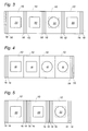
- the cover frame shown in Figure 1 comprises a cover plate, (hereinafter called "frame"), 10 which is essentially square and measures 85 mm by 85 mm in a particularly advantageous embodiment.
- the frame encloses an essentially square opening or notch 20, which may receive a switch key on a switch mounted in a mounting box or in a cable duct.
- the frame is intended to be mounted on the front of the completely mounted and electrically connected switch or outlet.
- a deep groove 12 is provided along both side edges, and as indicated by means of the dotted line 14, possibly two additional grooves make it easy for an electrician to remove one or two (or more, if necessary) of the outer edge portions 16, 18, (hereinafter called "bars").
- two cover frames 10 may be arranged adjacently about two boxes for mains switches and mains outlets mounted with a centre distance of 71 mm according to the CEE standard or with the centre distance of 57 mm used in some countries, such as France.
- Figure 2 illustrates a second embodiment in principle being essentially identical to the embodiment shown in Figure 1 except for the rounded corners.
- two grooves 12 are formed along the upper and lower edge and preferably spaced 14 mm therefrom, each said grooves defining a bar 16 intended to be separated (e.g. broken off) from the remaining cover frame.
- cover frame for instance two, three or four bars may be provided at each edge, said bar having a width of e.g. 3.5 mm, 7 and/or 14 mm.
- Figure 3 shows an example of an alignment of switches provided with switch keys 20 and plug outlets provided with outlet taps 22 having four frames 10 mounted so that the centre distance between two adjacent switches or outlets is 71 mm.
- four cover frames as shown in Figure 1 measuring 85 mm by 85 mm and a bar of 7 mm, a bar has to be broken off both frame sides, where a cover frame 10 adjoins another cover frame, as shown in Figure 3.
- a cover frame as shown in Figure 2 having a bar of 14 mm
- only one bar of the frame side adjacent another cover frame 19 is to be broken off.
- the frame shown in Figure 2 preferably has a square section 20, whereby it can be turned, as shown in Figure 1 and in Figure 2.
- the standard frame shown in Figure 1 may also be used as shown in Figure 5, in which three standard frames are mounted in alignment and no bars are broken off, i.e. having a centre distance of 85 mm.
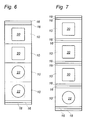
- FIGs 6 and 7 corresponding examples of four frames of the type shown in Figure 1 are arranged one above the other with a centre distance of 57 mm and 71 mm, respectively.
- the embodiments shown in Figures 2, 6, and 7 are preferably used for wiring in homes, while the embodiment shown in Figures 1, 3, 4, and 5 are intended for offices, in particular.
- the cover frame 10 as shown in Figures 1 and 2 is formed with a square section 20, the same frame may be used for mounting as shown in Figures 3, 4, and 5 as well as for vertical mounting as shown in Figures 6 and 7.
- the complete cover frame 10 with the bars is formed all in one piece, for instance by moulding or compression moulding. If desired, the moulding can be carried out in two steps with two different plastics materials to enable a subsequent separation of one or more bars.
- One or more grooves may be formed simultaneously during moulding, said grooves defining the line(s) of separation, and preferably being so deep that it is easy for the electrician to remove one or more bars, preferably without using any tools.
- tools to a small extent, such as a knife for separating the bars from the cover frame 10.
- Figure 8 and 9 are sectional views through examples of two typical embodiments of the cover frame.
- the grooves 12, 14 are merely indicated by means of thin, dotted lines.
- Figure 8 illustrates an example of an embodiment provided with a stepped bar.
- the upper face of the cover frame may have many different geometrical shapes. However, except for the grooves 12, 14, it is essentially plane, possibly slightly curved in horizontal and/or in vertical direction, when arranged on a vertical wall, or slightly pyramidal, and normally having an essentially smooth, matt or shiny surface being easy to keep clean.
- the groove may be shaped as a continuous, deep groove, and if desired, may be completely or partially filled with a filling material, such as a soft plastics which do not hinder the separation.
- the groove may also be composed of a line of perforations.
- the groove may be formed on the front, and completely filled, or covered by a trim strip. It is within the scope of the invention to form the groove on the back of the cover frame, whereby the front has a smooth surface regardless of the number of remaining bars.
- the groove may likewise be shaped in different ways, for instance V-shaped or with essentially vertical side and a horizontal or curved bottom.
- the grooves 12 are formed on the front as well as on the back of the standard frame. An enlarged section thereof being shown in Figure 10,.
- a comparatively small, aesthetically designed groove may be provided on the front, the depth thereof being such that said groove may cover any flashes after a bar has been broken off. A deeper groove may be provided on the back to ensure easy separation.
- cover frame and the bars are manufactured individually, whereafter the sections are assembled at the factory with suitable means, such as clip-on means intended therefor, by adhesion or by moulding in such a manner that a subsequent separation may be performed, when the cover frame is mounted on the site of application.
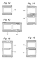
- Figure 11 shows yet another embodiment of the cover frame having a square opening 20, the cover plate with bar being rectangular (non-squared) and provided with grooves 12,13,14 along each side edge.
- the cover frame with the square opening can be turned 90°, the cover frame can be adapted to comply with several different demands as to the centre distances between adjacent switches and outlets by choosing suitable bar widths.
- Figure 12 shows an example of an embodiment provided with a stepped bar being 14 mm wide along the upper and lower edges of the cover frame, and a rectangular opening for a switch key.
- Figure 13 is an example of two cover frames of Figure 12 arranged side by side.
- Figures 14, 15, and 16 show examples of two cover frames arranged one above the other at a centre distance of 85 mm, 71 mm, and 57 mm, respectively.
- the invention may be varied in many ways with the scope of the attached claims.
- the number and width(s) of the bar(s) formed by means of grooves along one or more of the side edges for separation from the rest of the cover frame may be altered.
- the cover frame 10 may be rectangular as well as square and provided with a rectangular as well as a square opening 20.
Landscapes
- Engineering & Computer Science (AREA)
- Architecture (AREA)
- Civil Engineering (AREA)
- Structural Engineering (AREA)
- Connector Housings Or Holding Contact Members (AREA)
- Casings For Electric Apparatus (AREA)
- Switch Cases, Indication, And Locking (AREA)
Priority Applications (4)
| Application Number | Priority Date | Filing Date | Title |
|---|---|---|---|
| DK94610046T DK0706247T3 (da) | 1994-10-06 | 1994-10-06 | Modulsystem for dækrammer |
| EP94610046A EP0706247B1 (en) | 1994-10-06 | 1994-10-06 | A modular system for cover frames |
| DE69412097T DE69412097T2 (de) | 1994-10-06 | 1994-10-06 | Modulares System für Deckelrahmen |
| FI954736A FI114256B (fi) | 1994-10-06 | 1995-10-05 | Modulijärjestelmä peitekehyksiä varten |
Applications Claiming Priority (1)
| Application Number | Priority Date | Filing Date | Title |
|---|---|---|---|
| EP94610046A EP0706247B1 (en) | 1994-10-06 | 1994-10-06 | A modular system for cover frames |
Publications (2)
| Publication Number | Publication Date |
|---|---|
| EP0706247A1 EP0706247A1 (en) | 1996-04-10 |
| EP0706247B1 true EP0706247B1 (en) | 1998-07-29 |
Family
ID=8218185
Family Applications (1)
| Application Number | Title | Priority Date | Filing Date |
|---|---|---|---|
| EP94610046A Expired - Lifetime EP0706247B1 (en) | 1994-10-06 | 1994-10-06 | A modular system for cover frames |
Country Status (4)
| Country | Link |
|---|---|
| EP (1) | EP0706247B1 (da) |
| DE (1) | DE69412097T2 (da) |
| DK (1) | DK0706247T3 (da) |
| FI (1) | FI114256B (da) |
Families Citing this family (4)
| Publication number | Priority date | Publication date | Assignee | Title |
|---|---|---|---|---|
| EP1039608A1 (fr) * | 1999-03-26 | 2000-09-27 | Interlander Patermann, S.L. | Ensemble modulaire pour mécanismes électriques de surface et/ou à encastrer |
| DE10016592B4 (de) * | 2000-04-04 | 2005-04-28 | Berker Gmbh & Co Kg | Abdeckrahmen-System für elektrische Installationsgeräte |
| CZ11653U1 (cs) * | 2000-06-23 | 2001-11-01 | Abb Elektro Praga S.R.O. | Rámeček elektroinstalačního přístroje |
| GB2475480B (en) * | 2009-11-18 | 2012-08-22 | Eaton Electric Ltd | A plurality of sub-frame assemblies for assembling a modular frame and injection moulding apparatus for making injection moulded frames |
Family Cites Families (4)
| Publication number | Priority date | Publication date | Assignee | Title |
|---|---|---|---|---|
| DE1465268A1 (de) * | 1964-03-28 | 1969-02-06 | Berker Geb | Abdeckplatte,insbesondere Mehrfach-Abdeckplatte,fuer elektrische Installationsgeraete |
| DE2452173A1 (de) * | 1974-11-02 | 1976-05-06 | Giersiepen Eltech Ind | Mehrteiliger abdeckrahmen |
| DE3129061A1 (de) * | 1981-07-23 | 1983-02-03 | Gebrüder Merten GmbH & Co KG, 5270 Gummersbach | Elektrisches installationsgeraet |
| FR2640419A1 (fr) * | 1988-12-12 | 1990-06-15 | Burill Alain O | Plaque de proprete pour interrupteurs et prises electriques |
-
1994
- 1994-10-06 EP EP94610046A patent/EP0706247B1/en not_active Expired - Lifetime
- 1994-10-06 DK DK94610046T patent/DK0706247T3/da active
- 1994-10-06 DE DE69412097T patent/DE69412097T2/de not_active Expired - Lifetime
-
1995
- 1995-10-05 FI FI954736A patent/FI114256B/fi not_active IP Right Cessation
Also Published As
| Publication number | Publication date |
|---|---|
| DE69412097D1 (de) | 1998-09-03 |
| FI954736A0 (fi) | 1995-10-05 |
| EP0706247A1 (en) | 1996-04-10 |
| FI114256B (fi) | 2004-09-15 |
| DE69412097T2 (de) | 1999-04-01 |
| DK0706247T3 (da) | 1999-05-03 |
| FI954736L (fi) | 1996-04-07 |
Similar Documents
| Publication | Publication Date | Title |
|---|---|---|
| AU599769B2 (en) | Two-piece face plate for wall box mounted device | |
| US7262371B2 (en) | Modular raceway with base and integral divider | |
| US8093510B2 (en) | Downward facing receptacle assembly for cable raceway | |
| US5479747A (en) | Conduit connecting mechanism for a screen panel | |
| CA2305978A1 (en) | Device bracket | |
| GB2329533A (en) | Wire containment system for mounting on a wall | |
| CA1331773C (en) | Residential load centre assembly container | |
| US3864512A (en) | Cover for utility outlet | |
| US4931597A (en) | Junction boxes | |
| EP0706247B1 (en) | A modular system for cover frames | |
| US6215066B1 (en) | Outlet covering plate | |
| US3175031A (en) | Surface mounted electrical conduit and the like | |
| GB2214713A (en) | Electrical consumer units | |
| GB2289292A (en) | Skirting for running cables and for receiving electrical fittings | |
| CA2421472C (en) | Insulating unit for an electrical box | |
| JPH07106009B2 (ja) | 配線設備 | |
| EP0225725A2 (en) | Building blocks | |
| DE69607020T2 (de) | Kunststoffabzweigdose mit steckdosen | |
| EP2529383B1 (en) | Group of parts for the wall mounting of at least one modular electrical apparatus | |
| GB2266414A (en) | Trunking for electrical cables | |
| USRE27549E (en) | Single and dual service fittings | |
| EP1420494B1 (en) | Electric mechanism adapter for surface installations | |
| JP2750031B2 (ja) | フロアパネル用床コンセント装置 | |
| EP1091464B1 (en) | Accessory mounting for trunking | |
| GB2456087A (en) | Cable trunk system and mounting device. |
Legal Events
| Date | Code | Title | Description |
|---|---|---|---|
| PUAI | Public reference made under article 153(3) epc to a published international application that has entered the european phase |
Free format text: ORIGINAL CODE: 0009012 |
|
| AK | Designated contracting states |
Kind code of ref document: A1 Designated state(s): DE DK FR GB NL SE |
|
| 17P | Request for examination filed |
Effective date: 19960912 |
|
| 17Q | First examination report despatched |
Effective date: 19970305 |
|
| GRAG | Despatch of communication of intention to grant |
Free format text: ORIGINAL CODE: EPIDOS AGRA |
|
| GRAG | Despatch of communication of intention to grant |
Free format text: ORIGINAL CODE: EPIDOS AGRA |
|
| GRAH | Despatch of communication of intention to grant a patent |
Free format text: ORIGINAL CODE: EPIDOS IGRA |
|
| GRAH | Despatch of communication of intention to grant a patent |
Free format text: ORIGINAL CODE: EPIDOS IGRA |
|
| GRAA | (expected) grant |
Free format text: ORIGINAL CODE: 0009210 |
|
| AK | Designated contracting states |
Kind code of ref document: B1 Designated state(s): DE DK FR GB NL SE |
|
| REF | Corresponds to: |
Ref document number: 69412097 Country of ref document: DE Date of ref document: 19980903 |
|
| ET | Fr: translation filed | ||
| REG | Reference to a national code |
Ref country code: DK Ref legal event code: T3 |
|
| PLBE | No opposition filed within time limit |
Free format text: ORIGINAL CODE: 0009261 |
|
| STAA | Information on the status of an ep patent application or granted ep patent |
Free format text: STATUS: NO OPPOSITION FILED WITHIN TIME LIMIT |
|
| 26N | No opposition filed | ||
| REG | Reference to a national code |
Ref country code: GB Ref legal event code: IF02 |
|
| PGFP | Annual fee paid to national office [announced via postgrant information from national office to epo] |
Ref country code: NL Payment date: 20081005 Year of fee payment: 15 |
|
| PGFP | Annual fee paid to national office [announced via postgrant information from national office to epo] |
Ref country code: FR Payment date: 20081014 Year of fee payment: 15 |
|
| PGFP | Annual fee paid to national office [announced via postgrant information from national office to epo] |
Ref country code: GB Payment date: 20081001 Year of fee payment: 15 |
|
| REG | Reference to a national code |
Ref country code: NL Ref legal event code: V1 Effective date: 20100501 |
|
| REG | Reference to a national code |
Ref country code: FR Ref legal event code: ST Effective date: 20100630 |
|
| PG25 | Lapsed in a contracting state [announced via postgrant information from national office to epo] |
Ref country code: NL Free format text: LAPSE BECAUSE OF NON-PAYMENT OF DUE FEES Effective date: 20100501 Ref country code: FR Free format text: LAPSE BECAUSE OF NON-PAYMENT OF DUE FEES Effective date: 20091102 |
|
| PG25 | Lapsed in a contracting state [announced via postgrant information from national office to epo] |
Ref country code: GB Free format text: LAPSE BECAUSE OF NON-PAYMENT OF DUE FEES Effective date: 20091006 |
|
| PGFP | Annual fee paid to national office [announced via postgrant information from national office to epo] |
Ref country code: DK Payment date: 20121010 Year of fee payment: 19 |
|
| PGFP | Annual fee paid to national office [announced via postgrant information from national office to epo] |
Ref country code: DE Payment date: 20121003 Year of fee payment: 19 |
|
| PGFP | Annual fee paid to national office [announced via postgrant information from national office to epo] |
Ref country code: SE Payment date: 20121011 Year of fee payment: 19 |
|
| REG | Reference to a national code |
Ref country code: DK Ref legal event code: EBP Effective date: 20131031 |
|
| REG | Reference to a national code |
Ref country code: SE Ref legal event code: EUG |
|
| REG | Reference to a national code |
Ref country code: DE Ref legal event code: R119 Ref document number: 69412097 Country of ref document: DE Effective date: 20140501 |
|
| PG25 | Lapsed in a contracting state [announced via postgrant information from national office to epo] |
Ref country code: SE Free format text: LAPSE BECAUSE OF NON-PAYMENT OF DUE FEES Effective date: 20131007 Ref country code: DE Free format text: LAPSE BECAUSE OF NON-PAYMENT OF DUE FEES Effective date: 20140501 |
|
| PG25 | Lapsed in a contracting state [announced via postgrant information from national office to epo] |
Ref country code: DK Free format text: LAPSE BECAUSE OF NON-PAYMENT OF DUE FEES Effective date: 20131031 |