EP0706250B1 - Boítier d'encastrement pour appareillage électrique - Google Patents
Boítier d'encastrement pour appareillage électrique Download PDFInfo
- Publication number
- EP0706250B1 EP0706250B1 EP19950410096 EP95410096A EP0706250B1 EP 0706250 B1 EP0706250 B1 EP 0706250B1 EP 19950410096 EP19950410096 EP 19950410096 EP 95410096 A EP95410096 A EP 95410096A EP 0706250 B1 EP0706250 B1 EP 0706250B1
- Authority
- EP
- European Patent Office
- Prior art keywords
- case
- riders
- rider
- flange
- housing
- Prior art date
- Legal status (The legal status is an assumption and is not a legal conclusion. Google has not performed a legal analysis and makes no representation as to the accuracy of the status listed.)
- Expired - Lifetime
Links
Images

Classifications
-
- H—ELECTRICITY
- H02—GENERATION; CONVERSION OR DISTRIBUTION OF ELECTRIC POWER
- H02G—INSTALLATION OF ELECTRIC CABLES OR LINES, OR OF COMBINED OPTICAL AND ELECTRIC CABLES OR LINES
- H02G3/00—Installations of electric cables or lines or protective tubing therefor in or on buildings, equivalent structures or vehicles
- H02G3/02—Details
- H02G3/08—Distribution boxes; Connection or junction boxes
- H02G3/12—Distribution boxes; Connection or junction boxes for flush mounting
- H02G3/123—Distribution boxes; Connection or junction boxes for flush mounting in thin walls
Definitions
- the present invention relates to a housing for an electrical apparatus to be built into a support, especially in a thin or hollow wall, this housing comprising a body, means for retaining this body and means for clamping retaining means to ensure a firm mounting of the housing in said support, said retaining means comprising at at least two protruding jumpers mounted on the side wall of the housing, and movable along this wall, and said clamping means comprising at least two screws integral with the wall lateral and cooperating respectively with said riders to cause their displacement, said jumpers being made in one piece by injection molding with the body of the housing, by being linked to the body of the housing by at least one flange which can be sectioned, and constituting an area of least resistance allowing the detachment of these riders from the body of the housing, said body comprising recesses in which are initially housed the riders.
- housings of this type comprising two or more screws respectively carrying a retaining jumper made of synthetic material or metal and provided with an opening threaded in which the screw is engaged.
- a rotation in one direction of the screw causes the movement in one direction of the rider.
- a clockwise rotation of a watch causes the rider to move up or the front of the case and a rotation in opposite direction moves the jumper towards the bottom of the case.
- the jumpers are added elements which requires assembly and can be at the origin losses.
- Document FR-A-2616016 proposes to make the jumpers by molding with the body of the plastic case, but it is necessary to detach the jumpers from the wall of the box using a screwdriver.
- the present invention proposes to overcome these drawbacks by providing a housing of the type mentioned above designed to remove both assembly operations and risks loss of riders, while reducing its cost by simplifying its manufacturing.
- each niche is delimited upwards by a ramp which causes the rider to pivot at the start of his ascent caused by the screwing in the corresponding screw, at the same time as removing the flange for separate the rider from the body of the case, said ramp then moving the rider by one retracted position to a laterally deployed position.
- the housing 10 shown which corresponds to the prior art known comprises a housing body 11, preferably made by molding in material synthetic thermoplastic, two screws 12 housed in suitable cells 13 of the housing and two jumpers 14 which are mounted on the screws 12. These jumpers are attachments which can be made of synthetic material or metal. These riders have a plate 14a bent at one end to form a rim 14b and provided with an opening 14c internally threaded, in which the end of the screw 12 is engaged corresponding.
- the jumpers 14 are used to maintain the housing in a suitable housing provided in a support.
- This housing has a circular shape whose diameter corresponds to the diameter of the body of the housing.
- the support 15 shown in FIG. 3 is constituted by a panel, or a wall of hollow bricks or any other similar material.
- the jumpers are arranged near the bottom of the housing at at the time of placement or during storage. Keeping the case in place embedded in its support is effected by tightening the jumper 14 against the rear face of the support 15, as shown in Figure 3.
- the number of riders can of course be equal to two, three, four depending on the dimensions of the case or the quality of the support.
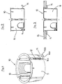
- the housing 20 as shown in Figures 4 to 7 comprises a body 21, substantially cylindrical, provided with a bottom 21a and side walls 21b. He is equipped of two diametrically opposed screws 22 and housed in cells 23 formed in the side wall of the housing. Each screw is associated with a jumper 24 which has the particularity to be molded in one piece with the body of the case. These jumpers have a part 24a in the form of a wafer and are originally linked to the lower part of the housing body by a flange 24b constituting a zone of least resistance which is brittle. This link is designed to tear off when the user turns the corresponding screw to raise the rider towards the opening of the case. To this end, the part 24a in the form of a plate has a threaded opening 24c for the passage of the corresponding screw.
- the part (24a) could equally well have a smooth cylindrical opening into which the screw (22) would be screwed; the net in the opening being in this case formed by the self-tapping screw.
- the jumpers are retracted from the side wall of the body of the housing and are housed in niches 25 in a waiting position. It is in this state that the user introduces the housing into a suitable housing provided in the support (not represented).
- the advantage of this embodiment lies in the fact that the manufacture of the body of the housing and jumpers are made during the same injection operation in a single mold.
- each jumper 24 is provided with a flat 28 in line with the flange 24b, said flat 28 allowing when sectioning the flange 24b to the part 27 to integrate into the volume of the jumper 24, to allow a rise without snag of the jumpers 24 along the alveoli 23.
- housing 11 may have a different shape, in particular square or rectangular.
- the number of screws 22 can be more than two depending on the size of the case.
Landscapes
- Engineering & Computer Science (AREA)
- Architecture (AREA)
- Civil Engineering (AREA)
- Structural Engineering (AREA)
- Casings For Electric Apparatus (AREA)
Description
- la figure 1 représente une vue en perspective d'un boítier selon l'art antérieur,
- la figure 2 représente une vue en élévation du boítier de la figure 1 en début de montage dans son support,
- la figure 3 représente une vue en élévation du boítier des figures précédentes en fin de montage dans son support,
- la figure 4 représente une vue de dessous du boítier selon l'invention,
- la figure 5 représente une vue partielle en coupe axiale du boítier de la figure 4,
- la figure 6 représente une vue partielle en coupe axiale du boítier de l'invention en début de montage sur son support, et
- la figure 7 représente une vue similaire à celle de la figure 6, en fin de montage du boítier sur son support.
Claims (4)
- Boítier pour un appareillage électrique à encastrer dans un support, notamment dans une paroi mince ou creuse, ledit boítier (20) comprenant un corps (21), des moyens de retenue de ce corps et des moyens de serrage des moyens de retenue pour assurer un montage ferme du boítier dans ledit support, lesdits moyens de retenue comprenant au moins deux cavaliers (24) protubérants montés sur la paroi latérale du boítier, et mobiles le long de cette paroi, et lesdits moyens de serrage comprenant au moins deux vis (22) solidaires de la paroi latérale et coopérant respectivement avec lesdits cavaliers pour engendrer leur déplacement, lesdits cavaliers (24) étant réalisés d'une pièce par un moulage par injection avec le corps du boítier (21), en étant liés au corps (21) du boítier (20) par au moins une bride (24b) pouvant être sectionnée, et constituant une zone de moindre résistance permettant le détachement de ces cavaliers du corps du boítier, ledit corps (21) comportant des niches (25) dans lesquelles sont initialement logés les cavaliers,
caractérisé en ce que
chaque niche est délimitée vers le haut par une rampe (26) qui provoque le pivotement du cavalier (24) au début de sa remontée occasionnée par le vissage de la vis (22) correspondante, en même temps que s'effectue l'arrachage de la bride (24b) pour désolidariser le cavalier du corps du boítier, ladite rampe déplaçant ensuite le cavalier (24) d'une position rétractée vers une position déployée latéralement. - Boítier selon la revendication 1, caractérisé en ce que les cavaliers (24) comportent une partie (24a) en forme de plaquette et ladite bride (24b) qui rattache la plaquette au corps du boítier.
- Boítier selon la revendication 2, caractérisé en ce que ladite partie (24a) comporte une ouverture (24c) filetée pour le passage de la vis correspondante.
- Boítier selon la revendication 2, caractérisé en ce que chaque cavalier (24) est pourvu d'un méplat (28) au droit de la bride (24b), ledit méplat (28) permettant lors du sectionnement de la bride (24b) à la partie résiduelle (27) de s'intégrer dans le volume du cavalier (24), pour autoriser une remontée sans accroc des cavaliers (24) le long des alvéoles (23).
Applications Claiming Priority (2)
| Application Number | Priority Date | Filing Date | Title |
|---|---|---|---|
| FR9412037A FR2725318B1 (fr) | 1994-10-04 | 1994-10-04 | Boitier d'encastrement pour appareillage electrique |
| FR9412037 | 1994-10-04 |
Publications (2)
| Publication Number | Publication Date |
|---|---|
| EP0706250A1 EP0706250A1 (fr) | 1996-04-10 |
| EP0706250B1 true EP0706250B1 (fr) | 1998-12-09 |
Family
ID=9467692
Family Applications (1)
| Application Number | Title | Priority Date | Filing Date |
|---|---|---|---|
| EP19950410096 Expired - Lifetime EP0706250B1 (fr) | 1994-10-04 | 1995-09-05 | Boítier d'encastrement pour appareillage électrique |
Country Status (4)
| Country | Link |
|---|---|
| EP (1) | EP0706250B1 (fr) |
| DE (1) | DE69506509T2 (fr) |
| ES (1) | ES2126854T3 (fr) |
| FR (1) | FR2725318B1 (fr) |
Families Citing this family (7)
| Publication number | Priority date | Publication date | Assignee | Title |
|---|---|---|---|---|
| FR2772202B1 (fr) * | 1997-12-10 | 2000-02-18 | Legrand Sa | Accessoire de fixation a griffe, notamment pour boite d'encastrement, et boite d'encastrement correspondante |
| FR2781097B1 (fr) * | 1998-07-08 | 2000-10-13 | Legrand Sa | Boite d'encastrement pour cloison seche a patte(s) de serrage initialement d'un seul tenant, notamment pour appareillage electrique |
| DE19922212C2 (de) * | 1999-05-14 | 2003-09-25 | Bernd Sperber | Einbaudose für Elektroinstallation |
| FR2885745B1 (fr) * | 2005-05-10 | 2007-08-10 | Legrand France | Boite d'encastrement et procede de fabrication |
| DE102009026515A1 (de) * | 2009-05-27 | 2010-12-02 | Hoff, Alwin, Dipl.-Ing. (FH) | Modulare Einbaudose |
| EP3059821A1 (fr) * | 2015-02-20 | 2016-08-24 | ABB Oy | Boîtier de montage et procédé de fabrication de boîtier de montage |
| US11088518B2 (en) | 2017-10-06 | 2021-08-10 | Lutron Technology Company Llc | Mounting mechanism for an electrical device |
Family Cites Families (2)
| Publication number | Priority date | Publication date | Assignee | Title |
|---|---|---|---|---|
| DE3717443A1 (de) * | 1987-05-23 | 1988-12-01 | Wiska Hoppmann & Mulsow Gmbh & | Elektro-hohlwanddose |
| DE9311023U1 (de) * | 1993-07-23 | 1993-12-23 | Eichsfelder Technik eitech GmbH, 37308 Pfaffschwende | Einbaudose für elektrische Schalter oder Verteilerstellen |
-
1994
- 1994-10-04 FR FR9412037A patent/FR2725318B1/fr not_active Expired - Fee Related
-
1995
- 1995-09-05 EP EP19950410096 patent/EP0706250B1/fr not_active Expired - Lifetime
- 1995-09-05 ES ES95410096T patent/ES2126854T3/es not_active Expired - Lifetime
- 1995-09-05 DE DE1995606509 patent/DE69506509T2/de not_active Expired - Fee Related
Also Published As
| Publication number | Publication date |
|---|---|
| FR2725318B1 (fr) | 1996-10-31 |
| DE69506509D1 (de) | 1999-01-21 |
| ES2126854T3 (es) | 1999-04-01 |
| FR2725318A1 (fr) | 1996-04-05 |
| DE69506509T2 (de) | 1999-06-10 |
| EP0706250A1 (fr) | 1996-04-10 |
Similar Documents
| Publication | Publication Date | Title |
|---|---|---|
| EP3310690B1 (fr) | Procédé pour fabriquer une valve d'aérosol et valve d'aérosol | |
| FR2904269A1 (fr) | Tubulure de remplissage du seservoir de carburant d'un vehicule automobile. | |
| EP2143846B1 (fr) | Dispositif d'encastrement pour éléments sanitaires | |
| EP1849697A1 (fr) | Boîtier et ensemble prêts à monter pour motocyclette, motocyclette correspondante et son procédé de fabrication | |
| EP1722453B1 (fr) | Boîte d'encastrement | |
| EP0706250A1 (fr) | Boîtier d'encastrement pour appareillage électrique | |
| WO2005035336A1 (fr) | Obturateur pour partie creuse de vehicule automobile | |
| FR2689331A1 (fr) | Embout à rapporter sur une paroi pour y constituer une sortie de câble. | |
| EP1093839B1 (fr) | Boítier de filtre à couvercle vissable encliquetable | |
| EP1468147A1 (fr) | Tuyau de douche ayant une vanne a deux voies, et vanne a deux voies pour un tuyau de douche | |
| EP0918612B1 (fr) | Dispositif de marquage pour moule | |
| EP1444051B1 (fr) | Distributeur de produit fluide | |
| EP3106587A1 (fr) | Dispositif de fixation d'un objet immergé dans un bassin subaquatique | |
| FR2610761A1 (fr) | Organe de commande d'un dispositif tel qu'un interrupteur electrique, du type en forme d'un levier pivotant | |
| FR2689940A3 (fr) | Ecrou à enfoncer en matière plastique. | |
| EP1205672A1 (fr) | Support de retenue souple d'un objet sur une cloison | |
| EP1164676A1 (fr) | Dispositif de montage d'un appareil électrique sur un conduit de câblage | |
| FR2791114A1 (fr) | Dispositif permettant de commander l'ecoulement d'un fluide et l'orientation de cet ecoulement | |
| EP1147834B1 (fr) | Emporte-pièces | |
| FR3116011A1 (fr) | Diffuseur pour générateur d’aérosol | |
| EP1158634A2 (fr) | Embout pour goulotte de cheminement de câbles ou de conducteurs électriques | |
| EP1466818A2 (fr) | Procédé de fabrication d'une pièce de carrosserie de véhicule automobile, destinée à être peinte de la même couleur que la carrosserie du véhicule | |
| EP1251601A1 (fr) | Dispositif de blindage électromagnétique pour connecteur électrique | |
| EP0572296B1 (fr) | Système de scellement chimique d'un élément de fixation dans un matériau creux | |
| EP2316628B1 (fr) | Pièce moulée comportant une paroi présentant un trou destiné a recevoir un pilote |
Legal Events
| Date | Code | Title | Description |
|---|---|---|---|
| PUAI | Public reference made under article 153(3) epc to a published international application that has entered the european phase |
Free format text: ORIGINAL CODE: 0009012 |
|
| AK | Designated contracting states |
Kind code of ref document: A1 Designated state(s): BE DE ES GB IT |
|
| 17P | Request for examination filed |
Effective date: 19960924 |
|
| 17Q | First examination report despatched |
Effective date: 19971023 |
|
| GRAG | Despatch of communication of intention to grant |
Free format text: ORIGINAL CODE: EPIDOS AGRA |
|
| GRAG | Despatch of communication of intention to grant |
Free format text: ORIGINAL CODE: EPIDOS AGRA |
|
| GRAH | Despatch of communication of intention to grant a patent |
Free format text: ORIGINAL CODE: EPIDOS IGRA |
|
| GRAH | Despatch of communication of intention to grant a patent |
Free format text: ORIGINAL CODE: EPIDOS IGRA |
|
| GRAA | (expected) grant |
Free format text: ORIGINAL CODE: 0009210 |
|
| AK | Designated contracting states |
Kind code of ref document: B1 Designated state(s): BE DE ES GB IT |
|
| PG25 | Lapsed in a contracting state [announced via postgrant information from national office to epo] |
Ref country code: GB Free format text: LAPSE BECAUSE OF NON-PAYMENT OF DUE FEES Effective date: 19981209 |
|
| REF | Corresponds to: |
Ref document number: 69506509 Country of ref document: DE Date of ref document: 19990121 |
|
| ITF | It: translation for a ep patent filed | ||
| REG | Reference to a national code |
Ref country code: ES Ref legal event code: FG2A Ref document number: 2126854 Country of ref document: ES Kind code of ref document: T3 |
|
| GBV | Gb: ep patent (uk) treated as always having been void in accordance with gb section 77(7)/1977 [no translation filed] |
Effective date: 19981209 |
|
| PG25 | Lapsed in a contracting state [announced via postgrant information from national office to epo] |
Ref country code: BE Free format text: LAPSE BECAUSE OF NON-PAYMENT OF DUE FEES Effective date: 19990930 |
|
| PLBE | No opposition filed within time limit |
Free format text: ORIGINAL CODE: 0009261 |
|
| STAA | Information on the status of an ep patent application or granted ep patent |
Free format text: STATUS: NO OPPOSITION FILED WITHIN TIME LIMIT |
|
| 26N | No opposition filed | ||
| BERE | Be: lapsed |
Owner name: S.A. SCHNEIDER ELECTRIC Effective date: 19990930 |
|
| PGFP | Annual fee paid to national office [announced via postgrant information from national office to epo] |
Ref country code: IT Payment date: 20080926 Year of fee payment: 14 |
|
| PGFP | Annual fee paid to national office [announced via postgrant information from national office to epo] |
Ref country code: DE Payment date: 20080908 Year of fee payment: 14 |
|
| PGFP | Annual fee paid to national office [announced via postgrant information from national office to epo] |
Ref country code: ES Payment date: 20081021 Year of fee payment: 14 |
|
| PG25 | Lapsed in a contracting state [announced via postgrant information from national office to epo] |
Ref country code: DE Free format text: LAPSE BECAUSE OF NON-PAYMENT OF DUE FEES Effective date: 20100401 |
|
| PG25 | Lapsed in a contracting state [announced via postgrant information from national office to epo] |
Ref country code: IT Free format text: LAPSE BECAUSE OF NON-PAYMENT OF DUE FEES Effective date: 20090905 |
|
| REG | Reference to a national code |
Ref country code: ES Ref legal event code: FD2A Effective date: 20110715 |
|
| PG25 | Lapsed in a contracting state [announced via postgrant information from national office to epo] |
Ref country code: ES Free format text: LAPSE BECAUSE OF NON-PAYMENT OF DUE FEES Effective date: 20110705 |
|
| PG25 | Lapsed in a contracting state [announced via postgrant information from national office to epo] |
Ref country code: ES Free format text: LAPSE BECAUSE OF NON-PAYMENT OF DUE FEES Effective date: 20090906 |