EP0706301A2 - Générateur de son de taille réduite - Google Patents
Générateur de son de taille réduite Download PDFInfo
- Publication number
- EP0706301A2 EP0706301A2 EP95306859A EP95306859A EP0706301A2 EP 0706301 A2 EP0706301 A2 EP 0706301A2 EP 95306859 A EP95306859 A EP 95306859A EP 95306859 A EP95306859 A EP 95306859A EP 0706301 A2 EP0706301 A2 EP 0706301A2
- Authority
- EP
- European Patent Office
- Prior art keywords
- housing
- small
- sound generator
- terminals
- sized sound
- Prior art date
- Legal status (The legal status is an assumption and is not a legal conclusion. Google has not performed a legal analysis and makes no representation as to the accuracy of the status listed.)
- Withdrawn
Links
Images





Classifications
-
- H—ELECTRICITY
- H04—ELECTRIC COMMUNICATION TECHNIQUE
- H04R—LOUDSPEAKERS, MICROPHONES, GRAMOPHONE PICK-UPS OR LIKE ACOUSTIC ELECTROMECHANICAL TRANSDUCERS; ELECTRIC HEARING AIDS; PUBLIC ADDRESS SYSTEMS
- H04R13/00—Transducers having an acoustic diaphragm of magnetisable material directly co-acting with electromagnet
- H04R13/02—Telephone receivers
-
- H—ELECTRICITY
- H04—ELECTRIC COMMUNICATION TECHNIQUE
- H04R—LOUDSPEAKERS, MICROPHONES, GRAMOPHONE PICK-UPS OR LIKE ACOUSTIC ELECTROMECHANICAL TRANSDUCERS; ELECTRIC HEARING AIDS; PUBLIC ADDRESS SYSTEMS
- H04R1/00—Details of transducers, loudspeakers or microphones
- H04R1/06—Arranging circuit leads; Relieving strain on circuit leads
-
- H—ELECTRICITY
- H05—ELECTRIC TECHNIQUES NOT OTHERWISE PROVIDED FOR
- H05K—PRINTED CIRCUITS; CASINGS OR CONSTRUCTIONAL DETAILS OF ELECTRIC APPARATUS; MANUFACTURE OF ASSEMBLAGES OF ELECTRICAL COMPONENTS
- H05K1/00—Printed circuits
- H05K1/02—Details
- H05K1/0284—Details of three-dimensional rigid printed circuit boards
-
- H—ELECTRICITY
- H05—ELECTRIC TECHNIQUES NOT OTHERWISE PROVIDED FOR
- H05K—PRINTED CIRCUITS; CASINGS OR CONSTRUCTIONAL DETAILS OF ELECTRIC APPARATUS; MANUFACTURE OF ASSEMBLAGES OF ELECTRICAL COMPONENTS
- H05K1/00—Printed circuits
- H05K1/02—Details
- H05K1/14—Structural association of two or more printed circuits
- H05K1/141—One or more single auxiliary printed circuits mounted on a main printed circuit, e.g. modules, adapters
-
- H—ELECTRICITY
- H05—ELECTRIC TECHNIQUES NOT OTHERWISE PROVIDED FOR
- H05K—PRINTED CIRCUITS; CASINGS OR CONSTRUCTIONAL DETAILS OF ELECTRIC APPARATUS; MANUFACTURE OF ASSEMBLAGES OF ELECTRICAL COMPONENTS
- H05K3/00—Apparatus or processes for manufacturing printed circuits
- H05K3/30—Assembling printed circuits with electric components, e.g. with resistors
- H05K3/32—Assembling printed circuits with electric components, e.g. with resistors electrically connecting electric components or wires to printed circuits
- H05K3/34—Assembling printed circuits with electric components, e.g. with resistors electrically connecting electric components or wires to printed circuits by soldering
- H05K3/341—Surface mounted components
- H05K3/3431—Leadless components
- H05K3/3442—Leadless components having edge contacts, e.g. leadless chip capacitors, chip carriers
Definitions
- the present invention relates to a sound/oscillation generator to be used as a notification means in a portable telephone or the like, namely, to a small-sized sound generator for generating sound and oscillation.
- a small-sized sound generator has been used as a notification means in small-sized electronic equipments such as a portable telephone, a pager unit and its form is illustrated in Figs. 7 to 11.
- the small-sized sound generator shown in Fig. 7 is a standard electroacoustic transducer comprising a housing 200 composed of an upper housing 202 and a lower housing 204 which are integrated with each other to form in a cylindrical shape, an electroacoustic transducer portion 206 housed in the housing 200, and lead terminals 208 and 210 respectively formed in a rod shape and disposed at a back side of the housing 200.
- through holes 214 and 216 are formed on a circuit board 212, and the lead terminals 208 and 210 penetrate the through holes 214 and 216 and they are electrically connected to a conductive pattern 218 formed on the back side of the circuit board 212 by way of soldering.
- a sound emitting hole 219 formed in the upper housing 202 crosses at right angles to the circuit board 212, namely, it is directed upward.
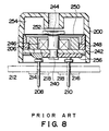
- the small-sized sound generator shown in Fig. 8 is different from that shown in Fig. 7 in respect that the housing 200 of former consists of a single housing but that in Fig. 7 consists of the integrated upper and lower housings. Other elements in Fig. 8 are the same as those in Fig. 7.
- the small-sized sound generator shown in Figs. 9A and 9B includes a fixing projection 220 formed at a side surface portion of the housing 200, and the lead terminals 208 and 210 formed at a board 256, which closes the back side of the housing 200, and positioned at both sides of the fixing projection 220, wherein each of the lead terminals 208 and 210 is made of a plate-shaped material bent in an L shape forming a flat portion 222 in a projecting direction of the fixing projection 220.
- the fixing projection 220 is inserted into a through hole 224 or a recess formed on the circuit board 212 so as to fix the housing 200 on the circuit board 212, and the flat portions 222 of the lead terminals 208 and 210 are electrically connected to a circuit conductor 226 on the circuit board 212 by soldering, etc.
- the sound emitting hole 219 formed in the housing 200 is directed in parallel with the circuit board 212.
- the small-sized sound generator shown in Fig. 10 has the same housing 200 and the internal structure thereof as those of Fig. 8.
- the lead terminals 208 and 210 made of the plate-shaped material like those of Fig. 9 extend from the wall surface side of the housing 200 to the opposite side on which the sound emitting hole 219 is formed, where they are bent in an L shape to form flat portions 228.
- a through hole 230 is formed on the circuit board 212, and the sound emitting hole 219 is aligned with the through hole 230 so as to set the housing 200 on the circuit board 212.
- the flat portions 228 of the lead terminals 208 and 210 and the conductive pattern on the circuit board 212 are soldered to each other.
- This small-sized sound generator is characterized in that the configurations of the lead terminals 208 and 210 are modified so as to emit sound through the circuit board 212.
- the small-sized sound generator shown in Figs. 11A and 11B includes a housing 200 of flat rectangular parallelepiped having each side of several millimeters, and the electroacoustic transducer portion 206 housed in the housing 200, wherein a positive lead terminal 208 and a dummy terminal 209 are provided at one side surface of a long side of the housing 200, and a negative lead terminal 210 and a dummy terminal 211 are provided at the other side surface of the long side of the housing 200.
- Each of the lead terminals 208 and 210 is provided for surface mounting and each of the dummy terminals 209 and 211 is for fixing purpose.
- the housing 200 comprises the upper housing 202 of rectangular parallelepiped and a plate-shaped lower housing 204 which are integrated with each other, wherein a pair of positioning projections 232 are formed at the back side of the lower housing 204.
- the positioning projections 232 are inserted into positioning through holes 234 formed on the circuit board 212 so as to position the housing 200, while the lead terminals 208 and 210 and the dummy terminals 209 and 211 are soldered to the conductive pattern on the circuit board 212 so as to electrically connect these terminals to the conductive pattern.
- the electroacoustic transducer portion 206 is housed in the housing 200, wherein the electroacoustic transducer portion 206 comprises a base 242 comprising a pole piece 240, a core 244 provided upright on the base 242, and a coil 246 wound around the core 244, and an annular magnet 248 is disposed around a peripheral surface of the coil 246.
- a diaphragm 250 made of a magnetic material is disposed on an inner wall portion of the housing 200, wherein magnetic force of the annular magnet 248 acts upon the diaphragm 250 and also acts upon the core 244 through the base 242 so as to form a closed magnetic path through a gap 252.
- the coil 246 is energized by an ac signal applied to the lead terminals 208 and 210 and is magnetized by an alternating magnetic field in response to an electric signal to be applied to the core 244.
- the diaphragm 250 is oscillated by the alternating magnetic field so as to permit a resonant chamber 254 to resonate so that the oscillation or sound is emitted from the sound emitting hole 219 while the oscillating energy is effectively emitted toward an opening direction thereof.
- the mounting form of the small-sized sound generator namely, the directivity of the sound emitting hole 219 is important in the electronic equipments.
- the lead terminals 208 and 210 per se are changed or the shapes of the lead terminals 208 and 210 are changed to cope with various mounting forms.
- the shape of the small-sized sound generator is complex by such a partial change of the shapes of the lead terminals 208 and 210.
- the lead terminals 208 and 210 are individual parts in assembling thereof, there cause such problems that the number of parts increase, the small-sized sound generator are being prevented from being miniaturized, and assembling steps increase.
- the present invention provides a small-sized sound generator capable of simplifying structures of terminals, facilitating surface mounting, and setting a direction of the sound emitting hole to an arbitrary direction.
- a small-sized sound generator (52A, 52B, 52C, 52D) according to a first aspect of the invention, is characterized in comprising a housing (2), a converting means (electroacoustic transducer portion 18) housed in the housing (2) for converting an electric signal into sound or oscillation, and conductors disposed on surfaces of the housing (2), each conductor having an arbitrary pattern so as to form terminals (10, 12) integrally formed with the housing.
- the small-sized sound generator when the conductors each having an arbitrary pattern are disposed on the surfaces of the housing so that the terminals are integrally formed with the housing. That is, the housing per se constitutes a part of the terminals wherein lead terminals as assembling parts are not present like the prior art small-sized sound generator. The number of parts are reduced by the number of lead terminals so that the terminal structure can be simplified to thereby miniaturize the small-sized sound generator.
- the small-sized sound generator is connected to the circuit board, terminals of the housing are brought into contact with the conductive pattern on the circuit board and the former is electrically connected to the latter by a connecting means such as soldering.
- a small-sized sound generator is characterized in that the housing (2) has a shape of polyhedron and conductors each having an arbitrary pattern are disposed on the surface of the housing (2) for forming terminals integrally with the housing (2).
- each surface of the housing constituting the polyhedron becomes a connecting surface, i. e., a mounting surface on the circuit board.
- the terminals on the housing can be connected to the circuit board with the specific surface directed to an arbitrary direction, so that the sound emitting hole having directional can be directed to the arbitrary direction.
- Terminals can be formed on the surfaces of the housing on which the sound emitting hole is formed, and the terminals are connected to the circuit board, whereby the sound emitting hole can be directed to the circuit board so that the sound can be emitted so as to penetrate the circuit board.
- the small-sized sound generator according to a second aspect of the invention is characterized in that projections (44, 46, 48, 50) are formed on a part of the housing (2) and the conductors are disposed on the projections to form terminals.
- the projections are formed on the part of the housing, the conductors are disposed on the projections to form the terminals, which can cope with a connecting form other than the surface mounting.
- the projections can be utilized as temporarily fixing means to the circuit board, etc., or positioning means.
- the other terminals serve as the electric connection
- the positioning and fixing by the projections, and soldering of the terminals, etc. render the connection and fixing firm, which contributes to the reliability of the circuit connection.
- the shapes of the projections may be either columnar or plate-shaped. If the plate-shaped projections are formed so as to extend a part of the housing, the housing can be electrically connected to the circuit board, and the projections can be fixed to the circuit board by fixing means such as a screw so that the fixing can be more stabilized.
- the terminals may be formed on the surface of the housing made of synthetic resin. Accordingly, a metallic plate having an arbitrary pattern may be applied to on or embedded in the surfaces of the housing to form the terminals, conductive layers (substrate plating layer 105, protecting plating layer 107, finished plating layer 109) may be formed by plating, or the conductive layers may be formed by printing, etc.
- the terminals can be easily formed by various methods, e.g., embedding a metallic plate in, or plating the metallic layer on or printing the metallic layer on the housing made of synthetic resin.
- the most proper method can be selected from the aforementioned methods depending on the shape of the housing, i. e., concave, cornered, plane surface, etc. so that yield and reliability can be enhanced.
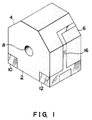
- Figs. 1, 2 and 3 show a small-sized sound generator according to a first embodiment of the present invention.
- a housing 2 made of insulating synthetic resin for forming a shape of polyhedron, wherein the housing 2 is formed of an octahedron having surfaces 4 and 6 on a rectangular parallelepiped.
- the housing 2 is opened at the back side thereof and has a circular sound emitting hole 8 at the front side thereof.
- a pair of terminals 10 and 12 are integrally formed with the housing 2 by conductors each forming a continuous pattern on a front surface, left and right surfaces, a rear surface and a bottom surface of the housing 2.
- the terminals 10 and 12 form surface mounting terminals for permitting each surface of the housing 2 to serve as a connecting surface, i. e., a mounting surface.
- each pattern is not necessary to be conformed to each other. The reason why each of the terminals 10 and 12 is partially rectangular to occupy a large area is for convenience of connections thereof.
- L-shaped extension terminal portions 14 and 16 are formed at the side surface portions of the housing 2, wherein the terminals 10 and 12 at the side surface portions and each of the terminals 10 and 12 formed at the rear surface portion are electrically connected with each other through the extension terminal portions 14 and 16.
- These terminals 10 and 12 and the extension terminal portions 14 and 16 are formed, for example, by forming protection plating layer on the surfaces of conductive layers made of copper, etc.
- Fig. 4 is a cross-sectional view taken along lines IV-IV of Fig. 2 in which the terminal 10 comprises a conductor forming portion 101 formed on the surface of the housing 2, a catalyst layer 103, a substrate plating layer 105 comprising copper, etc., a protection plating layer 107 such as a nickel plating layer, etc., a finishing plating layer 109 such as a metallic layer, etc. That is, the substrate plating layer 105, the protection plating layer 107 and the finishing plating layer 109 are respectively formed as a conductive layer, and the terminal 12 is structured in the same manner as the terminal 10.
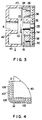
- An electroacoustic transducer portion 18 is housed in the housing 2 as a converting means for converting an electric signal into sound or oscillation as shown in Fig. 3. That is, a diaphragm 20 is disposed inside the housing 2 as the converting means for converting magnetic oscillation into a mechanical oscillation.
- the diaphragm 20 is formed of a thin plate made of magnetic material and has a magnetic piece 22 fixed to the center thereof as a means for substantially increasing mass.
- the diaphragm 20 is supported by a concave portion 24 formed inside the housing 2 and a top portion of a supporting ring 26 as a supporting means disposed in the housing 2 while edge portions of the diaphragm 20 is clumped between the concave portion 24 and the top portion of the supporting ring 26.
- a pole piece 28 is disposed in the housing 2, and it includes a columnar core 32 which is provided upright on the center of a discoidal base 30, wherein a gap 33 is defined between the core 32 and the diaphragm 20.
- the base 30 and the core 32 are respectively made of magnetic materials.
- the base 30 is fixed to the housing 2, and a central axis of the core 32 conforms to the center of the diaphragm 20.
- a cylindrical coil 34 is wound around the core 32, and distal ends of the coil 34 are connected to the terminals 10 and 12.
- An annular magnet 38 is disposed around the peripheral surface of the coil 34 with a gap 36 being defined therebetween.
- the annular magnet 38 is positioned by an inner diameter portion of the supporting ring 26.
- the annular magnet 38, the pole piece 28 and the diaphragm 20 form a closed magnetic path, wherein magnetic force of the annular magnet 38 functions as attraction of the diaphragm 20 serving as a biased magnetic field.
- a resonant space 40 is defined at the upper side of the diaphragm 20, and a sound emitting cylinder 42 having the sound emitting hole 8 is formed for opening the resonant space 40 to the atmosphere.
- the core 32 and the base 30 are magnetized by the alternating magnetic field which is generated by the coil 34, so that the alternating magnetic field oscillates the diaphragm 20 vertically through the closed magnetic path.
- the oscillation depends on the frequency of the ac input signal, which results in resonating the resonant space 40.
- the resonating oscillation and the resonating sound oscillate the housing 2 and are emitted to the atmosphere through the sound emitting hole 8.
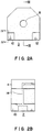
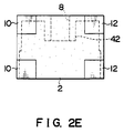
- Figs. 5A to 5D show a small-sized sound generator according to the second embodiment of the present invention.
- the small-sized sound generator comprises projections 44 and 46 serving as terminal pins on the terminals 10 and 12 of the bottom surface of the housing 2, and projections 48 and 50 serving as terminal pins on the terminal 10 and 12 of the rear surface of the housing 2.
- Each of the projections 44, 46, 48, 50 is columnar, wherein the projections 44 and 46 are disposed diagonally on the bottom surface.
- Four projections 44 and 46 may be disposed diagonally on the bottom surface.
- These projections 44, 46 and 48, 50 constitute a part of the terminals 10 and 12 by providing conductors on the surfaces thereof.
- An internal structure of the small-sized sound generator of the second embodiment is the same as that of the first embodiment.
- terminals 10 and 12 are formed in each surface of the housing 2, various mounting forms can be taken as shown in Fig. 6.
- Denoted at 52A, 52B and 52C show the small-sized sound generator of the first embodiment and 52D shows the small-sized sound generator of the second embodiment.
- circuit conductors 56 and 58 are formed diagonally on a circuit board 54 wherein the terminals 10 and 12 on the bottom surface of the housing 2 are soldered to the circuit conductors 56 and 58.
- the sound emitting hole 8 of the small-sized sound generator 52A is directed in parallel with the circuit board 54.
- circuit conductors 60 and 62 are disposed in parallel with each other on the circuit board 54 wherein the terminals 10 and 12 on the rear surface of the housing 2 are soldered to the circuit conductors 60 and 62. As a result, the sound emitting hole 8 of the small-sized sound generator 52B is directed upward.
- circuit conductors 64 and 66 are disposed in parallel with each other on the circuit board 54 wherein the terminals 10 and 12 on the front surface of the housing 2 are soldered to the circuit conductors 64 and 66.
- the circuit board 54 has, e. g., a rectangular opening 68 corresponding to the sound emitting hole 8, wherein sound is emitted from the sound emitting hole 8 through the rectangular opening 68 of the circuit board 54.
- the projections 44 and 46 forming a part of the terminals 10 and 12 penetrate the through hole formed on the circuit board 54, wherein the projections 44 and 46 and each of circuit conductors 70 and 72 are individually soldered to each other.
- the projections 44 and 46 are inserted into and temporarily fixed to the circuit board 54 so as to serve as a fixing means.
- the small-sized sound generator 52D can be mounted on the back side of the circuit board 54 like the small-sized sound generator 52A.
- the terminals 10 and 12 can be formed by a conductor forming process such as a conductor printing or spattering.
- the terminals 10 and 12 may be formed by applying or embedding a metallic plate such as a metallic film with its metal surface exposed to or in the housing 2.
- the present invention is not limited to the aforementioned first and second embodiments but includes various modifications and applications to achieve the object of the present invention.
Landscapes
- Physics & Mathematics (AREA)
- Electromagnetism (AREA)
- Engineering & Computer Science (AREA)
- Acoustics & Sound (AREA)
- Signal Processing (AREA)
- Electrostatic, Electromagnetic, Magneto- Strictive, And Variable-Resistance Transducers (AREA)
- Telephone Set Structure (AREA)
- Audible-Bandwidth Dynamoelectric Transducers Other Than Pickups (AREA)
- Details Of Audible-Bandwidth Transducers (AREA)
Applications Claiming Priority (2)
| Application Number | Priority Date | Filing Date | Title |
|---|---|---|---|
| JP264515/94 | 1994-10-03 | ||
| JP6264515A JP2862802B2 (ja) | 1994-10-03 | 1994-10-03 | 小型発音体 |
Publications (2)
| Publication Number | Publication Date |
|---|---|
| EP0706301A2 true EP0706301A2 (fr) | 1996-04-10 |
| EP0706301A3 EP0706301A3 (fr) | 1999-05-19 |
Family
ID=17404323
Family Applications (1)
| Application Number | Title | Priority Date | Filing Date |
|---|---|---|---|
| EP95306859A Withdrawn EP0706301A3 (fr) | 1994-10-03 | 1995-09-28 | Générateur de son de taille réduite |
Country Status (5)
| Country | Link |
|---|---|
| US (1) | US5721785A (fr) |
| EP (1) | EP0706301A3 (fr) |
| JP (1) | JP2862802B2 (fr) |
| CN (1) | CN1080530C (fr) |
| FI (1) | FI954673A7 (fr) |
Cited By (2)
| Publication number | Priority date | Publication date | Assignee | Title |
|---|---|---|---|---|
| WO2000027166A3 (fr) * | 1998-11-02 | 2000-10-26 | Sarnoff Corp | Conception de transducteurs pour protheses auditives et autres dispositifs |
| EP1699258A1 (fr) * | 2005-03-02 | 2006-09-06 | Hosiden Corporation | Transducteur électro-acoustique avec support |
Families Citing this family (6)
| Publication number | Priority date | Publication date | Assignee | Title |
|---|---|---|---|---|
| JP3262982B2 (ja) * | 1996-02-07 | 2002-03-04 | スター精密株式会社 | 電気音響変換器 |
| JP3532715B2 (ja) * | 1996-11-20 | 2004-05-31 | スター精密株式会社 | 電磁音響変換器 |
| EP1096650B1 (fr) * | 1998-07-06 | 2006-11-22 | Sanyo Electric Co., Ltd. | Generateur de sons/vibrations |
| US6229903B1 (en) * | 1999-06-14 | 2001-05-08 | Citizen Electronics Co., Ltd. | Mounting structure for electromagnetic sound generator |
| KR101417783B1 (ko) * | 2007-09-18 | 2014-07-11 | 삼성전자 주식회사 | 전자기기용 케이스 |
| JP5458696B2 (ja) * | 2009-06-29 | 2014-04-02 | コニカミノルタ株式会社 | 太陽光発電システム及びそれを構成する太陽光発電セル、コントローラ、ユーザ端末 |
Family Cites Families (9)
| Publication number | Priority date | Publication date | Assignee | Title |
|---|---|---|---|---|
| JPS6113394A (ja) * | 1984-06-28 | 1986-01-21 | 松下冷機株式会社 | 氷入り飲料の自動販売機 |
| JPS6113395A (ja) * | 1984-06-29 | 1986-01-21 | 日本自動販売株式会社 | 飲料自動販売機 |
| JPH021797U (fr) * | 1988-06-16 | 1990-01-08 | ||
| JP2575831B2 (ja) * | 1988-07-25 | 1997-01-29 | スター精密 株式会社 | 発音体 |
| JPH02143899U (fr) * | 1989-05-01 | 1990-12-06 | ||
| US5287084A (en) * | 1991-02-01 | 1994-02-15 | Star Micronics Co., Ltd. | Thin buzzer |
| JPH06113395A (ja) * | 1992-09-30 | 1994-04-22 | Star Micronics Co Ltd | 電気音響変換器 |
| CN1038179C (zh) * | 1992-09-30 | 1998-04-22 | 星精密株式会社 | 电音响变换器 |
| JP2907363B2 (ja) * | 1992-09-30 | 1999-06-21 | スター精密 株式会社 | 電気音響変換器 |
-
1994
- 1994-10-03 JP JP6264515A patent/JP2862802B2/ja not_active Expired - Fee Related
-
1995
- 1995-09-27 US US08/534,400 patent/US5721785A/en not_active Expired - Fee Related
- 1995-09-28 EP EP95306859A patent/EP0706301A3/fr not_active Withdrawn
- 1995-10-02 FI FI954673A patent/FI954673A7/fi unknown
- 1995-10-03 CN CN95118684A patent/CN1080530C/zh not_active Expired - Fee Related
Non-Patent Citations (1)
| Title |
|---|
| None |
Cited By (3)
| Publication number | Priority date | Publication date | Assignee | Title |
|---|---|---|---|---|
| WO2000027166A3 (fr) * | 1998-11-02 | 2000-10-26 | Sarnoff Corp | Conception de transducteurs pour protheses auditives et autres dispositifs |
| EP1699258A1 (fr) * | 2005-03-02 | 2006-09-06 | Hosiden Corporation | Transducteur électro-acoustique avec support |
| US7344405B2 (en) | 2005-03-02 | 2008-03-18 | Hosiden Corporation | Electro-acoustic transducer with holder |
Also Published As
| Publication number | Publication date |
|---|---|
| FI954673A0 (fi) | 1995-10-02 |
| FI954673L (fi) | 1996-04-04 |
| CN1129891A (zh) | 1996-08-28 |
| JP2862802B2 (ja) | 1999-03-03 |
| EP0706301A3 (fr) | 1999-05-19 |
| JPH08102996A (ja) | 1996-04-16 |
| FI954673A7 (fi) | 1996-04-04 |
| US5721785A (en) | 1998-02-24 |
| CN1080530C (zh) | 2002-03-06 |
Similar Documents
| Publication | Publication Date | Title |
|---|---|---|
| US7376240B2 (en) | Coil for an electroacoustic transducer | |
| US5432758A (en) | Electroacoustic transducer | |
| JP7274607B2 (ja) | 振動発生装置 | |
| JP3373151B2 (ja) | 電磁型発音体 | |
| US5394479A (en) | Sounding apparatus with surface mounting terminals | |
| US5721785A (en) | Small-sized sound generator | |
| JP3618498B2 (ja) | 表面実装型電磁発音体 | |
| GB2074773A (en) | Electromagnetic buzzer | |
| JP3251868B2 (ja) | 電磁音響変換器 | |
| US6229903B1 (en) | Mounting structure for electromagnetic sound generator | |
| US7010142B2 (en) | Electrical acoustic converter | |
| JPH10215010A (ja) | 圧電トランス | |
| HK1011825A (en) | Small-sized sound generator | |
| JP3179405B2 (ja) | 小型発音体 | |
| JP3747361B2 (ja) | 電磁音響変換器 | |
| EP1120991A2 (fr) | Transducteur électroacoustique et structure de fixation associée | |
| JP2907362B2 (ja) | 電気音響変換器 | |
| JP2615358B2 (ja) | 電気音響変換器及びその製造方法 | |
| JP4255116B2 (ja) | 動電型発音体 | |
| JP2600363B2 (ja) | 電磁型発音体 | |
| JP3639784B2 (ja) | 電気音響変換器 | |
| EP1185140A2 (fr) | Transducteur électro-acoustique | |
| JP3732088B2 (ja) | 電気音響変換器 | |
| JP2001346293A (ja) | 電磁音響変換器 | |
| JP2002091448A (ja) | 電磁型発音体 |
Legal Events
| Date | Code | Title | Description |
|---|---|---|---|
| PUAI | Public reference made under article 153(3) epc to a published international application that has entered the european phase |
Free format text: ORIGINAL CODE: 0009012 |
|
| AK | Designated contracting states |
Kind code of ref document: A2 Designated state(s): DE FR GB SE |
|
| PUAL | Search report despatched |
Free format text: ORIGINAL CODE: 0009013 |
|
| AK | Designated contracting states |
Kind code of ref document: A3 Designated state(s): DE FR GB SE |
|
| 17P | Request for examination filed |
Effective date: 19991110 |
|
| STAA | Information on the status of an ep patent application or granted ep patent |
Free format text: STATUS: THE APPLICATION IS DEEMED TO BE WITHDRAWN |
|
| 18D | Application deemed to be withdrawn |
Effective date: 20030401 |
|
| REG | Reference to a national code |
Ref country code: HK Ref legal event code: WD Ref document number: 1011825 Country of ref document: HK |