EP0706414B1 - Auslösemechanismus für kontrollierten wasserstrahlverlauf bei wasserpistole - Google Patents
Auslösemechanismus für kontrollierten wasserstrahlverlauf bei wasserpistole Download PDFInfo
- Publication number
- EP0706414B1 EP0706414B1 EP94920830A EP94920830A EP0706414B1 EP 0706414 B1 EP0706414 B1 EP 0706414B1 EP 94920830 A EP94920830 A EP 94920830A EP 94920830 A EP94920830 A EP 94920830A EP 0706414 B1 EP0706414 B1 EP 0706414B1
- Authority
- EP
- European Patent Office
- Prior art keywords
- water
- valve
- gun
- release
- spring
- Prior art date
- Legal status (The legal status is an assumption and is not a legal conclusion. Google has not performed a legal analysis and makes no representation as to the accuracy of the status listed.)
- Expired - Lifetime
Links
- XLYOFNOQVPJJNP-UHFFFAOYSA-N water Substances O XLYOFNOQVPJJNP-UHFFFAOYSA-N 0.000 title claims abstract description 202
- 230000007246 mechanism Effects 0.000 title claims abstract description 23
- 230000009172 bursting Effects 0.000 title claims abstract description 5
- 230000004913 activation Effects 0.000 claims abstract description 6
- 230000006835 compression Effects 0.000 claims description 7
- 238000007906 compression Methods 0.000 claims description 7
- 238000005086 pumping Methods 0.000 claims description 7
- 238000006073 displacement reaction Methods 0.000 claims description 3
- 239000012530 fluid Substances 0.000 claims description 2
- 230000006872 improvement Effects 0.000 abstract description 2
- 239000003570 air Substances 0.000 description 19
- 239000007788 liquid Substances 0.000 description 7
- 230000009471 action Effects 0.000 description 6
- 230000003111 delayed effect Effects 0.000 description 2
- 230000000994 depressogenic effect Effects 0.000 description 2
- 238000007599 discharging Methods 0.000 description 2
- 230000005484 gravity Effects 0.000 description 2
- 230000037452 priming Effects 0.000 description 2
- 239000000443 aerosol Substances 0.000 description 1
- 239000012080 ambient air Substances 0.000 description 1
- 230000002860 competitive effect Effects 0.000 description 1
- 230000001419 dependent effect Effects 0.000 description 1
- 230000000694 effects Effects 0.000 description 1
- 239000008266 hair spray Substances 0.000 description 1
- 239000003595 mist Substances 0.000 description 1
- 230000004048 modification Effects 0.000 description 1
- 238000012986 modification Methods 0.000 description 1
- 238000012354 overpressurization Methods 0.000 description 1
- 239000002304 perfume Substances 0.000 description 1
- 230000001105 regulatory effect Effects 0.000 description 1
- 230000004044 response Effects 0.000 description 1
- 238000005507 spraying Methods 0.000 description 1
Images

Classifications
-
- F—MECHANICAL ENGINEERING; LIGHTING; HEATING; WEAPONS; BLASTING
- F41—WEAPONS
- F41B—WEAPONS FOR PROJECTING MISSILES WITHOUT USE OF EXPLOSIVE OR COMBUSTIBLE PROPELLANT CHARGE; WEAPONS NOT OTHERWISE PROVIDED FOR
- F41B9/00—Liquid ejecting guns, e.g. water pistols, devices ejecting electrically charged liquid jets, devices ejecting liquid jets by explosive pressure
- F41B9/0003—Liquid ejecting guns, e.g. water pistols, devices ejecting electrically charged liquid jets, devices ejecting liquid jets by explosive pressure characterised by the pressurisation of the liquid
- F41B9/0006—Liquid ejecting guns, e.g. water pistols, devices ejecting electrically charged liquid jets, devices ejecting liquid jets by explosive pressure characterised by the pressurisation of the liquid the liquid being pressurised prior to ejection
- F41B9/0015—Liquid ejecting guns, e.g. water pistols, devices ejecting electrically charged liquid jets, devices ejecting liquid jets by explosive pressure characterised by the pressurisation of the liquid the liquid being pressurised prior to ejection the liquid being pressurised by compressed gas, e.g. air
- F41B9/0018—Liquid ejecting guns, e.g. water pistols, devices ejecting electrically charged liquid jets, devices ejecting liquid jets by explosive pressure characterised by the pressurisation of the liquid the liquid being pressurised prior to ejection the liquid being pressurised by compressed gas, e.g. air the gas being compressed utilising a manual piston pump
-
- F—MECHANICAL ENGINEERING; LIGHTING; HEATING; WEAPONS; BLASTING
- F41—WEAPONS
- F41B—WEAPONS FOR PROJECTING MISSILES WITHOUT USE OF EXPLOSIVE OR COMBUSTIBLE PROPELLANT CHARGE; WEAPONS NOT OTHERWISE PROVIDED FOR
- F41B9/00—Liquid ejecting guns, e.g. water pistols, devices ejecting electrically charged liquid jets, devices ejecting liquid jets by explosive pressure
- F41B9/0071—Liquid ejecting guns, e.g. water pistols, devices ejecting electrically charged liquid jets, devices ejecting liquid jets by explosive pressure characterised by special valve arrangements
Definitions
- the present invention is directed toward a toy water squirt gun, and more particularly to such toy water squirt guns that use a self-contained pumping means to pressurize air in an air/water tank. The water is then released in a selective manner, e.g. through a nozzle, causing the stored water to be propelled forward in a narrow stream.
- the present invention involves a controlled flow, bursting water gun release mechanism.
- Water guns have for decades been a very popular child's toy. Since the toy industry is very competitive, hundreds of different style water guns have been developed in an attempt to profit from the toys inherent popularity.
- the most traditional forms of water guns are activated by a pumping action, either manually through the trigger or automatically through a battery operated motor. Such pump action water guns work, but the guns are limited in the distance the water travelled, the amount of water projected and the duration of the pumping cycle.
- pressure activated water guns In an attempt to improve upon water guns the toy industry has developed pressure activated water guns.
- Such pressure water guns work upon the principle of pressure differentials between the water held within the toy and the atmosphere. The water within the toy is held at a pressure higher than that of the ambient air. As a result, when the water within the toy is given a channel of release, the water will stream out under the pressure.
- the present invention involves an improved release mechanism for such guns.
- U.S. Patent Number 4,854,480 to Robert S. Shindo and U.S. Patent Number 4,735,239 to Michael E. Salmon et al both show toy water devices that use an elastic bladder to pressurize water.
- the bladders are filled with high pressure water, and the bladders respond by elastically deforming.
- the source of pressurized water is then removed and the water within the expanded bladder is held in place by a clamping device activated by a trigger.
- the water gun is used by selectively releasing the water from the expanded bladder.
- U.S. Patent Number 4,214,674 to Jones et al shows a two-piece apparatus consisting of a pressurized water reservoir and a discharging gun. Air is introduced into the water reservoir via a hand operated pump. The air pressurizes the water, forcing it up through the discharging gun, where the rate of discharge can be regulated by a trigger.
- the present invention release mechanism is neither taught nor suggested.
- United States Patent No. 4,239,129 to Gary F. Esposito describes a water pistol and/or flashlight structure which is similar to the introductory part of claim 1 and includes a reciprocal pump within the gun housing.
- the pump is used to pressurize air within the tank after water has been added, and a trigger is used for subsequent release of the water. Battery operated lights and sound are also provided.
- United States Patent No. 3,578,789 issued to Giampiero Ferri, describes a water pistol which includes a main liquid reservoir and a pressurized liquid reservoir contained within the main liquid reservoir.
- a trigger-actuated pump is used with a manually operated three way valve to selectively supply liquid: (a) from the pump to the pressurized reservoir; (b) from the pump to the nozzle and to the pressurized liquid reservoir; or, (c) from the pump to both the pressurized liquid reservoir and nozzle.
- United States Patent No. 3,116,855 discloses a water gun in which each pull of the trigger causes water to be discharged in a bullet-like manner, rather than in a stream or jet.
- a plunger driven by a compression spring strikes a sharp blow or impact against a flexible diaphragm.
- the diaphragm is pushed by the impact into an impact chamber containing water.
- the impact causes a hydraulic force on the water to open a normally closed valve, allowing the water to be shot from the gun in the bullet-like manner.
- the plunger has a right angle bar extending from its back end. A depending end of the right angle bar is held in a slot on a member that travels rearwardly when the trigger is depressed.
- the plunger spring is loaded as the member and plunger travel rearwardly until a camming surface on the member abuts a stationary angular boss, which shifts the member downward. The downward shift releases the angle bar from the member so that the spring can propel the plunger forward to impact against the diaphragm.
- the present invention involves a water gun according to the accompanying claim 1, having a housing, a barrel, at least one pressurizable air/water storage tank, a pressurizing mechanism, a channel of release for shooting water and a release mechanism, including a trigger connected to the housing.
- the trigger has a portion extending from the housing to permit manual activation thereof.
- the improvement lies in the particular release mechanism of the water gun.
- This release mechanism is for controlled flow with bursting release of water. It includes a valve which is located within a channel of release and the valve has a first, closed position which prevents flow of water out of the channel of release and has a second, opened position which permits flow of water out of the channel of release.
- the valve is configured such that pressurized water within the channel of release creates a water pressure closing force on the valve.
- the release mechanism also has a first spring connected to the valve which biases the valve to its first, closed position. This first spring and the internal water pressure against the valve constitutes a "first force".
- a linkage is connected to the trigger and to the valve such that activation of the trigger moves the linkage so as to move the valve from the first, closed position to the second, opened position and release of the trigger permits the first force to bias the valve back to its first, closed position.
- a second force is generated by the delay spring opposite the first force before the valve will open.
- the first force holding the valve closed is overcome.
- the valve is displaced from the closed position and rapidly moves to the open position.
- the valve snaps open, with a rapid decrease of water pressure causing a burst of water to exit the water gun.
- the reverse occurs when the delay spring can no longer overcome the internal pressure and the valve snaps closed. This creates a controllable burst and a realistic trigger release.
- the present invention is, as mentioned, directed toward a toy water gun that uses a pump, e.g. an electrically operated or manually operated pump to draw and pressurize water and air, storing the water and air under pressure until selectively discharged.
- a pump e.g. an electrically operated or manually operated pump to draw and pressurize water and air, storing the water and air under pressure until selectively discharged.
- the science of pressurized water toys is not new, and over the years many different designs have been developed utilizing a pumping action to pressurize water.
- the most common type of device involves a two-stroke pump, wherein the pump draws water into a chamber through a large orifice during the priming stroke, and forces water out of the chamber through a very narrow orifice during the compression stroke.
- This simple system forms the basis of thousands of devices in addition to water guns, such as non-aerosol dispensing devices for hair spray, perfume, window cleaner, and countless other products that are dispensed in a narrow stream or mis
- Water guns need the characteristics of squirting a large volume of water at high pressures. Generally speaking, the higher the pressure, the longer the distance the water can be propelled, thus increasing the range and power of the water gun.
- the inventor herein in conjunction with another inventor, developed pressured water guns as exemplified by United States Patent No. 5,150,819, entitled “Double Tank Pinch Trigger Pump Water Gun", to Lonnie G. Johnson and Bruce M. D'Andrade on September 29, 1992, incorporated herein by reference in its entirety, as well as United States Patent No. 5,074,437, entitled “Pinch Trigger Pump Water Gun", to Bruce M. D'Andrade and Lonnie G. Johnson on December 24, 1991, also incorporated herein by reference in its entirety.
- the present invention release mechanism is advantageously used for any type of pressurized water gun to create a substantially full force initial release of water for shooting and may be used with low pressure, medium pressure and high pressure water guns.
- Low pressure water guns are those which operate above ambient pressure but below 40 psi (2.81 Kg/cm 2 ).
- Medium pressure water guns operate in the range of about 40 to 70 psi (2.81 to 4.92 Kg/cm 2 ) and high pressure water guns operate at pressures above 70 psi (4.92 Kg/cm 2 ).
- One type of low pressure water gun in which the present invention is particularly useful involves nearly laminar flow type of water squirting and this involves a burst of water with a larger diameter nozzle than the higher pressure water guns.
- Such water guns are operated in the 20 to 40 psi (1.41 to 2.81 Kg/cm 2 ) range.
- the particular pressure of the water gun in which the present invention release mechanism may be employed is not critical, as long as it is somehow pressurized. Thus, it could be used in a manually operated water gun or a battery or electrically operated water gun.
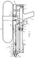
- FIG. 1 there is shown a present invention water gun 1 which includes housing 3.
- This main housing is shown with its essential components and, as is the entire figure, is illustrated in a side vertical cross-sectional view.
- a handle 5 extending from housing 3 with a trigger 7.
- a barrel 9 There is also an extending barrel 9 and an air/water pressurizable storage tank 13 with male protrusion bayonet attachment component 11.
- tank 13 is rotated and then lifted out in a bayonet type fashion in this embodiment, but may be attached by a snap lock or by a threaded neck or otherwise, or could be permanently attached with an inlet port and cap for adding water to tank 13.
- Male protrusion component 11 includes a ring seal 15 and is connected to female receiving collar 45.
- a pressurizing piston 17 which is attached to piston rod 21 and is located within chamber 19.
- Slider 25 is attached to piston rod 21 and in a movable fashion moves forward and rearward relative to extended barrel 9.
- There is a pressure release spring valve 23 which prevents overpressurization of the water gun.
- air pressure builds up within the water gun until a predetermined pressure is reached and then spring valve 23 will release excess pressure.
- the excess predetermined pressure will depend upon whether the water gun is intended to operate as a low pressure, medium pressure or high pressure water gun as previously set forth herein.
- a water gun of the desired pressure may be obtained by providing the appropriate components or adjustment of spring valve 23.
- One way valve 27 permits air to be forced into but not to be returned from chamber 19.
- tank 13 When tank 13 is removed from main housing 3 and partially filled with water, for example, half to three-quarters filled with water, it is then returned to main housing 3 by the user by inverting the water gun 1 and attaching the tank to the water gun. Then slider handle 25 is reciprocated and pressure is built up. Note that when the gun 1 is uprighted, the water from tank 13 will, at least in part, seek its lowest level through gravity and, therefore, fill up conduit 29, channel of release 31, including wider portion 33, as well as the open area within female receiving portion 45 of the connection. Thus air pressure will build up in the top of air/water pressurizable storage tank 13 and will put pressure on the water within gun 1.
- Trigger 7 has a pivot attachment 51 and extends below main housing 3 so that it may be manually activated. Its inside portion is connected to linkage 53 which is likewise connected to arm 55 which has a pivot attachment 65. This is connected to linkage or tie rod 57 which is connected also to linkage or tie rod 59 via a second, delay spring 61. This second spring 61 is a direct part of the linkage and has predetermined strength and extensions so that it operates to create a burst of flow.
- Linkage 59 passes through an O ring seal assembly 63 to maintain a seal and pressure in the channel of release. Linkage 59 is connected to plug valve 35 which seals off the channel of release to prevent water from leaving the water gun and first spring 37 biases plug valve 35 to its first, closed position.
- first spring 37 It has a second, opened position to the right of the drawing when first spring 37 is compressed.
- the linkage extends second spring 61 so that it extends to a predetermined length and, at that point, overcomes the strength of the first force, i.e., the internal water pressure and the first spring 37 to rapidly move plug valve 35 from its first, closed position to its second, opened position, thereby allowing a burst of water to flow out of the gun.
- spring 37 again closes plug valve 35.
- screen 41 is included in the front portion 39 of the channel of release beyond plug valve 35 so as to eliminate a substantial part of the turbulence and create laminar flow, or as near laminar flow as possible.
- a critical feature of the invention involves the use of two forces operating in opposite directions whereby the first force consists of both a realistically light spring biasing the plug valve closed and water pressure.
- the larger part of the first force is the water pressure holding the valve closed.
- a second force is provided by trigger pressure and the second, delay spring 61 to have adequate strength beyond a certain point of extension to overcome the first force, thereby opening the valve in a snap action.
- FIG. 2 shows a side cut view of an alternative present invention water gun 101 which includes main housing 103. There is a handle 105 extending from housing 103 with a trigger 107. There is also an extended barrel 109, a water storage tank 113 and two air/water pressurizable storage tanks 188 and 189.
- Tank 113 is attached to housing 103 with male protrusion bayonet attachment component 111 and tanks 188 and 189 are permanently attached. Tank 113 is rotated and then lifted out in a bayonet type fashion in this embodiment.
- Male protrusion component 111 includes a ring seal 115 and is connected to female receiving collar 145.
- pressurizing piston 117 which is attached to piston rod 121 and is located within chamber 119.
- Slider handle 125 is attached to piston rod 121 and in a movable fashion moves forward and rearward relative to extended barrel 109.
- tank 113 When tank 113 is removed from main housing 103 and partially filled with water, for example, half to three-quarters filled with water, it is then returned to main housing 103 by the user by inverting the water gun 101 and attaching the tank 113 to the water gun. Then slider handle 125 is reciprocated and pressure is built up. Note that when the gun 101 is uprighted, the water from tank 113 will, at least in part, seek its lowest level through gravity and, therefore, fill up conduit 129, but not channel of release 131, due to valve 181.
- Trigger 107 has a pivot attachment 151 and extends below main housing 103 so that it may be manually activated. Its inside portion is connected to linkage 153 which is likewise connected to arm 155 which has a pivot attachment 165. This is connected also to linkage or tie rod 157 which is also connected to linkage or tie rod 159 via a second, delay spring 161. This second spring 161 is a direct part of the linkage and has predetermined strength and extensions so that it operates to create a burst of flow. Linkage 159 passes through an O ring seal assembly 163 to maintain a seal and pressure in the channel of release.
- Linkage 159 is connected to plug valve 135 which seals off the channel of release 131, including wider portion 133, to prevent water from leaving the water gun, and compression spring 137 biases plug valve 135 to its first, closed position.
- Plug valve 135 has a second, opened position to the right of the drawing when compression spring 137 is compressed.
- water gun 101 also preferably includes a screen 141 in the front portion 139 of the channel of release, due to a large nozzle opening 143, e.g., 1/8 inch (31.75 mm) diameter.
- Valve 181 acts as a pressure relief valve.
- valve 181 is connected to water storage tank 113.
- valve 181 may be formed of components or adjusted to provide for operation of the water gun of the second embodiment illustrated in Figure 2 as a low pressure, medium pressure or high pressure water gun as set forth above.
Landscapes
- Engineering & Computer Science (AREA)
- General Engineering & Computer Science (AREA)
- Toys (AREA)
- Nozzles (AREA)
- Special Spraying Apparatus (AREA)
- Jet Pumps And Other Pumps (AREA)
- Fluid-Driven Valves (AREA)
- Fire-Extinguishing By Fire Departments, And Fire-Extinguishing Equipment And Control Thereof (AREA)
- Electrical Discharge Machining, Electrochemical Machining, And Combined Machining (AREA)
- Safety Valves (AREA)
- Cleaning By Liquid Or Steam (AREA)
- Spray Control Apparatus (AREA)
Claims (20)
- Wasserpistole (1, 101) mit einem Gehäuse (3, 103), einem Lauf (9, 109), mindestens einem druckbeaufschlagbaren Luft/Wasser-Vorratstank (13, 188, 189), einem Mechanismus zum Druckaufbau (17, 19, 21, 23, 25, 27, 117, 119, 121, 171, 173, 175, 181), einem Ausströmkanal (31, 33, 131, 133) zum Schießen von Wasser und einem Auslösemechanismus, umfassend:(a) einen am Gehäuse angebrachten Abzug (7, 107), von dem ein Teil aus dem Gehäuse hervorsteht, um eine manuelle Betätigung desselben zu ermöglichen,(b) ein Ventil (35, 135), das innerhalb des Ausströmkanals angeordnet ist und in einer ersten geschlossenen Stellung verhindert, dass Wasser aus dem Ausströmkanal ausfließt, sowie in einer zweiten, offenen Stellung ermöglicht, dass Wasser aus dem Ausströmkanal herausfließt, wobei das Ventil so ausgestaltet ist, dass druckbeaufschlagtes Wasser innerhalb des Ausströmkanals (31, 33, 131, 133) eine Wasserdruck-Schließkraft auf das Ventil erzeugt;(c) eine erste am Ventil angebrachte Feder (37, 137), die das Ventil in seiner ersten, geschlossenen Stellung vorspannt, wobei die erste Federkraft und die Wasserdruck-Schließkraft eine erste Kraft erzeugen;(d) ein Gestänge (53, 55, 57, 59, 61, 65, 153, 155, 157, 159, 161, 165), das mit dem Abzug (7, 107) und mit dem Ventil (35, 135) so in Verbindung steht, dass die Betätigung des Abzugs das Gestänge so bewegt, dass das Ventil von seiner ersten, geschlossenen Stellung in seine zweite, offene Stellung bewegt wird und ein Loslassen des Abzugs ermöglicht, dass die erste Feder (37, 137) das Ventil zurück in seine erste, geschlossene Stellung vorspannt;
gekennzeichnet durch einen Wasserspritzpistolen-Auslösemechanismus für einen kontrollierten Strahl, umfassend:(e) eine Verzögerungsfeder (61, 161), die als Teil des Gestänges fungiert und in diesem Gestänge zwischen dem Ventil (35, 135) und dem Abzug (7, 107) angeordnet ist, wobei, wenn der Abzug betätigt wird, die Kraft der Verzögerungsfeder überwunden werden muss, und zwar von einem Bediener, der den Abzug über eine vorbestimmte Strecke verlagert, wobei, bevor das Ventil öffnet, aufgrund der Verlagerung des Abzugs von der Verzögerungsfeder eine zweite Kraft erzeugt wird, die entgegen der ersten Kraft wirkt und wobei, wenn der Abzug um die vorbestimmte Strecke verlagert wird, die erste Kraft überwunden wird, wodurch das Ventil aus der geschlossenen Stellung bewegt und veranlasst wird, sich plötzlich in die zweite, geöffnete Stellung zu bewegen, wodurch ein die Wasserpistole verlassender Wasserstrahl erzeugt wird. - Wasserpistole (1, 101) nach Anspruch 1,
dadurch gekennzeichnet, dass die Verzögerungsfeder (61, 161) einen ersten Dehnungsbereich hat, in dem die erste, das Ventil (35, 135) in seine erste, geschlossene Stellung vorspannende Feder (37, 137) nicht überwunden wird, sowie einen zweiten Dehnungsbereich nach dem ersten Dehnungsbereich aufweist, durch den die erste Feder überwunden und das Ventil aus seiner ersten, geschlossenen Stellung in seine zweite, geöffnete Stellung bewegt wird. - Wasserpistole (1, 101) nach Anspruch 1,
dadurch gekennzeichnet, dass der Ausströmkanal (31, 33, 131, 133) eine festgelegte Querschnittsfläche aufweist und mit einem stromabwärts des Ventils (35, 135) angeordneten Auslassabschnitt (39, 139) versehen ist, und dass der Auslassabschnitt eine Mündung (43, 143) umfasst, die eine Querschnittsfläche aufweist, welche kleiner ist, als die festgelegte Querschnittsfläche des Ausdehnungskanals. - Wasserpistole (1, 101) nach Anspruch 1,
dadurch gekennzeichnet, dass der Ausströmkanal ein verwirbelungshemmendes Sieb (41, 141) enthält. - Wasserpistole (1, 101) nach Anspruch 3,
dadurch gekennzeichnet, dass der Auslassabschnitt des Ausströmkanals ein zwischen dem Ventil (35, 135) und der Mündung (43, 143) angeordnetes, verwirbelungshemmendes Sieb (41, 141) beinhaltet. - Wasserpistole (1, 101) nach Anspruch 1,
dadurch gekennzeichnet, dass das Gestänge zwei Zugstangen (57, 59, 157, 159) umfasst, zwischen denen die Verzögerungsfeder (61, 161) angeordnet ist. - Wasserpistole (1) nach Anspruch 1,
dadurch gekennzeichnet, dass die Pistole einen Tank (13) sowie eine handbetätigte Druckpumpe (17, 19, 21, 25) mit einem Überdruckventil (23) zur Vermeidung zu hoher Drücke umfasst. - Wasserpistole (101) nach einem der Ansprüche 1 bis 6,
dadurch gekennzeichnet, dass sie mehrere Wassertanks (113, 188, 189) aufweist, welche mindestens einen Luft/Wasser-Vorratstank (113) und mindestens einen druckbeaufschlagbaren Luft/Wasser-Tank (188, 189) beinhalten, welche mit dem Ausströmkanal (131) zum Flüssigkeitsaustausch in Verbindung stehen. - Mehrfachtank-Wasserpistole (101) nach Anspruch 8,
dadurch gekennzeichnet, dass die Pistole einen Luft/Wasser-Vorratstank (113) und eine handbetätigte Druckpumpe (117, 119, 121, 125) zum Druckbeaufschlagen des mindestens einen druckbeaufschlagbaren Luft/Wasser-Tanks (188, 189) umfasst. - Mehrfachtank-Wasserpistole (101) nach Anspruch 9,
dadurch gekennzeichnet, dass die handbetätigte Druckpumpe (117, 119, 121, 125) imstande ist, Wasser aus dem Vorratstank (113) zu dem mindestens einen druckbeaufschlagbaren Luft/Wasser-Tank (188, 189) zu pumpen, wodurch in dem mindestens einen druckbeaufschlagbaren Luft/Wasser-Tank (188, 189) die Wassermenge zunimmt, um das Luftvolumen zu verkleinern, wodurch der darin herrschende Luftdruck ansteigt. - Mehrfachtank-Wasserpistole (101) nach Anspruch 8,
dadurch gekennzeichnet, dass die Pistole ferner ein Überdruckventil (181) enthält, um eine Druckbeaufschlagung des mindestens einen druckbeaufschlagbaren Luft/Wasser-Tanks (188, 189) über einen bestimmten Druck hinaus zu verhindern. - Mehrfachtank-Wasserpistole (101) nach Anspruch 10,
dadurch gekennzeichnet, dass die Pistole ferner ein Überdruckventil (181) enthält, um eine Druckbeaufschlagung des mindestens einen druckbeaufschlagbaren Luft/Wasser-Tanks (188, 189) über einen bestimmten Druck hinaus zu verhindern, wobei das Überdruckventil (181) so mit dem Vorratstank (113) in Verbindung steht, dass Wasser aus dem druckbeaufschlagbaren Tank zurück in den Vorratstank gepumpt wird, wenn der genannte bestimmte Druck überschritten wird. - Wasserpistole (1, 101) nach einem der Ansprüche 7, 11 oder 12,
dadurch gekennzeichnet, dass die Pistole eine Hochdruck-Wasserpistole ist und das Überdruckventil (23, 181) bei Drücken über etwa 70 psi (4,92 kg/cm2) aktiviert wird. - Wasserpistole (1, 101) nach einem der Ansprüche 7, 11 oder 12,
dadurch gekennzeichnet, dass die Pistole eine Wasserpistole mit mittlerem Druck ist und das Überdruckventil (23, 181) bei Drücken von etwa 40 bis 70 psi (2,81 bis 4,92 kg/cm2) aktiviert wird. - Wasserpistole (1, 101) nach einem der Ansprüche 7, 11 oder 12,
dadurch gekennzeichnet, dass die Pistole eine Niedrigdruck-Wasserpistole mit Laminarströmung ist und das Überdruckventil (23, 181) bei Drücken von etwa 20 bis 40 psi (1,41 bis 2,81 kg/cm2) aktiviert wird. - Wasserpistole (1, 101) nach einem der Ansprüche 1 bis 15,
dadurch gekennzeichnet, dass das Gestänge umfasst: ein erstes Gestängeelement (53, 153), das schwenkbar mit dem Abzug (7, 107) und mit einem zweiten, abgewinkelten Gestängeelement (55, 155) verbunden ist, wobei das zweite, abgewinkelte Gestängeelement (55, 155) ebenfalls schwenkbar mit einer ersten Zugstange (57, 157) verbunden ist, welche über die Verzögerungsfeder (61, 161) mit einer zweiten Zugstange (59, 159) in Verbindung steht, wobei die zweite Zugstange mit dem Ventil (35, 135) verbunden ist. - Wasserpistole (1, 101) nach Anspruch 16,
dadurch gekennzeichnet, dass die erste Zugstange (57, 157), die zweite Zugstange (59, 159) und die Verzögerungsfeder (61, 161) axial im wesentlichen auf einer Linie liegen. - Wasserpistole (1, 101) nach einem der Ansprüche 1 bis 17,
dadurch gekennzeichnet, dass die erste Feder (37, 137) eine Druckfeder und die Verzögerungsfeder (61, 161) eine Zugfeder ist. - Wasserpistole (1, 101) nach einem der Ansprüche 1 bis 18,
dadurch gekennzeichnet, dass der mindestens eine druckbeaufschlagbare Luft/Wasser-Vorratstank (13, 188, 189) von außen direkt am Gehäuse (3, 103) befestigt ist. - Wasserpistole (101) nach einem der Ansprüche 8 bis 19,
dadurch gekennzeichnet, dass der Luft/Wasser-Vorratstank (113) von außerhalb direkt am Gehäuse (3, 103) befestigt ist.
Applications Claiming Priority (3)
| Application Number | Priority Date | Filing Date | Title |
|---|---|---|---|
| US82735 | 1993-06-28 | ||
| US08082735 US5339987B1 (en) | 1993-06-28 | 1993-06-28 | Controlled flow bursting water gun release mechanism |
| PCT/US1994/007311 WO1995000221A1 (en) | 1993-06-28 | 1994-06-28 | Controlled flow, bursting water gun release mechanism |
Publications (3)
| Publication Number | Publication Date |
|---|---|
| EP0706414A1 EP0706414A1 (de) | 1996-04-17 |
| EP0706414A4 EP0706414A4 (de) | 1996-12-04 |
| EP0706414B1 true EP0706414B1 (de) | 2001-12-19 |
Family
ID=22173109
Family Applications (1)
| Application Number | Title | Priority Date | Filing Date |
|---|---|---|---|
| EP94920830A Expired - Lifetime EP0706414B1 (de) | 1993-06-28 | 1994-06-28 | Auslösemechanismus für kontrollierten wasserstrahlverlauf bei wasserpistole |
Country Status (11)
| Country | Link |
|---|---|
| US (1) | US5339987B1 (de) |
| EP (1) | EP0706414B1 (de) |
| JP (1) | JP2848963B2 (de) |
| AT (1) | ATE211015T1 (de) |
| AU (1) | AU686194B2 (de) |
| CA (1) | CA2166107C (de) |
| DE (1) | DE69429515T2 (de) |
| FI (1) | FI110673B (de) |
| NZ (1) | NZ268542A (de) |
| TW (1) | TW262532B (de) |
| WO (1) | WO1995000221A1 (de) |
Cited By (1)
| Publication number | Priority date | Publication date | Assignee | Title |
|---|---|---|---|---|
| US10969193B2 (en) | 2017-05-26 | 2021-04-06 | Spyra GmbH | Water gun |
Families Citing this family (39)
| Publication number | Priority date | Publication date | Assignee | Title |
|---|---|---|---|---|
| US5586688A (en) * | 1994-11-25 | 1996-12-24 | Johnson Research & Development Company, Inc. | Electric pump toy water gun |
| US5878914A (en) * | 1995-03-13 | 1999-03-09 | Johnson Research & Development Company, Inc. | Toy water gun |
| US5662244A (en) * | 1995-07-14 | 1997-09-02 | Lcd International, L.L.C. | Toy weapon firing a liquid projectile |
| US6247995B1 (en) | 1996-02-06 | 2001-06-19 | Bruce Bryan | Bioluminescent novelty items |
| US5876995A (en) | 1996-02-06 | 1999-03-02 | Bryan; Bruce | Bioluminescent novelty items |
| US5822968A (en) * | 1996-04-23 | 1998-10-20 | Savala; Rodney M. | Garden tool and sprayer |
| CA2486645C (en) * | 1996-06-28 | 2006-05-30 | Larami Limited | Bladder water gun, improved bladder and nozzle |
| US5779100A (en) * | 1996-08-07 | 1998-07-14 | Johnson Research & Development Corp, Inc. | Vacuum actuated replenishing water gun |
| US5826750A (en) * | 1997-01-08 | 1998-10-27 | Johnson Research & Development Corporation, Inc. | Toy water gun with fluid selection control valve |
| US5850941A (en) * | 1997-01-08 | 1998-12-22 | Johnson Research & Development Company, Inc. | Toy water gun with air siphoning valve |
| US5799828A (en) * | 1997-03-03 | 1998-09-01 | Robert A. DeMars | Water gun |
| US5975358A (en) * | 1998-05-08 | 1999-11-02 | Patent Category Corp | Toy gun with an integrated target generator |
| US6138871A (en) * | 1998-06-11 | 2000-10-31 | Larami Limited | Single tank water gun with onboard pump and quick-charging nozzle connection |
| US6474507B1 (en) * | 1999-09-30 | 2002-11-05 | Trendmasters, Inc. | Water gun amusement device |
| US6412594B1 (en) * | 1999-10-05 | 2002-07-02 | Shoot The Moon Products Ii, Llc | Water gun with sound effects module |
| US6203397B1 (en) | 1999-11-19 | 2001-03-20 | Johnson Research & Development & Company, Inc. | convertible air and water toy gun |
| US6364162B1 (en) | 2000-01-06 | 2002-04-02 | Johnson Research & Development Co. | Automatic pressurized fluid gun |
| US6280277B1 (en) | 2000-06-27 | 2001-08-28 | Shelcore, Inc. | Combination water gun and self-propelled water toy |
| US6631830B2 (en) | 2001-08-20 | 2003-10-14 | Larami Limited | Snap action ball valve assembly and liquid dispenser using same |
| US7219817B2 (en) | 2001-10-01 | 2007-05-22 | James Samuel Panzarella | Fluid slug launcher |
| TW555029U (en) * | 2001-12-12 | 2003-09-21 | Shi-Guang Weng | Multi-purpose temperature control safety plug |
| US7163130B2 (en) * | 2002-10-18 | 2007-01-16 | Luc Marcel Lafond | Portable gas powered fluid dispenser |
| CA2552032A1 (en) * | 2003-03-04 | 2004-11-25 | Ll Lafond Intellectual Properties Inc. | Nozzle for dispensable viscous materials |
| US20040255564A1 (en) * | 2003-06-19 | 2004-12-23 | Loaces Francisco B. | Combination landscaping and herbicide spraying device |
| US20060123758A1 (en) * | 2003-06-19 | 2006-06-15 | Loaces Francisco B | Combination blower and herbicide spraying |
| US7451900B2 (en) * | 2004-06-30 | 2008-11-18 | S.C. Johnson & Son, Inc. | Delivery system |
| US7185792B2 (en) * | 2004-08-25 | 2007-03-06 | Black & Decker Inc. | Dispensing device with rack and pinion drive for nozzle valve |
| CA2487192A1 (en) * | 2004-11-05 | 2006-05-05 | Ll Lafond Intellectual Properties Inc. | Dispensing device with secondary reservior |
| US8579209B1 (en) | 2006-07-12 | 2013-11-12 | Sandia Corporation | Gas powered fluid gun with recoil mitigation |
| US20080105593A1 (en) * | 2006-11-03 | 2008-05-08 | The Procter & Gamble Company | Panoramic product display assembly |
| US20080245815A1 (en) * | 2007-04-04 | 2008-10-09 | Chor-Ming Ma | Pressurised toy water gun |
| EP2063128B1 (de) * | 2007-11-26 | 2012-10-31 | Perkins Engines Company Limited | Wasserpumpe mit einem Behälter |
| KR101059858B1 (ko) * | 2009-03-17 | 2011-08-29 | 한국과학기술원 | 완구용 물총 |
| CN102872602A (zh) * | 2012-04-01 | 2013-01-16 | 冯景亮 | 竹管枪 |
| KR101615561B1 (ko) * | 2015-03-25 | 2016-04-29 | 김소진 | 물 분사기를 구비한 놀이용 우산 |
| USD888768S1 (en) * | 2018-09-17 | 2020-06-30 | Junsheng Jiang | High pressure inflator |
| CN114949884B (zh) * | 2021-02-24 | 2025-04-25 | 杭州快唯科技有限公司 | 一种玩具水泡枪 |
| EP3992568B8 (de) * | 2021-06-18 | 2023-11-01 | Spyra GmbH | Betätigungsmechanismus für spielzeugwasserpistolen |
| WO2024209401A1 (en) * | 2023-04-05 | 2024-10-10 | Globalforce Ip Limited | Valve actuator |
Family Cites Families (22)
| Publication number | Priority date | Publication date | Assignee | Title |
|---|---|---|---|---|
| US1795684A (en) * | 1927-09-10 | 1931-03-10 | S G Adams Stamp | Lubricating device |
| US2808178A (en) * | 1954-02-05 | 1957-10-01 | Beverage Control Sales Company | Automatic registering pouring device |
| US2892576A (en) * | 1957-11-14 | 1959-06-30 | Lawrence T Ward | Metering button valve assembly |
| US3005577A (en) * | 1959-10-28 | 1961-10-24 | Otto Bernz Co Inc | Combination dispensing and excess pressure relief valve |
| US3116855A (en) * | 1961-03-22 | 1964-01-07 | James L Thomson | Toy water gun |
| US3197070A (en) * | 1963-05-06 | 1965-07-27 | Roy M Bloom | Fluid dispensing device |
| US3396876A (en) * | 1966-05-06 | 1968-08-13 | Workman Norman | Liquid food container |
| US3416710A (en) * | 1966-08-08 | 1968-12-17 | Joseph J. Roubal | Stop and feed apparatus |
| NL6901734A (de) * | 1968-04-26 | 1969-10-28 | ||
| US3580863A (en) * | 1968-05-16 | 1971-05-25 | Royal Products Co | Lather machine |
| US4214674A (en) * | 1978-05-30 | 1980-07-29 | California R & D Center | Hydro pistol with pressurized water container and with variable water ejection capability |
| US4271986A (en) * | 1978-11-17 | 1981-06-09 | Stoelting, Inc. | Drink dispenser spigot with splash deflector |
| US4239129A (en) * | 1978-11-29 | 1980-12-16 | Esposito Gary F | Water pistol and/or flashlight structure |
| US4286737A (en) * | 1980-02-22 | 1981-09-01 | Edward Gallant | Fertilizer dispenser with one-handed actuation |
| US4413972A (en) * | 1982-01-22 | 1983-11-08 | Lawson Richard L | Device for use in making doughnuts |
| US4735239A (en) * | 1986-09-19 | 1988-04-05 | Water Weenies, Inc. | Liquid projecting device |
| US4706848A (en) * | 1986-10-06 | 1987-11-17 | Andrade Bruce M D | High efficiency battery operated water gun |
| US4768681A (en) * | 1987-06-22 | 1988-09-06 | Multi Toys Corp. | Fluid action toy worn by user |
| FR2620052B1 (fr) * | 1987-09-09 | 1990-04-27 | Valois | Vaporisateur du type pompe manuelle a precompression pour utilisation avec un gaz propulseur |
| US4854480A (en) * | 1988-01-04 | 1989-08-08 | Shindo Robert S | Long range trigger-actuated squirt gun |
| GB2249268B (en) * | 1990-09-06 | 1994-08-03 | Lonnie George Johnson | Double tank pinch trigger pump water gun |
| US5074437B1 (en) * | 1990-09-06 | 1997-12-16 | Larami Limited | Pinch trigger pump water gun |
-
1993
- 1993-06-28 US US08082735 patent/US5339987B1/en not_active Expired - Lifetime
- 1993-12-04 TW TW082110266A patent/TW262532B/zh active
-
1994
- 1994-06-28 WO PCT/US1994/007311 patent/WO1995000221A1/en not_active Ceased
- 1994-06-28 CA CA002166107A patent/CA2166107C/en not_active Expired - Lifetime
- 1994-06-28 NZ NZ268542A patent/NZ268542A/en not_active IP Right Cessation
- 1994-06-28 AT AT94920830T patent/ATE211015T1/de not_active IP Right Cessation
- 1994-06-28 DE DE69429515T patent/DE69429515T2/de not_active Expired - Lifetime
- 1994-06-28 AU AU71798/94A patent/AU686194B2/en not_active Expired
- 1994-06-28 EP EP94920830A patent/EP0706414B1/de not_active Expired - Lifetime
- 1994-06-28 JP JP7503140A patent/JP2848963B2/ja not_active Expired - Lifetime
-
1995
- 1995-12-27 FI FI956277A patent/FI110673B/fi not_active IP Right Cessation
Cited By (1)
| Publication number | Priority date | Publication date | Assignee | Title |
|---|---|---|---|---|
| US10969193B2 (en) | 2017-05-26 | 2021-04-06 | Spyra GmbH | Water gun |
Also Published As
| Publication number | Publication date |
|---|---|
| US5339987B1 (en) | 2000-10-31 |
| EP0706414A1 (de) | 1996-04-17 |
| AU7179894A (en) | 1995-01-17 |
| FI956277A7 (fi) | 1995-12-28 |
| FI956277A0 (fi) | 1995-12-27 |
| JP2848963B2 (ja) | 1999-01-20 |
| US5339987A (en) | 1994-08-23 |
| FI110673B (fi) | 2003-03-14 |
| CA2166107C (en) | 1998-05-26 |
| ATE211015T1 (de) | 2002-01-15 |
| DE69429515D1 (de) | 2002-01-31 |
| JPH09500711A (ja) | 1997-01-21 |
| WO1995000221A1 (en) | 1995-01-05 |
| TW262532B (de) | 1995-11-11 |
| NZ268542A (en) | 1997-02-24 |
| DE69429515T2 (de) | 2002-08-14 |
| EP0706414A4 (de) | 1996-12-04 |
| CA2166107A1 (en) | 1995-01-05 |
| AU686194B2 (en) | 1998-02-05 |
Similar Documents
| Publication | Publication Date | Title |
|---|---|---|
| AU686194B2 (en) | Controlled flow, bursting water gun release mechanism | |
| US5238149A (en) | Pinch trigger hand pump water gun with multiple tanks | |
| US5322191A (en) | Low pressure, high volume pressurized water gun | |
| US5305919A (en) | Pinch trigger hand pump water gun with non-detachable tank | |
| US4854480A (en) | Long range trigger-actuated squirt gun | |
| US5873530A (en) | Liquid atomizing spray gun | |
| US5878914A (en) | Toy water gun | |
| US5074437A (en) | Pinch trigger pump water gun | |
| US5052587A (en) | Water gun | |
| WO2003016158A1 (en) | Snap action ball valve assembly and liquid dispenser using same | |
| US20060261087A1 (en) | Water gun amusement devices and methods of using the same | |
| US5448984A (en) | Toy that selectively shoots soft balls and water | |
| US6234347B1 (en) | Pressurized water gun with selective pressurization | |
| USRE39947E1 (en) | Toy water gun | |
| US20050167441A1 (en) | Single pump water gun with adjustable force pressure chamber | |
| US5850941A (en) | Toy water gun with air siphoning valve | |
| US5799828A (en) | Water gun | |
| US5303848A (en) | Double position bayonet connection for pressure tank | |
| US5332120A (en) | Water arrow projecting bow | |
| US5984140A (en) | Weight & spring assisted pumping actuator for fluid pressurization | |
| US20070289995A1 (en) | Steady stream water gun | |
| WO1994000208A1 (en) | Hand pump water gun with remote water source | |
| JPH0694395A (ja) | 水鉄砲 | |
| CA2084805A1 (en) | Pinch trigger pump hand water gun with multiple tanks |
Legal Events
| Date | Code | Title | Description |
|---|---|---|---|
| PUAI | Public reference made under article 153(3) epc to a published international application that has entered the european phase |
Free format text: ORIGINAL CODE: 0009012 |
|
| 17P | Request for examination filed |
Effective date: 19951216 |
|
| AK | Designated contracting states |
Kind code of ref document: A1 Designated state(s): AT BE CH DE DK ES FR GB GR IE IT LI LU MC NL PT SE |
|
| A4 | Supplementary search report drawn up and despatched |
Effective date: 19961018 |
|
| AK | Designated contracting states |
Kind code of ref document: A4 Designated state(s): AT BE CH DE DK ES FR GB GR IE IT LI LU MC NL PT SE |
|
| 17Q | First examination report despatched |
Effective date: 19990511 |
|
| GRAG | Despatch of communication of intention to grant |
Free format text: ORIGINAL CODE: EPIDOS AGRA |
|
| GRAG | Despatch of communication of intention to grant |
Free format text: ORIGINAL CODE: EPIDOS AGRA |
|
| GRAH | Despatch of communication of intention to grant a patent |
Free format text: ORIGINAL CODE: EPIDOS IGRA |
|
| GRAG | Despatch of communication of intention to grant |
Free format text: ORIGINAL CODE: EPIDOS AGRA |
|
| GRAH | Despatch of communication of intention to grant a patent |
Free format text: ORIGINAL CODE: EPIDOS IGRA |
|
| RAP1 | Party data changed (applicant data changed or rights of an application transferred) |
Owner name: LARAMI LIMITED |
|
| RIN1 | Information on inventor provided before grant (corrected) |
Inventor name: D'ANDRADE, BRUCE M. |
|
| GRAH | Despatch of communication of intention to grant a patent |
Free format text: ORIGINAL CODE: EPIDOS IGRA |
|
| GRAA | (expected) grant |
Free format text: ORIGINAL CODE: 0009210 |
|
| AK | Designated contracting states |
Kind code of ref document: B1 Designated state(s): AT BE CH DE DK ES FR GB GR IE IT LI LU MC NL PT SE |
|
| PG25 | Lapsed in a contracting state [announced via postgrant information from national office to epo] |
Ref country code: NL Free format text: LAPSE BECAUSE OF FAILURE TO SUBMIT A TRANSLATION OF THE DESCRIPTION OR TO PAY THE FEE WITHIN THE PRESCRIBED TIME-LIMIT Effective date: 20011219 Ref country code: LI Free format text: LAPSE BECAUSE OF FAILURE TO SUBMIT A TRANSLATION OF THE DESCRIPTION OR TO PAY THE FEE WITHIN THE PRESCRIBED TIME-LIMIT Effective date: 20011219 Ref country code: GR Free format text: LAPSE BECAUSE OF FAILURE TO SUBMIT A TRANSLATION OF THE DESCRIPTION OR TO PAY THE FEE WITHIN THE PRESCRIBED TIME-LIMIT Effective date: 20011219 Ref country code: CH Free format text: LAPSE BECAUSE OF FAILURE TO SUBMIT A TRANSLATION OF THE DESCRIPTION OR TO PAY THE FEE WITHIN THE PRESCRIBED TIME-LIMIT Effective date: 20011219 Ref country code: BE Free format text: LAPSE BECAUSE OF FAILURE TO SUBMIT A TRANSLATION OF THE DESCRIPTION OR TO PAY THE FEE WITHIN THE PRESCRIBED TIME-LIMIT Effective date: 20011219 Ref country code: AT Free format text: LAPSE BECAUSE OF FAILURE TO SUBMIT A TRANSLATION OF THE DESCRIPTION OR TO PAY THE FEE WITHIN THE PRESCRIBED TIME-LIMIT Effective date: 20011219 |
|
| REF | Corresponds to: |
Ref document number: 211015 Country of ref document: AT Date of ref document: 20020115 Kind code of ref document: T |
|
| REG | Reference to a national code |
Ref country code: CH Ref legal event code: EP |
|
| REG | Reference to a national code |
Ref country code: GB Ref legal event code: IF02 |
|
| REG | Reference to a national code |
Ref country code: IE Ref legal event code: FG4D |
|
| REF | Corresponds to: |
Ref document number: 69429515 Country of ref document: DE Date of ref document: 20020131 |
|
| PG25 | Lapsed in a contracting state [announced via postgrant information from national office to epo] |
Ref country code: SE Free format text: LAPSE BECAUSE OF FAILURE TO SUBMIT A TRANSLATION OF THE DESCRIPTION OR TO PAY THE FEE WITHIN THE PRESCRIBED TIME-LIMIT Effective date: 20020319 Ref country code: PT Free format text: LAPSE BECAUSE OF FAILURE TO SUBMIT A TRANSLATION OF THE DESCRIPTION OR TO PAY THE FEE WITHIN THE PRESCRIBED TIME-LIMIT Effective date: 20020319 Ref country code: DK Free format text: LAPSE BECAUSE OF FAILURE TO SUBMIT A TRANSLATION OF THE DESCRIPTION OR TO PAY THE FEE WITHIN THE PRESCRIBED TIME-LIMIT Effective date: 20020319 |
|
| NLV1 | Nl: lapsed or annulled due to failure to fulfill the requirements of art. 29p and 29m of the patents act | ||
| ET | Fr: translation filed | ||
| PG25 | Lapsed in a contracting state [announced via postgrant information from national office to epo] |
Ref country code: ES Free format text: LAPSE BECAUSE OF FAILURE TO SUBMIT A TRANSLATION OF THE DESCRIPTION OR TO PAY THE FEE WITHIN THE PRESCRIBED TIME-LIMIT Effective date: 20020627 |
|
| PG25 | Lapsed in a contracting state [announced via postgrant information from national office to epo] |
Ref country code: MC Free format text: LAPSE BECAUSE OF NON-PAYMENT OF DUE FEES Effective date: 20020628 Ref country code: LU Free format text: LAPSE BECAUSE OF NON-PAYMENT OF DUE FEES Effective date: 20020628 |
|
| REG | Reference to a national code |
Ref country code: CH Ref legal event code: PL |
|
| PLBE | No opposition filed within time limit |
Free format text: ORIGINAL CODE: 0009261 |
|
| STAA | Information on the status of an ep patent application or granted ep patent |
Free format text: STATUS: NO OPPOSITION FILED WITHIN TIME LIMIT |
|
| 26N | No opposition filed | ||
| PGFP | Annual fee paid to national office [announced via postgrant information from national office to epo] |
Ref country code: IE Payment date: 20030417 Year of fee payment: 10 |
|
| NLV1 | Nl: lapsed or annulled due to failure to fulfill the requirements of art. 29p and 29m of the patents act | ||
| PG25 | Lapsed in a contracting state [announced via postgrant information from national office to epo] |
Ref country code: IE Free format text: LAPSE BECAUSE OF NON-PAYMENT OF DUE FEES Effective date: 20040628 |
|
| REG | Reference to a national code |
Ref country code: IE Ref legal event code: MM4A |
|
| PG25 | Lapsed in a contracting state [announced via postgrant information from national office to epo] |
Ref country code: IT Free format text: LAPSE BECAUSE OF NON-PAYMENT OF DUE FEES Effective date: 20050628 |
|
| PGFP | Annual fee paid to national office [announced via postgrant information from national office to epo] |
Ref country code: FR Payment date: 20060613 Year of fee payment: 13 |
|
| REG | Reference to a national code |
Ref country code: FR Ref legal event code: ST Effective date: 20080229 |
|
| PG25 | Lapsed in a contracting state [announced via postgrant information from national office to epo] |
Ref country code: FR Free format text: LAPSE BECAUSE OF NON-PAYMENT OF DUE FEES Effective date: 20070702 |
|
| PGFP | Annual fee paid to national office [announced via postgrant information from national office to epo] |
Ref country code: DE Payment date: 20130626 Year of fee payment: 20 Ref country code: GB Payment date: 20130624 Year of fee payment: 20 |
|
| REG | Reference to a national code |
Ref country code: DE Ref legal event code: R071 Ref document number: 69429515 Country of ref document: DE |
|
| REG | Reference to a national code |
Ref country code: GB Ref legal event code: PE20 Expiry date: 20140627 |
|
| PG25 | Lapsed in a contracting state [announced via postgrant information from national office to epo] |
Ref country code: GB Free format text: LAPSE BECAUSE OF EXPIRATION OF PROTECTION Effective date: 20140627 |
|
| PG25 | Lapsed in a contracting state [announced via postgrant information from national office to epo] |
Ref country code: DE Free format text: LAPSE BECAUSE OF EXPIRATION OF PROTECTION Effective date: 20140701 |