EP0706438B1 - Vis de serrage - Google Patents
Vis de serrage Download PDFInfo
- Publication number
- EP0706438B1 EP0706438B1 EP94917778A EP94917778A EP0706438B1 EP 0706438 B1 EP0706438 B1 EP 0706438B1 EP 94917778 A EP94917778 A EP 94917778A EP 94917778 A EP94917778 A EP 94917778A EP 0706438 B1 EP0706438 B1 EP 0706438B1
- Authority
- EP
- European Patent Office
- Prior art keywords
- ring
- screw
- area
- screw member
- feed
- Prior art date
- Legal status (The legal status is an assumption and is not a legal conclusion. Google has not performed a legal analysis and makes no representation as to the accuracy of the status listed.)
- Expired - Lifetime
Links
- 210000000078 claw Anatomy 0.000 claims description 7
- 230000001105 regulatory effect Effects 0.000 claims description 7
- 238000000926 separation method Methods 0.000 claims 1
- 238000010276 construction Methods 0.000 description 4
- 238000010586 diagram Methods 0.000 description 4
- 230000003116 impacting effect Effects 0.000 description 3
- 230000003321 amplification Effects 0.000 description 1
- 230000005540 biological transmission Effects 0.000 description 1
- 230000002349 favourable effect Effects 0.000 description 1
- 230000037431 insertion Effects 0.000 description 1
- 238000003780 insertion Methods 0.000 description 1
- 238000004519 manufacturing process Methods 0.000 description 1
- 238000003199 nucleic acid amplification method Methods 0.000 description 1
- 238000007789 sealing Methods 0.000 description 1
Images


Classifications
-
- F—MECHANICAL ENGINEERING; LIGHTING; HEATING; WEAPONS; BLASTING
- F16—ENGINEERING ELEMENTS AND UNITS; GENERAL MEASURES FOR PRODUCING AND MAINTAINING EFFECTIVE FUNCTIONING OF MACHINES OR INSTALLATIONS; THERMAL INSULATION IN GENERAL
- F16D—COUPLINGS FOR TRANSMITTING ROTATION; CLUTCHES; BRAKES
- F16D7/00—Slip couplings, e.g. slipping on overload, for absorbing shock
- F16D7/04—Slip couplings, e.g. slipping on overload, for absorbing shock of the ratchet type
-
- B—PERFORMING OPERATIONS; TRANSPORTING
- B24—GRINDING; POLISHING
- B24B—MACHINES, DEVICES, OR PROCESSES FOR GRINDING OR POLISHING; DRESSING OR CONDITIONING OF ABRADING SURFACES; FEEDING OF GRINDING, POLISHING, OR LAPPING AGENTS
- B24B23/00—Portable grinding machines, e.g. hand-guided; Accessories therefor
- B24B23/02—Portable grinding machines, e.g. hand-guided; Accessories therefor with rotating grinding tools; Accessories therefor
-
- B—PERFORMING OPERATIONS; TRANSPORTING
- B24—GRINDING; POLISHING
- B24B—MACHINES, DEVICES, OR PROCESSES FOR GRINDING OR POLISHING; DRESSING OR CONDITIONING OF ABRADING SURFACES; FEEDING OF GRINDING, POLISHING, OR LAPPING AGENTS
- B24B45/00—Means for securing grinding wheels on rotary arbors
- B24B45/006—Quick mount and release means for disc-like wheels, e.g. on power tools
-
- B—PERFORMING OPERATIONS; TRANSPORTING
- B27—WORKING OR PRESERVING WOOD OR SIMILAR MATERIAL; NAILING OR STAPLING MACHINES IN GENERAL
- B27B—SAWS FOR WOOD OR SIMILAR MATERIAL; COMPONENTS OR ACCESSORIES THEREFOR
- B27B5/00—Sawing machines working with circular or cylindrical saw blades; Components or equipment therefor
- B27B5/29—Details; Component parts; Accessories
- B27B5/30—Details; Component parts; Accessories for mounting or securing saw blades or saw spindles
- B27B5/32—Devices for securing circular saw blades to the saw spindle
-
- F—MECHANICAL ENGINEERING; LIGHTING; HEATING; WEAPONS; BLASTING
- F16—ENGINEERING ELEMENTS AND UNITS; GENERAL MEASURES FOR PRODUCING AND MAINTAINING EFFECTIVE FUNCTIONING OF MACHINES OR INSTALLATIONS; THERMAL INSULATION IN GENERAL
- F16B—DEVICES FOR FASTENING OR SECURING CONSTRUCTIONAL ELEMENTS OR MACHINE PARTS TOGETHER, e.g. NAILS, BOLTS, CIRCLIPS, CLAMPS, CLIPS OR WEDGES; JOINTS OR JOINTING
- F16B33/00—Features common to bolt and nut
-
- F—MECHANICAL ENGINEERING; LIGHTING; HEATING; WEAPONS; BLASTING
- F16—ENGINEERING ELEMENTS AND UNITS; GENERAL MEASURES FOR PRODUCING AND MAINTAINING EFFECTIVE FUNCTIONING OF MACHINES OR INSTALLATIONS; THERMAL INSULATION IN GENERAL
- F16D—COUPLINGS FOR TRANSMITTING ROTATION; CLUTCHES; BRAKES
- F16D1/00—Couplings for rigidly connecting two coaxial shafts or other movable machine elements
- F16D1/06—Couplings for rigidly connecting two coaxial shafts or other movable machine elements for attachment of a member on a shaft or on a shaft-end
-
- F—MECHANICAL ENGINEERING; LIGHTING; HEATING; WEAPONS; BLASTING
- F16—ENGINEERING ELEMENTS AND UNITS; GENERAL MEASURES FOR PRODUCING AND MAINTAINING EFFECTIVE FUNCTIONING OF MACHINES OR INSTALLATIONS; THERMAL INSULATION IN GENERAL
- F16D—COUPLINGS FOR TRANSMITTING ROTATION; CLUTCHES; BRAKES
- F16D41/00—Freewheels or freewheel clutches
- F16D41/12—Freewheels or freewheel clutches with hinged pawl co-operating with teeth, cogs, or the like
-
- Y—GENERAL TAGGING OF NEW TECHNOLOGICAL DEVELOPMENTS; GENERAL TAGGING OF CROSS-SECTIONAL TECHNOLOGIES SPANNING OVER SEVERAL SECTIONS OF THE IPC; TECHNICAL SUBJECTS COVERED BY FORMER USPC CROSS-REFERENCE ART COLLECTIONS [XRACs] AND DIGESTS
- Y10—TECHNICAL SUBJECTS COVERED BY FORMER USPC
- Y10S—TECHNICAL SUBJECTS COVERED BY FORMER USPC CROSS-REFERENCE ART COLLECTIONS [XRACs] AND DIGESTS
- Y10S411/00—Expanded, threaded, driven, headed, tool-deformed, or locked-threaded fastener
- Y10S411/919—Screw having driving contacts
Definitions
- the present invention relates to a screw for fastening a rotational tool, such as the grindstone of a hand grinder or a circular hand saw, for example, to the drive shaft of an electrically powered tool, as per the preamble of claim 1.
- a rotational tool such as the grindstone of a hand grinder or a circular hand saw
- An example of such a screw is disclosed in EP 330 672 B.
- a rotational tool such as the grindstone or circular saw mentioned above
- a flange and bolt are formed on the end of the drive shaft, the rotational tool is impaled on the bolt portion and a nut screwed onto the outside thereof, and the nut is fastened to secure the rotational tool between the said nut and the abovementioned flange.
- the document EP 0 330 672 B1 shows a fastening device for axially tightening a rotational tool, such as the grindstone of a hand grinder or a circular hand saw, against a flange arranged on a drive shaft having, at its end, a thread for screwing said fastening device onto this drive shaft by means of a screw member, and comprising a flange ring subjectable to an axial clamping force by the screw member and the tool is pressed against an inner flange, and comprising an operating ring fitted around the outer circumferential area at the end portion of the drive shaft rotatable relative to the screw member, inputs the operational rotational force.
- a rotational tool such as the grindstone of a hand grinder or a circular hand saw
- This known device uses an epicyclical gearing to increase the hand power.
- the manufacturing of such epicyclical gears is difficult and expensive, further, for geometrical reasons, allows only a certain step-down, so that not every requested step-down can be produced.
- the epicyclical gear needs a larger construction size so that the clamping device for axially tightening a tool cannot be used without more ado at machines with a normal thread portion at the drive spindle for the tightening of such a disc-like tool.
- the present invention aims to provide a screw for fastening whereby the screw member can be readily removed by preventing the screw member from becoming too tight due to the rotational force caused by reaction to use of the rotational tool in an impacting fashion.
- a rotational force is input by fitting the screw of the screw member to the screw area on the side where the object to be attached is and turning the operating ring in the fastening direction, whereupon the screw member also turns in the fastening direction under the frictional resistance of the internal structural elements and is screwed onto the screw area where the object to be attached is.
- the screw feed ring is supported via the holding ring in a state off-center of the operating ring and, therefore, the screw feed ring revolves under the rotation of the operating ring, and part of the female screw area of the screw feed ring is screwed onto the male screw area on the screw member side and, therefore, the screw feed ring is screw fed to the flange ring side accompanying the revolution mentioned above, and this screw feeding action is transmitted to the flange ring and the relevant surface of the said flange ring is pressured, under the force in the thrust direction, into contact with the object to be attached, which is thereby secured.
- the operating ring when the attached object is to be removed, the operating ring is rotated in the opposite direction to that mentioned above (the unfastening direction). Because there is a high pressure-contact load from the flange ring on the object to be attached in the initial stages of the rotation, then, if the operating ring is rotated in the opposite direction, the screw feed ring can rotate backwards under a rotational force of increased torque in the same way as described above, the said screw feed ring can be returned to the initial position prior to screw feeding, and the pressure contacting of the flange ring on the object to be fitted is released by this returning action, and, therefore, the load from the flange ring side of the screw member is released, the rotation of the operating ring is transmitted to the screw member by the frictional resistance of the internal structural elements, and the screw member can be made to rotate in reverse and can be removed by turning the operating ring.
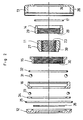
- the figures show a screw for fastening which has been formed in a nut shape: in Figure 1 and Figure 2, the said screw 10 for fastening comprises a screw member 11, a flange ring 12, an operating ring 13, a reverse screw ring 14, a screw-feed ring 15, a holding ring 16, an O-ring 17 which is a rotation-transmitting member, and a torque limiter 18; and, by way of example, the screw 10 for fastening secures the rotational tool 22, which is the object to be attached, for example the grindstone of a hand grinder, between itself and an inner flange 21 attached to the drive shaft 19 of an electrically powered tool by screwing onto the attachment bolt 20 of the said drive shaft 19.
- the said screw 10 for fastening comprises a screw member 11, a flange ring 12, an operating ring 13, a reverse screw ring 14, a screw-feed ring 15, a holding ring 16, an O-ring 17 which is a rotation-transmitting member, and a torque limiter 18; and, by way of example
- the screw member 11 of the screw 10 for fastening mentioned above is provided on the inner circumference of its shaft core portion with a female screw 23 which screws onto the attachment bolt 20 of the abovementioned drive shaft 19, it has stepped areas formed on both the inside and outside edges of its outer circumferential area, it has a flange ring 12 rotatably fitted around its inside edge, and it has the regulating area 24 of the operating ring 13 rotatably fitted around its outside edge side.
- the inside of the abovementioned operating ring 13 is formed in a recessed shape, thereby forming a space within it, and the inside of its outside edge overlaps with the outer circumferential area of the abovementioned flange ring 12, and an O-ring 25 is inserted to seal the said overlapping portion. Further, a knurled rim 26 is formed at the outer circumferential area of the abovementioned operating ring 13, thereby facilitating manual rotational input.
- a male screw area 27 is provided on the outer circumferential area of the abovementioned screw member 11 in the central area sandwiched between the stepped areas at both edges, and a female screw area 28 provided on the inner circumference of the abovementioned reverse screw ring 14 is screwed onto this male screw area 27 so that, when a rotational force is applied to this reverse screw ring 14, the reverse screw ring 14 is screw fed slightly forwards or backwards within a range regulated by the regulating area 24 of the operating ring 13 and the torque limiter 18, for example a range of about 1 mm.
- the abovementioned O-ring 17 is inserted in the region where the outer circumference on the outside edge of the abovementioned reverse screw ring 14 and the inner circumferential area of the abovementioned operating ring 13 face each other, this O-ring 17 being provided not only for its sealing action, but also to rotate the reverse screw ring 14 by transmitting the rotational force of the operating ring 13 by frictional resistance, and also to slip the transmission when the return screw ring 14 experiences a load from the flange ring 12 side.
- a male screw area 29 is provided on the outer circumferential area of the abovementioned return screw ring 14, while a female screw area 30 with a screw diameter slightly larger than that of, and a screw pitch the same as that of the abovementioned male screw area 29 is provided on the inner circumferential surface of the abovementioned screw feed ring 15, and the screw feed ring 15 is off-centred by an off-centring amount e such that part of the said female screw area 30 meshes with the above male screw area 29, and the holding ring 16 holds this off-center position of the screw feed ring 15 via bearings 31.
- the holding ring 16 is secured by insertion under pressure against the recessed inner surface of the operating ring 13. Further, an O-ring 32 is inserted between the abovementioned screw feed ring 15 and the holding ring 16.
- Thrust bearings 33 are inserted between the facing surfaces of the abovementioned holding ring 16 and the abovementioned flange ring 12, and the said thrust bearings 33 are held in a retainer 34 fitted into a recess in the flange ring 12.
- the abovementioned torque limiter 18 comprises a resilient ring 35, and a plurality of recessed areas 37 in the flange ring 12 which engage with a plurality of claws 36 formed in this resilient ring 35.
- Spline channels 38 are provided in the inner circumferential area of the abovementioned resilient ring 35, and the spline channels 38 engage with spline claws 39 formed in the recesses of the stepped area on the inside of the screw member 11 with which they turn in an integral fashion. Further, the plurality of claws 36 ...
- arms 40 which resiliently alter position in the inward and outward direction, and the arms 40 will alter position and slip to cut off any driving forces if a rotational force larger than the resiliency set in the arms 40 is transmitted from the flange ring 12 to the resilient ring 35.
- the flange ring 12 side of the screw 10 for fastening is made to face the side with the rotational tool 22, the female screw 23 of the screw member 11 of the screw 10 for fastening is fitted to the attachment bolt 20, and the knurled rim 26 portion of the operating ring 13 is turned directly by hand in the fastening direction, thereby screwing on the female screw 23.
- the return screw ring 14 is screw fed by the meshing of the male and female screw areas 27 and 28 under the frictional resistance of the O-ring 17 (a feed of about 1 mm), and the inside edge comes into contact with the resilient ring 35 of the torque limiter 18 and is regulated, slip occurs between the O-ring 17 and the return screw ring 14 and only the turning operation of the operating ring 13 is permitted.
- the screw feed ring 15 is supported, via the holding ring 16, in a state off-centred from the operating ring 13, and, therefore, the screw feed ring 15 revolves under the rotation of the operating ring 13, and, because part of the female screw area 30 of the screw feed ring 15 is meshed with the male screw area 29 of the reverse screw ring 14, the screw feed ring 15 is screw fed (feed of about 1 mm) to the flange ring 12 side, and this screw feeding is transmitted by the bearing 31, the holding ring 16 and the thrust bearings 33 to the flange ring 12, and the said side face of the said flange ring 12 is pressured into contact with the rotational tool 22 and secures it under the force in the thrust direction.
- the operating ring 13 is rotated in the opposite direction to that mentioned above (the unfastening direction). Because there is a high pressure-contact load from the flange ring 12 on the rotational tool 22 in the initial stages of the rotation, if the operating ring 13 is rotated in the opposite direction, the operating ring 13 and the O-ring 17, which is the rotation-transmitting member, slip and the screw feed ring 15 revolves and withdraws until the pressure contact of the flange ring 12 is relaxed.
- the rotation of the operating ring 13 causes the reverse screw ring 14 to withdraw via the O-ring 17 and, if this withdrawal proceeds to the position regulated by the regulating area 24 of the operating ring 13, then the abovementioned screw feed ring 15 and the reverse screw ring 14 can be returned to the initial position.
- the operating ring 13 is again turned in the removal direction, then the whole unit turns under internal resistance as described above and the screw member 11 is made to turn backwards and can be removed from the attachment bolt 20.
- the screw member 11 in the above embodiment was formed in a nut shape by providing a female screw 23 in its core area, but it can also be constructed in a bolt form by providing a male screw 41 in the core area of the screw member 11 as shown in Figure 4.
- 42 is a hexagonal hole and is constructed such that it can be turned by a hexagonal wrench. A detailed explanation of the rest of the construction is omitted in view of the fact that it is the same as the embodiment described above.
- the rotational tool 22 is secured in pressurized contact under the force of the flange ring 12 in the thrust direction, and this pressurized contact has no energy component in the direction of rotation and, therefore, the screw member 11 can be reliably prevented from being over-tightened due to rotational forces stemming from the reaction to use of the rotational tool 22 in an impactive fashion, and the screw member 11 can be readily removed.
- the impact load of the rotational tool 22 mentioned above is cut off by the torque limiter 18 so that damage to the rotational tool 22 by the impact load can be prevented and, at the same time, damage to the internal parts of the screw 10 for fastening can also be prevented.
- the flange ring 12 is pressed under the force of increased torque of the screw feed ring 15, a substantial fastening force and a strong loosening force are obtained at the flange ring 12 for a minor rotational input at the operating ring 13, and the device can be strongly fastened and loosened by a direct manual rotating operation without using a force-enhancing tool.
- the screw feed ring 15 can be more reliably returned to its initial position and a favourable state of use is achieved.
- this invention can provide a screw for fastening which can be constructed compactly and has good operational properties.
- the screw 10 for fastening can be constructed by forming the screw member 11 and the reverse screw ring 14 in the embodiment integrally.
- the torque limiter 18 shown in the embodiment described above may be omitted and the flange ring 12 may be directly connected to the screw member 11 by spline fitting. In this case, better results are obtained by arranging the construction such that there is somewhat more play in the spline fitting and movement in the axial direction is easy.
Landscapes
- Engineering & Computer Science (AREA)
- General Engineering & Computer Science (AREA)
- Mechanical Engineering (AREA)
- Life Sciences & Earth Sciences (AREA)
- Wood Science & Technology (AREA)
- Forests & Forestry (AREA)
- Transmission Devices (AREA)
- Details Of Spanners, Wrenches, And Screw Drivers And Accessories (AREA)
- Gripping On Spindles (AREA)
- Constituent Portions Of Griding Lathes, Driving, Sensing And Control (AREA)
- Dowels (AREA)
Claims (12)
- Vis (10) pour la fixation d'un outil (22) tournant, tel que la meule d'un meuleur à main ou d'une scie circulaire à main comportant un élément (11) formant vis ayant une vis (23) femelle formée dans sa zone de coeur, une bague (12) formant rebord qui est adaptée autour de la zone circonférentielle extérieure d'un bord de l'élément (11) formant vis de manière à pouvoir tourner relativement par rapport à l'élément (11) formant vis, et dont la surface extérieure vient en contact avec l'objet à fixer, une bague (13) d'actionnement pouvant tourner par rapport à l'élément (11) formant vis, bague (13) d'actionnement qui fait face à la bague (12) formant rebord mentionnée précédemment, en étant séparée de celle-ci d'une distance de séparation prescrite, et qui fournit la force fonctionnelle de rotation caractérisée parle fait que la bague (13) d'actionnement est adaptée autour de la zone circonférentielle extérieure à l'autre bord de l'élément (11) formant vis mentionné précédemment, par une bague (15) d'alimentation de vis positionnée dans l'intervalle entre la bague (12) formant rebord mentionnée précédemment et la bague (13) d'actionnement mentionnée précédemment, qui est maintenue décentrée en ayant une partie de sa zone (30) de vis femelle, qui est disposée sur sa partie circonférentielle intérieure pertinente, qui engrène avec la zone (27) de vis mâle disposée sur la zone circonférentielle extérieure de l'élément (11) formant vis dans ledit intervalle de positionnement, et qui transmet l'alimentation de vis créée par la révolution à la bague (12) formant rebord mentionnée précédemment dans la direction de poussée, par une bague (16) de maintien adaptée autour de la zone circonférentielle extérieure de la bague (15) d'alimentation de vis mentionnée précédemment, qui permet une révolution de la bague (15) d'alimentation de vis en maintenant la bague (15) d'alimentation de vis décentrée.
- Dispositif Suivant la revendication 1, caractérisé en ce que la bague (16) de maintien est séparée de la bague (13) d'actionnement.
- Dispositif suivant l'une des revendications 1 ou 2, caractérisé par une bague (14) formant vis inverse régulée à une quantité d'alimentation de vis déterminée à l'avance qui est vissée sur la circonférence extérieure de l'élément (11) formant vis, la circonférence extérieure de la bague (14) formant vis inverse est munie d'une zone (29) de vis mâle engrenant avec une partie de la zone (28) de la vis femelle de la bague (15) d'alimentation de vis, et qui est insérée entre l'élément (11) formant vis et la bague (15) d'alimentation de vis.
- Dispositif suivant l'une ou plusieurs des revendications 1 à 3, caractérisé en ce que la rotation de la bague (13) d'actionnement est transmise à l'élément (11) formant vis par résistance interne des divers éléments formés sur l'intérieur de la bague (13) d'actionnement.
- Dispositif suivant la revendication 4, caractérisé par un élément (17) de transmission de rotation, qui transmet la rotation de la bague (13) d'actionnement à la bague (14) de vis inverse et qui glisse à une charge supérieure à une charge déterminée à l'avance.
- Dispositif suivant l'une des revendications 4 ou 5, caractérisé en ce que la résistance de frottement comporte une bague torique d'étanchéité (17 ; 32).
- Dispositif suivant l'une ou plusieurs des revendications 4 à 6, caractérisé par une connexion (32) de frottement entre la bague (16) de maintien et la bague (15) d'alimentation de vis.
- Dispositif suivant l'une ou plusieurs des revendications 1 à 7, caractérisé en ce qu'un dispositif (18) de limitation de couple est disposé antre l'élément (11) formant vis et la bague (12) formant rebord.
- Dispositif suivant la revendication 8, caractérisé an ce que le dispositif (18) de limitation de couple comporte une bague (35) élastique ayant des griffes (36) et étant reliée à l'élément (11) formant vis d'une manière solidaire en rotation, les griffes (36) pénétrant dans des zones (37) évidées reliées à la bague (12) formant rebord d'une manière solidaire en rotation.
- Dispositif suivant la revendication 9, caractérisé en ce que la bague (35) élastique comporte des canaux (38) en forme de cannelures coopérant avec des griffes (39) on forme de cannelures formées sur l'élément (11) formant vis.
- Dispositif suivant l'une ou plusieurs des revendications 1 à 10, caractérisé on ce que l'élément (11) formant vis comporte une vis (41) mâle formée dans sa zone de coeur.
- Dispositif suivant l'une ou plusieurs des revendications 1 à 11, caractérisé on ce que l'intérieur de la bague (13) d'actionnement est formée suivant une forme évidée, formant ainsi un espace on son sein, et l'intérieur de son bord extérieur chevauche la zone circonférentielle extérieure de la bague (12) formant rebord, la bague (15) d'alimentation de vis étant ainsi positionnée dans l'espace entre la bague (12) formant rebord et la bague (13) d'actionnement.
Applications Claiming Priority (4)
| Application Number | Priority Date | Filing Date | Title |
|---|---|---|---|
| JP18920893 | 1993-06-30 | ||
| JP5189208A JPH0727121A (ja) | 1993-06-30 | 1993-06-30 | 締付け用ネジ |
| JP189208/93 | 1993-06-30 | ||
| PCT/IB1994/000182 WO1995001240A1 (fr) | 1993-06-30 | 1994-06-27 | Vis de serrage |
Publications (2)
| Publication Number | Publication Date |
|---|---|
| EP0706438A1 EP0706438A1 (fr) | 1996-04-17 |
| EP0706438B1 true EP0706438B1 (fr) | 2000-02-16 |
Family
ID=16237353
Family Applications (1)
| Application Number | Title | Priority Date | Filing Date |
|---|---|---|---|
| EP94917778A Expired - Lifetime EP0706438B1 (fr) | 1993-06-30 | 1994-06-27 | Vis de serrage |
Country Status (9)
| Country | Link |
|---|---|
| US (1) | US5810533A (fr) |
| EP (1) | EP0706438B1 (fr) |
| JP (1) | JPH0727121A (fr) |
| CN (1) | CN1128002A (fr) |
| AU (1) | AU674588B2 (fr) |
| BR (1) | BR9406874A (fr) |
| CA (1) | CA2159107A1 (fr) |
| DE (1) | DE69423045T2 (fr) |
| WO (1) | WO1995001240A1 (fr) |
Cited By (1)
| Publication number | Priority date | Publication date | Assignee | Title |
|---|---|---|---|---|
| EP3894132B1 (fr) | 2019-01-23 | 2022-10-26 | Saccardo Gcf S.R.L. | Électro-broche |
Families Citing this family (38)
| Publication number | Priority date | Publication date | Assignee | Title |
|---|---|---|---|---|
| AU699271B2 (en) * | 1994-12-22 | 1998-11-26 | Power Tool Holders Incorporated | Clamp screw |
| JPH09250528A (ja) * | 1996-01-08 | 1997-09-22 | Jacobs Japan Inc | 締付け用ネジ |
| US6273659B1 (en) | 1997-02-17 | 2001-08-14 | Power Tool Holders Incorporated | Locking mechanism for a rotary working member |
| US6050741A (en) * | 1998-01-30 | 2000-04-18 | Power Tool Holders Incorporated | Tool clamping device |
| US6439091B1 (en) * | 1999-04-19 | 2002-08-27 | Black & Decker Inc. | Clutch mechanism |
| KR100610548B1 (ko) * | 1999-08-30 | 2006-08-09 | 에누티쯔루 가부시키가이샤 | 공구유지구 및 공구유지구용 진동 수정구 |
| KR20000063820A (ko) * | 2000-08-04 | 2000-11-06 | 송영근 | 가상모의 골프 경기 서비스를 통한 비지니스 모델 |
| US7013987B2 (en) * | 2000-09-08 | 2006-03-21 | Black & Decker | Clutch assembly and clamp mechanism for rotary tool disc |
| DE10056211A1 (de) * | 2000-11-13 | 2002-05-23 | Neudecker & Jolitz Gmbh & Co | Schnellspannmutter |
| US6645058B2 (en) | 2000-11-30 | 2003-11-11 | Black & Decker Inc. | Clamp mechanism for rotary tool disc |
| US6702090B2 (en) | 2001-03-14 | 2004-03-09 | Milwaukee Electric Tool Corporation | Power tool and spindle lock system |
| US7063201B2 (en) | 2001-11-27 | 2006-06-20 | Milwaukee Electric Tool Corporation | Power tool and spindle lock system |
| DE10258372B4 (de) | 2001-12-12 | 2004-12-30 | S-B Power Tool Company, Broadview | Spannaufbau |
| DE10205848C2 (de) * | 2002-02-13 | 2003-12-04 | Metabowerke Gmbh | Spannmutter zum Fixieren eines scheibenförmigen Werkzeugs |
| US7184520B1 (en) * | 2003-01-29 | 2007-02-27 | Varian Medical Systems Technologies, Inc. | Component mounting system with stress compensation |
| DE10308743B3 (de) * | 2003-02-28 | 2004-11-11 | Hilti Ag | Schnellspannmutter für scheibenförmige Werkzeuge |
| JP4100329B2 (ja) * | 2003-11-07 | 2008-06-11 | 株式会社豊田自動織機 | 動力伝達機構及びその組立方法 |
| JP4519514B2 (ja) * | 2004-04-28 | 2010-08-04 | 株式会社マキタ | 固定ナット |
| US20060024142A1 (en) * | 2004-08-02 | 2006-02-02 | Ducret Lucien C | Torque-limiting stud |
| US7954857B2 (en) * | 2006-04-27 | 2011-06-07 | Diba Industries, Inc. | Assembly of multi-use torque fitting and length of tubing having compressible seal |
| US20070254744A1 (en) * | 2006-04-27 | 2007-11-01 | Diba Industries, Inc. | Multi-use torque fitting |
| US20070266837A1 (en) * | 2006-05-22 | 2007-11-22 | Nickels Richard C | Clamp assembly |
| US7984933B2 (en) * | 2008-02-28 | 2011-07-26 | Diba Industries, Inc. | Multi-use torque fitting and compressible ferrule |
| JP5193282B2 (ja) * | 2008-03-07 | 2013-05-08 | ナブテスコ株式会社 | 回り止め機構付きのボルトとナット |
| US20110044584A1 (en) * | 2009-08-19 | 2011-02-24 | Diba Industries, Inc. | Optical fiber connection assembly |
| DE102010004272B4 (de) * | 2010-01-09 | 2011-09-22 | Norma Germany Gmbh | Kupplungselement |
| EP2482143A1 (fr) * | 2011-01-26 | 2012-08-01 | Nivarox-FAR S.A. | Assemblage par blocage à cliquet |
| CN105916647B (zh) * | 2013-11-25 | 2018-11-16 | 罗伯特·博世有限公司 | 用于锯片的免工具螺栓系统 |
| CN104191228B (zh) * | 2014-09-18 | 2016-08-24 | 南通同洲电子有限责任公司 | 用于高频头的螺纹的电动对接装置 |
| CN104400744B (zh) * | 2014-09-18 | 2016-10-19 | 南通同洲电子有限责任公司 | 用于高频头的螺纹的自控下的对接装置及其对接方法 |
| US9874464B2 (en) * | 2014-12-18 | 2018-01-23 | Wastequip, Llc | Sensor mount |
| EP3476539A1 (fr) * | 2017-10-27 | 2019-05-01 | HILTI Aktiengesellschaft | Dispositif de serrage et machine-outil manuelle |
| US10711815B2 (en) * | 2018-09-20 | 2020-07-14 | The Boeing Company | Indexing pins, indexing clamps, and methods of aligning a first body and a second body of a structure |
| US10690160B2 (en) * | 2018-09-20 | 2020-06-23 | The Boeing Company | Methods of aligning a first body and a second body of a structure |
| US11578812B2 (en) * | 2018-12-21 | 2023-02-14 | Rain Bird Corporation | Solenoid adapter |
| US11441611B2 (en) * | 2019-02-27 | 2022-09-13 | Carefusion 303, Inc. | Torque limiting connector |
| CN115672244B (zh) * | 2022-10-27 | 2023-06-13 | 安徽沙丰新材料有限公司 | 一种螺带式反应器 |
| US11971114B1 (en) | 2023-01-06 | 2024-04-30 | Rain Bird Corporation | Solenoid adapter |
Citations (1)
| Publication number | Priority date | Publication date | Assignee | Title |
|---|---|---|---|---|
| EP0330672B1 (fr) * | 1987-01-15 | 1991-07-03 | Robert Bosch Gmbh | Dispositif de serrage pour le blocage axial d'un outil, notamment d'une meule |
Family Cites Families (30)
| Publication number | Priority date | Publication date | Assignee | Title |
|---|---|---|---|---|
| US3614900A (en) * | 1970-05-08 | 1971-10-26 | Wahlmark Systems | Anti-friction drive |
| DE2059528A1 (de) * | 1970-12-03 | 1972-06-08 | Gaertner Robert | Schraubenantrieb |
| DE2811328C2 (de) * | 1978-03-16 | 1986-09-25 | Robert Bosch Gmbh, 7000 Stuttgart | Bohrfutter |
| EP0034640B1 (fr) * | 1980-02-25 | 1983-09-21 | Robert Dr. Gärtner | Mécanisme à vis |
| DE3012836C2 (de) * | 1980-04-02 | 1985-09-26 | Licentia Patent-Verwaltungs-Gmbh, 6000 Frankfurt | Einrichtung zum Festspannen der Schleifscheibe von Winkelschleifern |
| US4434586A (en) * | 1980-12-03 | 1984-03-06 | Robert Bosch Gmbh | Machine tool, especially a hand-held power tool with a turnable clamping element for clamping a tool on the tool spindle |
| DE3523746A1 (de) * | 1985-07-03 | 1987-01-08 | Metabowerke Kg | Schnellspannvorrichtung fuer rotierende scheibenfoermige werkzeuge |
| DE3603384A1 (de) * | 1986-02-05 | 1987-08-06 | Bosch Gmbh Robert | Vorrichtung zum loesbaren befestigen eines scheibenfoermigen werkzeugs |
| DE3613987A1 (de) * | 1986-04-25 | 1987-10-29 | Metabowerke Kg | Vorrichtung zum loesbaren befestigen einer schleifscheibe |
| JPH049471Y2 (fr) * | 1986-05-19 | 1992-03-10 | ||
| DE3643067A1 (de) * | 1986-12-17 | 1988-06-23 | Bosch Gmbh Robert | Spanneinrichtung zum axialen festspannen eines werkzeuges, insbesondere einer scheibe |
| DE3644979A1 (de) * | 1986-12-24 | 1988-07-07 | Pav Praezisions Apparatebau Ag | Messkluppe |
| DE3644441A1 (de) * | 1986-12-24 | 1988-07-07 | Bosch Gmbh Robert | Spanneinrichtung zum loesbaren befestigen eines werkzeuges, insbesondere einer scheibe |
| DE3702142C2 (de) * | 1987-01-24 | 1995-09-21 | Bosch Gmbh Robert | Spanneinrichtung zum axialen Festspannen eines Werkzeuges, insbesondere eines als Scheibe ausgestalteten spanenden Werkzeuges |
| DE3824040C1 (en) * | 1987-02-21 | 1989-11-23 | Robert Bosch Gmbh, 7000 Stuttgart, De | Clamping device for axially clamping a tool, in particular a disk |
| DE3705638C1 (de) * | 1987-02-21 | 1988-09-08 | Bosch Gmbh Robert | Spanneinrichtung zum axialen Festspannen eines scheibenfoermigen Werkzeuges,insbesondere einer Schleifscheibe,an einem Flansch einer angetriebenen Spindel |
| DE3841181A1 (de) * | 1988-12-07 | 1990-06-13 | Bosch Gmbh Robert | Handwerkzeugmaschine mit einer mehrteiligen handbetaetigbaren schnellspanneinrichtung |
| US4864884A (en) * | 1988-08-01 | 1989-09-12 | Dana Corporation | Ball nut and means for attaching a mounting flange thereto |
| DE3903766A1 (de) * | 1989-02-09 | 1990-08-16 | Licentia Gmbh | Schnellspanneinrichtung fuer scheibenfoermige bearbeitungswerkzeuge von elektrowerkzeugen |
| DE3903765A1 (de) * | 1989-02-09 | 1990-08-16 | Licentia Gmbh | Schnellspanneinrichtung fuer scheibenfoermige bearbeitungswerkzeuge von elektrowerkzeugen |
| HUT70006A (en) * | 1990-09-12 | 1995-09-28 | Matthews | Fastener particularly for grinding wheel |
| DE4031725A1 (de) * | 1990-10-06 | 1992-04-09 | Bosch Gmbh Robert | Schnellspanneinrichtung, insbesondere zum befestigen scheibenfoermiger werkzeuge an einer antriebsspindel einer handwerkzeugmaschine |
| DE4102420A1 (de) * | 1991-01-28 | 1992-07-30 | Bosch Gmbh Robert | Handwerkzeugmaschine, insbesondere winkelschleifmaschine |
| US5088581A (en) * | 1991-01-30 | 1992-02-18 | Eaton Corporation | One-way clutch |
| JPH081805Y2 (ja) * | 1991-03-20 | 1996-01-24 | リョービ株式会社 | 工具の着脱装置 |
| GB9204345D0 (en) * | 1992-02-28 | 1992-04-08 | Black & Decker Inc | Improvements in or relating to flange locks |
| JP3280715B2 (ja) * | 1992-08-31 | 2002-05-13 | 大治郎 中村 | 締付け用ネジ |
| DE4243328C1 (de) * | 1992-12-22 | 1994-06-09 | Metabowerke Kg | Schnellspanneinrichtung zum axialen Festspannen eines scheibenförmigen Werkzeugs |
| DE4238466C1 (de) * | 1992-11-16 | 1994-01-20 | Metabowerke Kg | Schnellspanneinrichtung zum axialen Festspannen eines scheibenförmigen Werkzeugs |
| DE4305317C2 (de) * | 1993-02-20 | 1995-10-12 | Metabowerke Kg | Schnellspanneinrichtung zum axialen Festspannen eines scheibenförmigen Werkzeugs |
-
1993
- 1993-06-30 JP JP5189208A patent/JPH0727121A/ja active Pending
-
1994
- 1994-06-27 EP EP94917778A patent/EP0706438B1/fr not_active Expired - Lifetime
- 1994-06-27 CN CN94192927A patent/CN1128002A/zh active Pending
- 1994-06-27 DE DE69423045T patent/DE69423045T2/de not_active Expired - Fee Related
- 1994-06-27 US US08/556,956 patent/US5810533A/en not_active Expired - Fee Related
- 1994-06-27 CA CA002159107A patent/CA2159107A1/fr not_active Abandoned
- 1994-06-27 WO PCT/IB1994/000182 patent/WO1995001240A1/fr not_active Ceased
- 1994-06-27 BR BR9406874A patent/BR9406874A/pt not_active IP Right Cessation
- 1994-06-27 AU AU69357/94A patent/AU674588B2/en not_active Ceased
Patent Citations (1)
| Publication number | Priority date | Publication date | Assignee | Title |
|---|---|---|---|---|
| EP0330672B1 (fr) * | 1987-01-15 | 1991-07-03 | Robert Bosch Gmbh | Dispositif de serrage pour le blocage axial d'un outil, notamment d'une meule |
Cited By (1)
| Publication number | Priority date | Publication date | Assignee | Title |
|---|---|---|---|---|
| EP3894132B1 (fr) | 2019-01-23 | 2022-10-26 | Saccardo Gcf S.R.L. | Électro-broche |
Also Published As
| Publication number | Publication date |
|---|---|
| WO1995001240A1 (fr) | 1995-01-12 |
| BR9406874A (pt) | 1996-03-26 |
| JPH0727121A (ja) | 1995-01-27 |
| DE69423045D1 (de) | 2000-03-23 |
| US5810533A (en) | 1998-09-22 |
| AU674588B2 (en) | 1997-01-02 |
| DE69423045T2 (de) | 2001-01-25 |
| EP0706438A1 (fr) | 1996-04-17 |
| AU6935794A (en) | 1995-01-24 |
| CN1128002A (zh) | 1996-07-31 |
| CA2159107A1 (fr) | 1995-01-12 |
Similar Documents
| Publication | Publication Date | Title |
|---|---|---|
| EP0706438B1 (fr) | Vis de serrage | |
| EP0588483B1 (fr) | Vis de serrage | |
| US5577872A (en) | Torque enhancing tightening screw | |
| US6793023B2 (en) | Hand power tool | |
| EP1184581B1 (fr) | Dispositif de fixation fileté | |
| US3937036A (en) | Rotary driving tool having a torque responsive clutch | |
| JP3071523B2 (ja) | スクリュードライバーにおける回り止め装置 | |
| KR19980063436A (ko) | 개선된 볼나사 조임기구 | |
| US9022137B2 (en) | Fastening tool | |
| EP1211027B1 (fr) | Dispositif de serrage de disque d'usinage | |
| US5567100A (en) | Torque enhancing clamping nut | |
| US4472985A (en) | Fastening tool | |
| JP2000304024A (ja) | 電動工具におけるロックナットの緩み防止機構 | |
| US5622373A (en) | Chucking device | |
| US4901832A (en) | Freewheel drive for the starter of an internal combustion engine | |
| KR100556041B1 (ko) | 전동드라이버 | |
| GB2178680A (en) | Driving tools for screw-threaded fasteners | |
| KR960016089B1 (ko) | 조여 붙임용 나사부 | |
| JPH04360703A (ja) | 軸等の固定構造 | |
| JPH11325021A (ja) | ナット及びボルト・ナット | |
| JP3076149B2 (ja) | ナット締め込み装置 | |
| CZ158893A3 (en) | Screw-like element secured against unscrewing | |
| JPH10231910A (ja) | 変速機構付き減速機 | |
| JPH07148606A (ja) | ツールチャック | |
| HK1024438A1 (en) | Automatic shaft lock |
Legal Events
| Date | Code | Title | Description |
|---|---|---|---|
| PUAI | Public reference made under article 153(3) epc to a published international application that has entered the european phase |
Free format text: ORIGINAL CODE: 0009012 |
|
| 17P | Request for examination filed |
Effective date: 19951227 |
|
| AK | Designated contracting states |
Kind code of ref document: A1 Designated state(s): CH DE GB IT LI NL SE |
|
| 17Q | First examination report despatched |
Effective date: 19960717 |
|
| GRAG | Despatch of communication of intention to grant |
Free format text: ORIGINAL CODE: EPIDOS AGRA |
|
| GRAG | Despatch of communication of intention to grant |
Free format text: ORIGINAL CODE: EPIDOS AGRA |
|
| GRAH | Despatch of communication of intention to grant a patent |
Free format text: ORIGINAL CODE: EPIDOS IGRA |
|
| GRAH | Despatch of communication of intention to grant a patent |
Free format text: ORIGINAL CODE: EPIDOS IGRA |
|
| GRAA | (expected) grant |
Free format text: ORIGINAL CODE: 0009210 |
|
| AK | Designated contracting states |
Kind code of ref document: B1 Designated state(s): CH DE GB IT LI NL SE |
|
| REG | Reference to a national code |
Ref country code: CH Ref legal event code: EP |
|
| PGFP | Annual fee paid to national office [announced via postgrant information from national office to epo] |
Ref country code: NL Payment date: 20000320 Year of fee payment: 7 |
|
| REF | Corresponds to: |
Ref document number: 69423045 Country of ref document: DE Date of ref document: 20000323 |
|
| ITF | It: translation for a ep patent filed | ||
| REG | Reference to a national code |
Ref country code: CH Ref legal event code: NV Representative=s name: SPIERENBURG HELMLE-KOLB & PARTNER AG PATENT- UND M |
|
| PGFP | Annual fee paid to national office [announced via postgrant information from national office to epo] |
Ref country code: GB Payment date: 20000502 Year of fee payment: 7 |
|
| PGFP | Annual fee paid to national office [announced via postgrant information from national office to epo] |
Ref country code: SE Payment date: 20000602 Year of fee payment: 7 |
|
| PGFP | Annual fee paid to national office [announced via postgrant information from national office to epo] |
Ref country code: CH Payment date: 20000621 Year of fee payment: 7 |
|
| EN | Fr: translation not filed | ||
| PLBE | No opposition filed within time limit |
Free format text: ORIGINAL CODE: 0009261 |
|
| STAA | Information on the status of an ep patent application or granted ep patent |
Free format text: STATUS: NO OPPOSITION FILED WITHIN TIME LIMIT |
|
| 26N | No opposition filed | ||
| PG25 | Lapsed in a contracting state [announced via postgrant information from national office to epo] |
Ref country code: GB Free format text: LAPSE BECAUSE OF NON-PAYMENT OF DUE FEES Effective date: 20010627 |
|
| PGFP | Annual fee paid to national office [announced via postgrant information from national office to epo] |
Ref country code: DE Payment date: 20010627 Year of fee payment: 8 |
|
| PG25 | Lapsed in a contracting state [announced via postgrant information from national office to epo] |
Ref country code: SE Free format text: LAPSE BECAUSE OF NON-PAYMENT OF DUE FEES Effective date: 20010628 |
|
| PG25 | Lapsed in a contracting state [announced via postgrant information from national office to epo] |
Ref country code: LI Free format text: LAPSE BECAUSE OF NON-PAYMENT OF DUE FEES Effective date: 20010630 Ref country code: CH Free format text: LAPSE BECAUSE OF NON-PAYMENT OF DUE FEES Effective date: 20010630 |
|
| PG25 | Lapsed in a contracting state [announced via postgrant information from national office to epo] |
Ref country code: NL Free format text: LAPSE BECAUSE OF NON-PAYMENT OF DUE FEES Effective date: 20020101 |
|
| EUG | Se: european patent has lapsed |
Ref document number: 94917778.6 |
|
| GBPC | Gb: european patent ceased through non-payment of renewal fee |
Effective date: 20010627 |
|
| REG | Reference to a national code |
Ref country code: CH Ref legal event code: PL |
|
| NLV4 | Nl: lapsed or anulled due to non-payment of the annual fee |
Effective date: 20020101 |
|
| PG25 | Lapsed in a contracting state [announced via postgrant information from national office to epo] |
Ref country code: DE Free format text: LAPSE BECAUSE OF NON-PAYMENT OF DUE FEES Effective date: 20030101 |
|
| PG25 | Lapsed in a contracting state [announced via postgrant information from national office to epo] |
Ref country code: IT Free format text: LAPSE BECAUSE OF NON-PAYMENT OF DUE FEES Effective date: 20050627 |