EP0706446B1 - Composite, procede et appareil permettant de le produire - Google Patents
Composite, procede et appareil permettant de le produire Download PDFInfo
- Publication number
- EP0706446B1 EP0706446B1 EP94920218A EP94920218A EP0706446B1 EP 0706446 B1 EP0706446 B1 EP 0706446B1 EP 94920218 A EP94920218 A EP 94920218A EP 94920218 A EP94920218 A EP 94920218A EP 0706446 B1 EP0706446 B1 EP 0706446B1
- Authority
- EP
- European Patent Office
- Prior art keywords
- ptfe
- layer
- resin
- press
- virgin
- Prior art date
- Legal status (The legal status is an assumption and is not a legal conclusion. Google has not performed a legal analysis and makes no representation as to the accuracy of the status listed.)
- Expired - Lifetime
Links
Images



Classifications
-
- B—PERFORMING OPERATIONS; TRANSPORTING
- B29—WORKING OF PLASTICS; WORKING OF SUBSTANCES IN A PLASTIC STATE IN GENERAL
- B29C—SHAPING OR JOINING OF PLASTICS; SHAPING OF MATERIAL IN A PLASTIC STATE, NOT OTHERWISE PROVIDED FOR; AFTER-TREATMENT OF THE SHAPED PRODUCTS, e.g. REPAIRING
- B29C43/00—Compression moulding, i.e. applying external pressure to flow the moulding material; Apparatus therefor
- B29C43/32—Component parts, details or accessories; Auxiliary operations
- B29C43/44—Compression means for making articles of indefinite length
-
- B—PERFORMING OPERATIONS; TRANSPORTING
- B29—WORKING OF PLASTICS; WORKING OF SUBSTANCES IN A PLASTIC STATE IN GENERAL
- B29C—SHAPING OR JOINING OF PLASTICS; SHAPING OF MATERIAL IN A PLASTIC STATE, NOT OTHERWISE PROVIDED FOR; AFTER-TREATMENT OF THE SHAPED PRODUCTS, e.g. REPAIRING
- B29C43/00—Compression moulding, i.e. applying external pressure to flow the moulding material; Apparatus therefor
- B29C43/006—Pressing and sintering powders, granules or fibres
-
- B—PERFORMING OPERATIONS; TRANSPORTING
- B29—WORKING OF PLASTICS; WORKING OF SUBSTANCES IN A PLASTIC STATE IN GENERAL
- B29C—SHAPING OR JOINING OF PLASTICS; SHAPING OF MATERIAL IN A PLASTIC STATE, NOT OTHERWISE PROVIDED FOR; AFTER-TREATMENT OF THE SHAPED PRODUCTS, e.g. REPAIRING
- B29C43/00—Compression moulding, i.e. applying external pressure to flow the moulding material; Apparatus therefor
- B29C43/02—Compression moulding, i.e. applying external pressure to flow the moulding material; Apparatus therefor of articles of definite length, i.e. discrete articles
- B29C43/14—Compression moulding, i.e. applying external pressure to flow the moulding material; Apparatus therefor of articles of definite length, i.e. discrete articles in several steps
- B29C43/146—Compression moulding, i.e. applying external pressure to flow the moulding material; Apparatus therefor of articles of definite length, i.e. discrete articles in several steps for making multilayered articles
-
- B—PERFORMING OPERATIONS; TRANSPORTING
- B29—WORKING OF PLASTICS; WORKING OF SUBSTANCES IN A PLASTIC STATE IN GENERAL
- B29C—SHAPING OR JOINING OF PLASTICS; SHAPING OF MATERIAL IN A PLASTIC STATE, NOT OTHERWISE PROVIDED FOR; AFTER-TREATMENT OF THE SHAPED PRODUCTS, e.g. REPAIRING
- B29C43/00—Compression moulding, i.e. applying external pressure to flow the moulding material; Apparatus therefor
- B29C43/02—Compression moulding, i.e. applying external pressure to flow the moulding material; Apparatus therefor of articles of definite length, i.e. discrete articles
- B29C43/20—Making multilayered or multicoloured articles
- B29C43/203—Making multilayered articles
-
- B—PERFORMING OPERATIONS; TRANSPORTING
- B29—WORKING OF PLASTICS; WORKING OF SUBSTANCES IN A PLASTIC STATE IN GENERAL
- B29C—SHAPING OR JOINING OF PLASTICS; SHAPING OF MATERIAL IN A PLASTIC STATE, NOT OTHERWISE PROVIDED FOR; AFTER-TREATMENT OF THE SHAPED PRODUCTS, e.g. REPAIRING
- B29C43/00—Compression moulding, i.e. applying external pressure to flow the moulding material; Apparatus therefor
- B29C43/22—Compression moulding, i.e. applying external pressure to flow the moulding material; Apparatus therefor of articles of indefinite length
- B29C43/228—Compression moulding, i.e. applying external pressure to flow the moulding material; Apparatus therefor of articles of indefinite length using endless belts feeding the material between non-rotating pressure members, e.g. vibrating pressure members
-
- B—PERFORMING OPERATIONS; TRANSPORTING
- B30—PRESSES
- B30B—PRESSES IN GENERAL
- B30B5/00—Presses characterised by the use of pressing means other than those mentioned in the preceding groups
- B30B5/04—Presses characterised by the use of pressing means other than those mentioned in the preceding groups wherein the pressing means is in the form of an endless band
- B30B5/06—Presses characterised by the use of pressing means other than those mentioned in the preceding groups wherein the pressing means is in the form of an endless band co-operating with another endless band
- B30B5/065—Presses characterised by the use of pressing means other than those mentioned in the preceding groups wherein the pressing means is in the form of an endless band co-operating with another endless band using anti-friction means for the pressing band
-
- B—PERFORMING OPERATIONS; TRANSPORTING
- B29—WORKING OF PLASTICS; WORKING OF SUBSTANCES IN A PLASTIC STATE IN GENERAL
- B29C—SHAPING OR JOINING OF PLASTICS; SHAPING OF MATERIAL IN A PLASTIC STATE, NOT OTHERWISE PROVIDED FOR; AFTER-TREATMENT OF THE SHAPED PRODUCTS, e.g. REPAIRING
- B29C43/00—Compression moulding, i.e. applying external pressure to flow the moulding material; Apparatus therefor
- B29C43/02—Compression moulding, i.e. applying external pressure to flow the moulding material; Apparatus therefor of articles of definite length, i.e. discrete articles
- B29C43/027—Compression moulding, i.e. applying external pressure to flow the moulding material; Apparatus therefor of articles of definite length, i.e. discrete articles having an axis of symmetry
- B29C2043/029—Compression moulding, i.e. applying external pressure to flow the moulding material; Apparatus therefor of articles of definite length, i.e. discrete articles having an axis of symmetry using axial compression along a longitudinal axis
-
- B—PERFORMING OPERATIONS; TRANSPORTING
- B29—WORKING OF PLASTICS; WORKING OF SUBSTANCES IN A PLASTIC STATE IN GENERAL
- B29C—SHAPING OR JOINING OF PLASTICS; SHAPING OF MATERIAL IN A PLASTIC STATE, NOT OTHERWISE PROVIDED FOR; AFTER-TREATMENT OF THE SHAPED PRODUCTS, e.g. REPAIRING
- B29C2791/00—Shaping characteristics in general
- B29C2791/001—Shaping in several steps
-
- B—PERFORMING OPERATIONS; TRANSPORTING
- B29—WORKING OF PLASTICS; WORKING OF SUBSTANCES IN A PLASTIC STATE IN GENERAL
- B29C—SHAPING OR JOINING OF PLASTICS; SHAPING OF MATERIAL IN A PLASTIC STATE, NOT OTHERWISE PROVIDED FOR; AFTER-TREATMENT OF THE SHAPED PRODUCTS, e.g. REPAIRING
- B29C67/00—Shaping techniques not covered by groups B29C39/00 - B29C65/00, B29C70/00 or B29C73/00
- B29C67/02—Moulding by agglomerating
- B29C67/04—Sintering
-
- B—PERFORMING OPERATIONS; TRANSPORTING
- B29—WORKING OF PLASTICS; WORKING OF SUBSTANCES IN A PLASTIC STATE IN GENERAL
- B29K—INDEXING SCHEME ASSOCIATED WITH SUBCLASSES B29B, B29C OR B29D, RELATING TO MOULDING MATERIALS OR TO MATERIALS FOR MOULDS, REINFORCEMENTS, FILLERS OR PREFORMED PARTS, e.g. INSERTS
- B29K2027/00—Use of polyvinylhalogenides or derivatives thereof as moulding material
- B29K2027/12—Use of polyvinylhalogenides or derivatives thereof as moulding material containing fluorine
- B29K2027/18—PTFE, i.e. polytetrafluoroethylene, e.g. ePTFE, i.e. expanded polytetrafluoroethylene
-
- B—PERFORMING OPERATIONS; TRANSPORTING
- B29—WORKING OF PLASTICS; WORKING OF SUBSTANCES IN A PLASTIC STATE IN GENERAL
- B29K—INDEXING SCHEME ASSOCIATED WITH SUBCLASSES B29B, B29C OR B29D, RELATING TO MOULDING MATERIALS OR TO MATERIALS FOR MOULDS, REINFORCEMENTS, FILLERS OR PREFORMED PARTS, e.g. INSERTS
- B29K2105/00—Condition, form or state of moulded material or of the material to be shaped
- B29K2105/06—Condition, form or state of moulded material or of the material to be shaped containing reinforcements, fillers or inserts
- B29K2105/16—Fillers
-
- B—PERFORMING OPERATIONS; TRANSPORTING
- B29—WORKING OF PLASTICS; WORKING OF SUBSTANCES IN A PLASTIC STATE IN GENERAL
- B29K—INDEXING SCHEME ASSOCIATED WITH SUBCLASSES B29B, B29C OR B29D, RELATING TO MOULDING MATERIALS OR TO MATERIALS FOR MOULDS, REINFORCEMENTS, FILLERS OR PREFORMED PARTS, e.g. INSERTS
- B29K2105/00—Condition, form or state of moulded material or of the material to be shaped
- B29K2105/25—Solid
- B29K2105/251—Particles, powder or granules
-
- B—PERFORMING OPERATIONS; TRANSPORTING
- B29—WORKING OF PLASTICS; WORKING OF SUBSTANCES IN A PLASTIC STATE IN GENERAL
- B29K—INDEXING SCHEME ASSOCIATED WITH SUBCLASSES B29B, B29C OR B29D, RELATING TO MOULDING MATERIALS OR TO MATERIALS FOR MOULDS, REINFORCEMENTS, FILLERS OR PREFORMED PARTS, e.g. INSERTS
- B29K2627/00—Use of polyvinylhalogenides or derivatives thereof for preformed parts, e.g. for inserts
- B29K2627/12—Use of polyvinylhalogenides or derivatives thereof for preformed parts, e.g. for inserts containing fluorine
- B29K2627/18—PTFE, i.e. polytetrafluoroethylene, e.g. ePTFE, i.e. expanded polytetrafluoroethylene
-
- B—PERFORMING OPERATIONS; TRANSPORTING
- B29—WORKING OF PLASTICS; WORKING OF SUBSTANCES IN A PLASTIC STATE IN GENERAL
- B29K—INDEXING SCHEME ASSOCIATED WITH SUBCLASSES B29B, B29C OR B29D, RELATING TO MOULDING MATERIALS OR TO MATERIALS FOR MOULDS, REINFORCEMENTS, FILLERS OR PREFORMED PARTS, e.g. INSERTS
- B29K2707/00—Use of elements other than metals for preformed parts, e.g. for inserts
- B29K2707/04—Carbon
-
- Y—GENERAL TAGGING OF NEW TECHNOLOGICAL DEVELOPMENTS; GENERAL TAGGING OF CROSS-SECTIONAL TECHNOLOGIES SPANNING OVER SEVERAL SECTIONS OF THE IPC; TECHNICAL SUBJECTS COVERED BY FORMER USPC CROSS-REFERENCE ART COLLECTIONS [XRACs] AND DIGESTS
- Y10—TECHNICAL SUBJECTS COVERED BY FORMER USPC
- Y10S—TECHNICAL SUBJECTS COVERED BY FORMER USPC CROSS-REFERENCE ART COLLECTIONS [XRACs] AND DIGESTS
- Y10S425/00—Plastic article or earthenware shaping or treating: apparatus
- Y10S425/055—Polytetrafluoroethylene, i.e. PTFE
-
- Y—GENERAL TAGGING OF NEW TECHNOLOGICAL DEVELOPMENTS; GENERAL TAGGING OF CROSS-SECTIONAL TECHNOLOGIES SPANNING OVER SEVERAL SECTIONS OF THE IPC; TECHNICAL SUBJECTS COVERED BY FORMER USPC CROSS-REFERENCE ART COLLECTIONS [XRACs] AND DIGESTS
- Y10—TECHNICAL SUBJECTS COVERED BY FORMER USPC
- Y10T—TECHNICAL SUBJECTS COVERED BY FORMER US CLASSIFICATION
- Y10T428/00—Stock material or miscellaneous articles
- Y10T428/31504—Composite [nonstructural laminate]
- Y10T428/3154—Of fluorinated addition polymer from unsaturated monomers
- Y10T428/31544—Addition polymer is perhalogenated
Definitions
- the present invention relates to compression molding two or more layers of powdered polytetrafluoroethylene (PTFE) resin and composite products made by such compression molding. More particularly, the present invention relates to forming composite articles by compression molding wherein the finished article exhibits two distinct layers or areas of material, preferably one of filled PTFE and one of virgin PTFE.
- PTFE powdered polytetrafluoroethylene
- PTFE Polytetrafluoroethylene
- Compression molding involves placing a layer of PTFE resin under sufficient pressure to create a preform that can be sintered into a finished shape, which is usually then coined.
- Isostatic molding involves filling the void between a rigid molding surface and a flexible bladder with PTFE resin. The bladder is then pressurized, and squeezes the resin between the bladder and the molding surface. The bladder is then removed and the resin is sintered.
- Isostatic molding is expensive and cumbersome, but is well-suited for forming complex and intricate shapes such as valve linings.
- the body of the valve itself can be used as the molding surface, thus permitting the valve lining to be formed in situ without requiring secondary shaping or cutting operations.
- compression molding remains the simplest and most economic method of producing PTFE articles.
- Sheets, bars or other shapes of compression molded PTFE are used to create many useful articles that take advantage of its low coefficient of friction and chemically impervious nature.
- the structural characteristics of a shape formed from virgin PTFE are less than ideal for many situations. It is known, for example, that virgin PTFE exhibits a large degree of cold flow (i.e., "creep") when exposed to continuous loads at elevated temperatures. For example, at 3.4 MPa (34 Bar, 500 psi) and 22.7°C (73° F), virgin PTFE will cold flow from an initial deformation of O.9% to about 1.8% in 10,000 hours. At 100°C (212° F), an initial deformation of 3.5% would increase to approximately 7% in the same time period.
- PTFE exhibits deformation due to compressive stress. At stress levels of 3.4 MPa (34 Bar, 500 psi) and at a temperature 22.7°C (73° F), this strain is almost negligible, while at 148.8°C (300° F) the strain at this loading is about 5%. A similar strain level, 5% , is exhibited at 22.7°C (73°F) when the compressive stress is raised to about 13 MPa (130 Bar, 1,900 psi). Thus, in applications where the PTFE component is under a compressive load and/or exposed to elevated temperatures, cold flow and deformation due to compressive stress are important considerations.
- filler materials are well known in the art of forming shapes from PTFE. See “Selecting the Right 'Teflon' TFE Compound For Best Performance," Journal of " Teflon “ Volume 13, No. 2 (1972).
- filler materials include glass fibers, carbon, graphite, bronze and molybendum disulfide (MoS 2 ) .
- MoS 2 molybendum disulfide
- PTFE resins can be compounded with fillers to increase strength characteristics such as stiffness and resistance to cold flow, to increase thermal conductivity, and to increase hardness and resistance to wear.
- any filler raises the low coefficient of friction exhibited by parts formed from virgin PTFE resins and that the increases in hardness and resistance to wear result in an article that abrades or wears cooperatingsurfaces.
- Modified PTFE resins are currently available that provide products exhibiting improved resistance to cold flow without sacrificing the low coefficient of friction of virgin PTFE. Additionally, products made from these modified resins have been found to exhibit better "weldability', to themselves and other PTFE products when used in compression molding. Examples of such modified PTFE resins are TFM1600 (Registered Trade Mark) and TFM1700 (Registered Trade Mark) sold by Hoechst, and TG70J (Registered Trade Mark) and TG170J (Registered Trade Mark) sold by Dupont. One example of such a resin is disclosed in U.S. Patent No. 4,408,007--Kuhls. In some instances the use of such resins is economically impractical since they cost between about 50% and 180% more than standard virgin PTFE.
- U.S. Patent No. 5,064,593 discloses a method of compression molding a preform from powdered PTFE resin using a rigid compression mold assembly comprising the steps of depositing a first layer comprising a first type of PTFE resin into a compression mold assembly, depositing a second layer comprising a second type of PTFE resin onto the first layer and compressing the first and second layers within the compression mold assembly at a preform pressure to create a preform.
- the U.S. Patent 5,064,593 does not disclose the method steps of partially compressing the first layer within the compression mold assembly. As will be mentioned later such a method step is known from U.S. Patent No.
- an axial compressive pressure of between 13.6 to 170 MPa (136 to 1700 Bar, 2,000 to 25,000 psi) is applied to fully compress unsintered billets into a preform, which is then sintered at 343°C to 398°C (650°F to 750° F) for two to 48 hours.
- a "sandwich" PTFE structure consisting of a layer of unfilled PTFE between two filled layers is disclosed in U.S. Patent Nos. 4,961,891 and 4,900,629, both to Pitolaj.
- the disclosed composite structure is said to be highly compressible and is made by fusing sheets of PTFE together using calendar rolls.
- the resulting laminate is then sintered at 343°C (650° F).
- a multi-layer PTFE seal is also disclosed in U.S. Patent No. 4,147,824--Dettmann et al.
- the disclosed seal comprises an outer layer and a porous layer made by washing a filler material from the PTFE.
- the first layer is fully compressed with a pressure of 30 MPa (300 bar, 4,410 psi) and a second, filled layer is added and compressed with the same pressure.
- the resulting preform is then sintered and the filler material washed out, leaving a porous layer.
- Isostatic molding can also be used to create composite structures from homogeneous preforms of different types of PTFE to achieve a unitary non-homogeneous structure, as shown in U.S. Patent Nos 4,267,237 and 4,102,966 both to Duperray et al.
- the preforms must be compressed by a pressure of at least 1 MPa (10 bar, 147 psi) since compression using lesser pressures will create preforms that are too brittle to be handled.
- the preforms are placed in an isostatic mold and further compressed to fuse them together or fuse them with a layer of powdered resin using isostatic pressures between 10 and 100 MPa (100 and 1,000 bar, 1,470 and 14,700 psi).
- the lubricant is pumped through PTFE pressure pads and provides a layer of lubricant between the pads and the bands, in addition to acting as a heat transfer medium.
- the PTFE pressure pads are attached to the platens that transfer vertical compression force provided by hydraulic cylinders. As seen in FIGS. 2-3, the pressure pads 52 are held in removable carrier trays 50 that form part of the press platens.
- the carrier trays 50 have angled dovetail slots 54 to retain the lateral edges of the PTFE pads 52 while retaining plates 56 are affixed to the perimeter of the carrier trays 50 to secure the pressure pads 52 in place.
- the lubricating fluid flows through passages 53 in the pads 52 and lubricates the bands.
- PTFE is the preferred pressure pad material.
- the operating temperatures 182-199°C (360-390°F) and pressures 2.04-3.4 MPa (20.4-34 Bar, 300-500 psi) are relatively high, the PTFE exhibits a significant degree of cold flow, ultimately leading to the "smeared" failure mode described above.
- the first layer is comprised of a filled PTFE resin and the second layer is comprised of virgin PTFE resin, most preferably a modified virgin resin that is resistant to cold flow.
- the partial compression pressure is less than 1 MPa (147 psi), preferably less than 0.1 MPa (1 Bar, 14.7 psi),and most preferably less than 10 kPa (0.1 Bar, 1.5 psi).
- the method of the present invention is useful for producing a variety of products, including sheets and cylinders.
- the method may also be used to produce other composite structures.
- the method can also include the steps of adding one or more further layers of a PTFE resin and partially compressing the layers prior to the step of compressing the layer with the preform pressure.
- the invention further provides articles of manufacture comprising a first layer of filled PTFE and a second layer of virgin PTFE, manufactured by the process of sintering and coining a preform comprised of the first and second layers, wherein the preform is manufactured in accordance with the method claimed in claim 1.
- One particular preferred embodiment of such articles is a pressure pad for use in a particleboard manufacturing apparatus.
- an article made in accordance with the present invention comprises a sliding surface of a layer of modified virgin PTFE and a second layer of filled, modified PTFE having significantly better resistance to cold flow than the virgin PTFE, such as modified PTFE with a carbon filler material.
- the present invention provides a superior product by using modified virgin PTFE resins, which have been found to provide superior binding strength between layers. In any embodiment, however, the present invention uses compression molding equipment.
- the present invention provides methods whereby PTFE articles can be manufactured from two types of PTFE resin and as a result, exhibit distinct properties on different surfaces and/or improved overall properties.
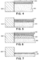
- FIGS. 4-7 there is shown a broken away cross-sectional view of a compression mold 200 during the various steps that comprise the creation of a preform in accordance with an embodiment of the present invention.
- portions of the compression mold apparatus such as the bottom pusher used 25 to revise the resin in the mold are omitted.
- a rigid lower section of the compression mold 200 is provided and is filled with a first type of powdered PTFE resin 100.
- the first resin 100 will include a filler material, most preferably carbon.
- a series of pushers 210 form part of the rigid compression mold assembly. As seen in FIG. 5 the relatively rigid pushers 210 are lowered against the first layer of PTFE resin 100 and partially compress this layer.
- partial compression refers to a process whereby PTFE resin powder is compressed by a pressure of less than 3.4 MPa (34 bar, 500 psi), the pressure being an average pressure determined by dividing the overall area of the pusher 210 contacting the surface of the resin by the magnitude of the force that urges the pusher 210 in compression.
- one reduces the pressure during partial compression to less than 0.1 MPa (1 bar, 14.7 psi).
- Certain useful embodiments in fact, utilize pressures of less than 10 kPa (0.1 bar, 1.5 psi).
- a second layer of powdered PTFE resin 102 is deposited within the mold.
- this layer is comprised of virgin PTFE and is most preferably a modified PTFE resin such as TFM1600 (Registered Trade Mark) and TFM1700 (Registered Trade Mark) sold by Hoechst, and TG 70J (Registered Trade Mark) and TG 170J (Registered Trade Mark) sold by DuPont, referenced above.
- the pusher bars or other form of rigid molding tool 210 are then used to fully compress both the first and second PTFE layers 100,102.
- the term "fully compress” refers to the pressure normally applied to a particular powdered resin or resins to fully preform the powder prior to subsequent processing steps such as sintering and coining.
- the pressure applied to fully compress the composite structures formed with the present invention is normally between about 20 to 100 MPa (200 to 1.000 bar, 2,940 to 14,700 psi). This procedure imparts a mechanically compressed effect to the preform. It should be realized that the properties of the preform will vary with both the partial compression and full compression pressures, as well as the comparable shrinkage rates and material grades for the PTFE resins.
- the present invention takes advantage of the characteristics of modified PTFE resins. It has been found that certain modified resins act as a binding agent between composite layers. In any embodiment, however, the present invention permits a preform to be created that contains at least two types of PTFE resin in two distinct layers and does so in a way that ensures a fully laminated structure while maintaining the integrity of the layers.
- a compression molded sheet (approximately 15.9 mm (5/8 inch) thick, 1.22 x 122 m (48 X 48 inches) is formed by first pouring a layer of a filled modified powdered PTFE resin (TFM 1700 (Registered Trade Mark) and 20% carbon filler) into the compression mold and partially preforming this layer using a very low pressure of about 2.7 kPa (0.027 bar, 0.4 psi). Next a layer of virgin modified powdered PTFE resin (TFM 1600) (Registered Trade Mark) is added to the compression mold cavity and this layer and the first layer are fully compressed at a pressure of about 30-60 MPa (300-600 bar, 4,410-8,820 psi).
- the resulting composite preform preferably has a layer of filled PTFE that is 12.7 mm (1/2 inch) thick, while the layer of virgin resin is about 3.2mm(1/8 inch) thick.
- the fully compressed preform is then sintered at about 370°C (700°F) for about twenty-four hours, and coined in accordance with conventional practice.
- the resulting non-homogeneous composite sheet may then be cut or machined into components, such as the particleboard forming machinery pressure pads described above.
- the material provides a layer of low friction, modified PTFE against which the stainless steel belts will slide, while also providing improved resistance to creep, and thus resistance to "smearing" by way of the layer of filled PTFE.
- FIG. 8 it can be seen that at the temperature range in which the particleboard machinery operates, a composite article made as above exhibits markedly better resistance to deformation than virgin PTFE while retaining the desirable low coefficient of friction exhibited by virgin PTFE. Moreover, the cost of the overall sheet is considerably reduced, since the filler added to the modified virgin PTFE resin is only about 10% of the cost of virgin unfilled PTFE.
- FIG. 9 depicts a composite structure made in accordance with a further embodiment of the present invention wherein a layer of filled PTFE 100 is disposed between two layers of virgin PTFE 102,103, made in accordance with the method discussed above It will be appreciated that any combination of layers of filled and unfilled PTFE resins may be combined using the techniques disclosed herein. Those of ordinary skill will be able to select desired material properties and by designing a composite sheet having the appropriate proportions of different resins, the desired properties will be achieved.
- FIG. 10A depicts a composite sheet 110 comprising a filled PTFE sheet 112 with an area 114 of virgin PTFE around its perimeter.
- This composite sheet 110 is formed by the process shown in FIG. 10B wherein a compression mold 220 contains the sheet 110 and a thin frame 222 separates the virgin sheet 112 and the filled (area 114. The frame 222 is removed and the powdered resins are partially compressed in the manner explained above, using a relatively low pressure.
- Fig. 1OC illustrates a cross-section taken along line C-C in Fig. 10A. As also shown in Fig.
- additional layers of powdered virgin PTFE 116,118 are spread across the sheet 100 to cover the exposed surface.
- the resulting composite structure is then fully compressed into a preform and sintered.
- the resulting article is a sheet of PTFE that has a layer of virgin PTFE on all exposed sides (or only certain exposed sides in other embodiments) and an encapsulated "core', of less expensive filled PTFE that also exhibits properties that vary from virgin resin, such as improved resistance to cold flow.
- Embodiments made in accordance with this example are not necessarily rectangular, but may be any shape, for example, a circle of filled resin within a square frame of virgin resin. Moreover, in some instances, it will be desirable to cut, or otherwise machine the resulting composite sheet.
- FIG. 11 illustrates a side view, in cross-section of a cylindrical preform.
- the preform is preferably comprised of an inner layer of virgin PTFE 120, an intermediate layer of filled PTFE 122 and an outer layer of virgin PTFE 124.
- this preform can be constructed using a cylindrical mold in conjunction with thin separators to permit the required layers of resin to be deposited.
- the preform shown is partially compressed using a relatively low pressure. After partial compression, additional layers of virgin PTFE 126,128, shown in FIG.
- the present invention takes advantage of the improved properties of modified PTFE resins.
- the methods disclosed herein can be used with virtually any type of PTFE resin and any type of filler material to produce useful products in an economical manner.
- the filled resin will be the most expensive component and layers or areas of virgin resin can be used where the properties of the filled resin are not needed.
- a benefit of the present invention is that the methods disclosed herein can be performed using conventional compression molding equipment, e.g., molds, presses, punches, ovens, etc. The only additional equipment needed in some embodiments is the thin flexible inserts that separate areas of different types of resin.
Landscapes
- Engineering & Computer Science (AREA)
- Mechanical Engineering (AREA)
- Casting Or Compression Moulding Of Plastics Or The Like (AREA)
- Manufacture Of Alloys Or Alloy Compounds (AREA)
Claims (15)
- Procédé de moulage par compression d'une ébauche en résine de PTFE pulvérulente au moyen d'un ensemble formant moule de compression rigide, comprenant les étapes de :dépôt d'une première couche comprenant un premier type de résine de PTFE dans un ensemble formant moule de compression ;compression partielle de la première couche à une pression de compression partielle inférieure à 0,1 MPa (1 bar, 14,7 psi) dans l'ensemble formant moule de compression ;dépôt d'une seconde couche comprenant un second type de résine de PTFE sur la première couche ; etcompression des première et seconde couches dans l'ensemble formant moule de compression à une pression d'ébauche pour créer une ébauche.
- Procédé selon la revendication 1, dans lequel la première couche est constituée par une résine de PTFE chargée.
- Procédé selon la revendication 1 ou 2, dans lequel la seconde couche est constituée par une résine de PTFE vierge.
- Procédé selon la revendication 1, 2 ou 3, dans lequel la pression de compression partielle est inférieure à 10 kPa (0,1 bar, 1,5 psi).
- Procédé selon l'une quelconque des revendications précédentes, dans lequel les étapes de dépôt comprennent l'introduction d'une résine de PTFE pulvérulente dans une première partie rigide de l'ensemble formant moule de compression, et les étapes de compression comprennent la poussée d'une partie formant barre de poussoir rigide de l'ensemble formant moule de compression contre la résine de PTFE pulvérulente qui est disposée dans la première partie rigide.
- Procédé selon la revendication 5, dans lequel le moule de compression comprend un moule pour produire une feuille.
- Procédé selon la revendication 5, dans lequel le moule de compression comprend un moule pour produire un cylindre.
- Procédé selon l'une quelconque des revendications précédentes, comprenant en outre les étapes d'addition d'une ou plusieurs autres couches d'une résine de PTFE et de compression partielle des couches avant l'étape de compression des couches avec la pression d'ébauche.
- Produit fabriqué comprenant une première couche de PTFE chargé et une seconde couche de PTFE vierge, fabriqué par le procédé de frittage et de matriçage d'une ébauche constituée par les première et seconde couches, où l'ébauche est fabriquée par le procédé revendiqué dans l'une quelconque des revendications précédentes.
- Produit selon la revendication 9, dans lequel le produit est un tampon de pression destiné à être utilisé dans un appareil de fabrication de panneaux de particules comprenant une surface de glissement constituée par une couche de PTFE vierge et une seconde couche constituée par une couche de PTFE chargé ayant une résistance au fluage à froid sensiblement meilleure que le PTFE vierge.
- Produit selon la revendication 10, dans lequel les couches de PTFE chargé et de PTFE vierge comprennent une résine de PTFE modifiée.
- Tampon de pression selon la revendication 10 ou 11, dans lequel le PTFE chargé comprend un matériau de charge de carbone.
- Tampon de pression selon la revendication 12, dans lequel la charge de carbone constitue environ 10 à 30 % en masse de la seconde couche.
- Composite formé de deux couches de résine de polytétrafluoroéthylène moulée par compression, où une couche comprend une résine chargée et une couche comprend une résine non chargée, le composite ayant été fabriqué par le procédé revendiqué dans la revendication 1 et les résines ayant été choisies de manière que le composite résultant présente une résistance au fluage à froid relativement élevée.
- Presse fonctionnant en continu pour presser une bande de matériau, la presse ayant une zone de presse au niveau d'un côté d'entrée et une zone de calibration au niveau d'un côté de sortie et comprenant :un plateau de presse inférieur avec une surface et un plateau de presse supérieur avec une surface qui fait face à ladite surface dudit plateau de presse inférieur ;des moyens pour ajuster les parties relatives desdits plateaux de presse et pour les pousser l'un vers l'autre ;une première bande sans fin guidée autour dudit plateau inférieur ;une seconde bande sans fin guidée autour dudit plateau supérieur ;des moyens pour entraíner lesdites première et seconde bandes sans fin à la même vitesse dans toute ladite zone de presse et dans toute ladite zone de calibration ; etun agencement pour former et maintenir un film de lubrifiant entre lesdites surfaces des plateaux qui coïncident et les bandes sans fin associées respectivement, où au moins une partie d'une surface desdits plateaux de presse est constituée par un composite de PTFE où une couche de PTFE vierge fait face à une surface d'une bande sans fin et une couche comprenant du PTFE chargé est fixée au plateau de presse, le composite ayant été fabriqué par le procédé revendiqué dans la revendication 1.
Applications Claiming Priority (3)
| Application Number | Priority Date | Filing Date | Title |
|---|---|---|---|
| US08/079,163 US5399307A (en) | 1993-06-18 | 1993-06-18 | Methods of compression molding two or more polytetrafluoroethylene resin layers |
| US79163 | 1993-06-18 | ||
| PCT/US1994/006759 WO1995000311A1 (fr) | 1993-06-18 | 1994-06-15 | Composite, procede et appareil permettant de le produire |
Publications (3)
| Publication Number | Publication Date |
|---|---|
| EP0706446A1 EP0706446A1 (fr) | 1996-04-17 |
| EP0706446A4 EP0706446A4 (fr) | 1997-03-05 |
| EP0706446B1 true EP0706446B1 (fr) | 2000-10-11 |
Family
ID=22148828
Family Applications (1)
| Application Number | Title | Priority Date | Filing Date |
|---|---|---|---|
| EP94920218A Expired - Lifetime EP0706446B1 (fr) | 1993-06-18 | 1994-06-15 | Composite, procede et appareil permettant de le produire |
Country Status (6)
| Country | Link |
|---|---|
| US (3) | US5399307A (fr) |
| EP (1) | EP0706446B1 (fr) |
| AT (1) | ATE196870T1 (fr) |
| CA (1) | CA2164714C (fr) |
| DE (1) | DE69426115T2 (fr) |
| WO (1) | WO1995000311A1 (fr) |
Cited By (1)
| Publication number | Priority date | Publication date | Assignee | Title |
|---|---|---|---|---|
| EP4210922B1 (fr) * | 2020-09-11 | 2024-07-10 | Happe Spine, Llc | Méthode pour former un dispositif médical implantable de composition et de porosité variées |
Families Citing this family (15)
| Publication number | Priority date | Publication date | Assignee | Title |
|---|---|---|---|---|
| US6146923A (en) * | 1993-04-09 | 2000-11-14 | Tadahiro Ohmi | Method of smoothing fluorine-containing resin molded article and smoothed molded article |
| AT399507B (de) * | 1993-07-30 | 1995-05-26 | Chemiefaser Lenzing Ag | Bikomponentenformkörper aus polytetrafluorethylen (ptfe) und verfahren zu seiner herstellung |
| AU4068797A (en) * | 1996-08-14 | 1998-03-06 | Anna Maria Bigonzi-Jaker | Membranes suitable for medical use |
| US5867900A (en) * | 1997-08-26 | 1999-02-09 | Ecowater Systems, Inc. | Plastic coated valve rotor and a method of manufacturing |
| WO2003013821A1 (fr) * | 2001-08-03 | 2003-02-20 | Coltec Industrial Products Llc | Procede de fabrication d'une preforme de ptfe par moulage par compression |
| DE10228862B4 (de) * | 2002-06-27 | 2011-08-11 | Lucobit Ag, 50389 | Verfahren zur Herstellung einer Kunststoffplatte und Kunststoffplatte |
| TW200422289A (en) | 2003-02-18 | 2004-11-01 | Bp Chem Int Ltd | Auto thermal cracking reactor |
| RU2460642C1 (ru) * | 2011-06-17 | 2012-09-10 | Государственное образовательное учреждение высшего профессионального образования "Пермский государственный технический университет" | Устройство для прессования порошков |
| US9511523B2 (en) * | 2012-03-28 | 2016-12-06 | Sabic Global Technologies B.V. | Static-dissipative foam extrusion calibration with minimized expansion loss |
| RU2614279C1 (ru) * | 2015-10-15 | 2017-03-24 | федеральное государственное бюджетное образовательное учреждение высшего образования "Пермский национальный исследовательский политехнический университет" | Устройство для прессования порошков |
| EP3825089B1 (fr) * | 2018-07-20 | 2023-06-07 | Taiyo Packing Co.,Ltd. | Méthode de moulage d'un article moulé en résine fluorée, méthode de production d'un diaphragme médical et méthode de production d'un diaphragme pour semi-conducteur |
| KR102447825B1 (ko) * | 2020-06-09 | 2022-09-27 | 세메스 주식회사 | 이종 복합물 및 상기 이종 복합물을 제조하는 방법 |
| EP4211359A2 (fr) | 2020-09-08 | 2023-07-19 | Dover Pumps & Process Solutions Segment, Inc. | Structures composites à gradient fonctionnel |
| WO2022056162A1 (fr) | 2020-09-09 | 2022-03-17 | Waukesha Bearings Corporation | Structures composites pour des systèmes de compresseur de gaz à pistons |
| DE102021207511A1 (de) | 2021-07-14 | 2023-01-19 | BRUSS Sealing Systems GmbH | Kunststoffteil und Verfahren zur Herstellung |
Family Cites Families (50)
| Publication number | Priority date | Publication date | Assignee | Title |
|---|---|---|---|---|
| GB708049A (en) * | 1950-01-26 | 1954-04-28 | Rolls Royce | Improvements in or relating to articles consisting essentially of a polymer of tetrafluoroethylene and to the manufacture thereof |
| BE555621A (fr) * | 1953-12-10 | 1900-01-01 | ||
| US3629383A (en) * | 1963-10-14 | 1971-12-21 | Yutaka Kometani | Process for making paper and airpervious cardboard or boardlike structures predominantly of polytetrafluoroethylene |
| FR1404483A (fr) * | 1964-04-17 | 1965-07-02 | Procédé de fabrication d'une pièce de frottement à sec et produit ainsi obtenu | |
| US3518723A (en) * | 1967-05-05 | 1970-07-07 | Dreibholz & Co Ltd | Dies for use in manufacturing pellets and to apparatus including such dies |
| FR2142784A1 (en) * | 1971-06-25 | 1973-02-02 | Viennot Sa | Ptfe tube - with lining consisting of mixt of ptfe and electrically conducting material |
| FI750063A7 (fr) * | 1974-01-23 | 1975-07-24 | Baehre & Greten | |
| DE2434210A1 (de) * | 1974-07-16 | 1976-02-05 | Baehre & Greten | Breitbandschleifmaschine fuer platten, insbesondere holzplatten |
| FR2307642A1 (fr) * | 1975-04-16 | 1976-11-12 | Ugine Kuhlmann | Procede de moulage de polytetrafluorethylene |
| SE415159B (sv) * | 1975-07-02 | 1980-09-15 | Baehre & Greten | Omlenkningsmedel for drivbara endlosa stalband, vilka er anordnade i kontinuerligt arbetande pressar for framstellning av span- och/eller fiberplattor |
| JPS5828107B2 (ja) * | 1975-12-15 | 1983-06-14 | 住友電気工業株式会社 | 4 フツカエチレンジユシカンザイリヨウ ノ オシダシセイケイホウホウ オヨビ ソノソウチ |
| SU553115A1 (ru) * | 1976-01-07 | 1977-04-05 | Предприятие П/Я А-1619 | Прессформа дл изостатического формовани полых изделий из порошка фторопласта-4 |
| US4147824A (en) * | 1976-03-31 | 1979-04-03 | Burkert Gmbh | Multilayer seals and method for their production and joining to seal carriers |
| US4177320A (en) * | 1976-12-10 | 1979-12-04 | Daikin Kogyo Co., Ltd. | Article coated with fluorocarbon polymer |
| JPS5380466A (en) * | 1976-12-25 | 1978-07-15 | Daikin Ind Ltd | Method of production of extruded form of tetrafluoroethylene resin paste |
| JPS5461262A (en) * | 1977-10-25 | 1979-05-17 | Nitto Electric Ind Co Ltd | Production of porous polytetrafluoroethylene article |
| DE2854336C2 (de) * | 1978-12-15 | 1982-05-19 | Bison-Werke Bähre & Greten GmbH & Co KG, 3257 Springe | Verfahren zum Herstellen von Span-, Faser- o.dgl. -Platten |
| FI801487A7 (fi) * | 1979-05-18 | 1980-11-19 | Baehre & Greten | Formlinje foer framstaellning och transportering av pao banbaerare utspritt brikett speciellt foer framstaellning av spaonplattor |
| MX172740B (es) * | 1979-07-12 | 1994-01-10 | Glyco Metall Werke | PROCEDIMIENTO MEJORADO PARA FABRICAR UN MATERIA L AGLUTINANTE EN CAPAS lúmen con respecto a la capa de fricción. |
| DE2937410A1 (de) * | 1979-09-15 | 1981-04-02 | Into Solymar Benalmadena Costa Malaga Kerttula | Kontinuierlich arbeitende plattenpresse |
| DE2949908A1 (de) * | 1979-12-12 | 1981-06-19 | Hoechst Ag, 6230 Frankfurt | Rieselfaehige sinterpulver mit verbesserten eigenschaften auf basis von tetrafluorethylen-polymeren und verfahren zu deren herstellung |
| DE3041377C2 (de) * | 1980-11-03 | 1982-12-30 | Bison-Werke Bähre & Greten GmbH & Co KG, 3257 Springe | Breitbandschleifmaschine zum Bearbeiten von Span-, Faser-, Furnier- o.dgl. Platten |
| FI75301C (fi) * | 1980-11-14 | 1988-06-09 | Mets Nv De | Kontinuerligt fungerande press. |
| DE3107589C2 (de) * | 1981-02-27 | 1986-01-30 | Bison-Werke Bähre & Greten GmbH & Co KG, 3257 Springe | Vorrichtung zur kontinuierlichen Herstellung von Span-, Faser- oder dergleichen Platten |
| US4374791A (en) * | 1981-09-28 | 1983-02-22 | The Upjohn Company | Process for preparing particleboard |
| DE3247551C2 (de) * | 1982-12-22 | 1986-12-18 | Bison-Werke Bähre & Greten GmbH & Co KG, 3257 Springe | Anlage zur Herstellung von Span-, Faser- oder dergleichen Platten |
| US4770927A (en) * | 1983-04-13 | 1988-09-13 | Chemical Fabrics Corporation | Reinforced fluoropolymer composite |
| DE3316154C2 (de) * | 1983-05-03 | 1986-06-19 | Bison-Werke Bähre & Greten GmbH & Co KG, 3257 Springe | Bandschleifmaschine |
| EP0128968B1 (fr) * | 1983-06-16 | 1986-09-24 | Constructiewerkhuizen De Mets N.V. | Presse à travail en continu |
| US4615933A (en) * | 1984-04-06 | 1986-10-07 | Rogers Corporation | Radome structure and method of manufacture thereof |
| DE3505374A1 (de) * | 1985-02-16 | 1986-08-28 | Kolbenschmidt AG, 7107 Neckarsulm | Gleitlagerwerkstoff |
| DE3512633A1 (de) * | 1985-04-06 | 1986-10-09 | Hoechst Ag, 6230 Frankfurt | Stabile, waessrige kolloidale dispersionen von copolymerisaten des typs tetrafluorethylen-ethylen und verfahren zu deren herstellung |
| DE3631561A1 (de) * | 1986-09-17 | 1988-03-31 | Hoechst Ag | Loesungen von fluorpolymeren und deren verwendung |
| US5198295A (en) * | 1987-02-17 | 1993-03-30 | Rogers Corporation | Ceramic filled fluoropolymeric composite material |
| DE3712634A1 (de) * | 1987-04-14 | 1988-11-03 | Baehre & Greten | Kontinuierlich arbeitende presse |
| US4937025A (en) * | 1987-09-30 | 1990-06-26 | Hydra Corporation | Molding apparatus and method |
| DE3887669T2 (de) * | 1987-12-04 | 1994-06-23 | Canon Kk | Rotierendes Bauteil für Fixiergerät und Fixiergerät hierfür. |
| DE3744392A1 (de) * | 1987-12-29 | 1989-07-13 | Hoechst Ag | Loesungen von copolymeren des typs tetrafluorethylen/ethylen |
| DE3816327A1 (de) * | 1988-05-13 | 1989-11-23 | Hoechst Ag | Formkoerper aus einem vinylidenfluorid-copolymeren und verfahren zu seiner herstellung |
| US4961891A (en) * | 1988-10-04 | 1990-10-09 | Garlock, Inc. | Method of making high compressibility gasket material |
| US4900629A (en) * | 1988-10-04 | 1990-02-13 | Garlock Inc. | High compressibility gasket material |
| US5032335A (en) * | 1989-07-12 | 1991-07-16 | Mather Seal Company | Manufacture of sealing elements of composite sintered polymeric material |
| JPH078926B2 (ja) * | 1989-12-07 | 1995-02-01 | ダイキン工業株式会社 | ポリテトラフルオロエチレン複層多孔膜の製造方法 |
| US5005342A (en) * | 1990-02-13 | 1991-04-09 | Ezra C. Lundahl, Inc. | Crop processor |
| US5167781A (en) * | 1990-04-06 | 1992-12-01 | Kemcast Partners-1989 | Continuous plastics molding process and apparatus |
| US5244618A (en) * | 1990-04-06 | 1993-09-14 | Kemcast Partners-1989 | Process and apparatus for continuous three-dimensional forming of heated thermoplastic materials |
| EP0491972B1 (fr) * | 1990-12-21 | 1994-10-26 | Bison-Werke Bähre & Greten GmbH & Co. KG | Presse à ruban à travail en continu |
| WO1994002547A1 (fr) * | 1992-07-21 | 1994-02-03 | E.I. Du Pont De Nemours And Company | Polytetrafluoroethylene presentant une meilleure resistance au fluage et preparation de ce compose |
| ATA185093A (de) * | 1993-09-14 | 2000-06-15 | Danubia Petrochem Polymere | Doppelbandpresse mit hydrostatischer bandstütze |
| US5593776A (en) * | 1994-02-08 | 1997-01-14 | Osaka Gas Company, Limited | Fluororesin composites |
-
1993
- 1993-06-18 US US08/079,163 patent/US5399307A/en not_active Expired - Lifetime
-
1994
- 1994-06-15 AT AT94920218T patent/ATE196870T1/de not_active IP Right Cessation
- 1994-06-15 EP EP94920218A patent/EP0706446B1/fr not_active Expired - Lifetime
- 1994-06-15 DE DE69426115T patent/DE69426115T2/de not_active Expired - Fee Related
- 1994-06-15 WO PCT/US1994/006759 patent/WO1995000311A1/fr not_active Ceased
- 1994-06-15 CA CA2164714A patent/CA2164714C/fr not_active Expired - Fee Related
- 1994-12-05 US US08/349,392 patent/US5670189A/en not_active Expired - Fee Related
-
1997
- 1997-04-17 US US08/842,844 patent/US5846577A/en not_active Expired - Fee Related
Cited By (1)
| Publication number | Priority date | Publication date | Assignee | Title |
|---|---|---|---|---|
| EP4210922B1 (fr) * | 2020-09-11 | 2024-07-10 | Happe Spine, Llc | Méthode pour former un dispositif médical implantable de composition et de porosité variées |
Also Published As
| Publication number | Publication date |
|---|---|
| US5670189A (en) | 1997-09-23 |
| DE69426115D1 (de) | 2000-11-16 |
| CA2164714C (fr) | 2003-09-23 |
| ATE196870T1 (de) | 2000-10-15 |
| EP0706446A4 (fr) | 1997-03-05 |
| US5846577A (en) | 1998-12-08 |
| WO1995000311A1 (fr) | 1995-01-05 |
| CA2164714A1 (fr) | 1995-01-05 |
| US5399307A (en) | 1995-03-21 |
| DE69426115T2 (de) | 2001-06-21 |
| EP0706446A1 (fr) | 1996-04-17 |
Similar Documents
| Publication | Publication Date | Title |
|---|---|---|
| EP0706446B1 (fr) | Composite, procede et appareil permettant de le produire | |
| US4913951A (en) | Fabrication of reinforced PTFE gasketing material | |
| EP0233134B1 (fr) | Méthode et appareil pour le moulage utilisant un polymère solide et fluide | |
| US5998339A (en) | Wet type sliding apparatus comprising radial bearing | |
| US7455301B2 (en) | Seamless corrugated insert gasket and method of forming the same | |
| US3948364A (en) | Single mixture metallic brake or clutch plate | |
| EP0260215B1 (fr) | Emploi d'une milieu solide, fluide à base d'un polymère et des additifs métalliques dans un procédé de moulage | |
| EP0261902B1 (fr) | Procédé de fabrication des paliers flexibles, laminés et vulcanisés | |
| JPS61144298A (ja) | 連続的に走行する帯状材料のための複式ベルトプレス | |
| US5538256A (en) | Method for producing a packing arrangement for a hydraulically operated apparatus and a packing arrangement | |
| US4770835A (en) | Method for molding using a dual solid flowable polymer system | |
| US6210146B1 (en) | Friction component manufacturing apparatus and method | |
| JP2679871B2 (ja) | 焼結により正確な寸法の物品を製造する方法 | |
| JP2006289463A (ja) | プレス成形機及びプレス成形方法並びにプレス成形機及びプレス成形方法により得られるディスクブレーキパッド | |
| EP3339010B1 (fr) | Presse chauffante, ensemble de pressage, procédé de réglage et utilisations d'une telle presse chauffante | |
| US20080310777A1 (en) | Sliding bearing having sintered layer formed of sintered segments | |
| EP0260216A2 (fr) | Milieu solide, fluide à base d'un polymère et son emploi dans un procédé de moulage | |
| DE102018131574A1 (de) | Verfahren und Vorrichtung zur Konsolidierung einer Faserverbundstruktur | |
| US4772521A (en) | Solid flowable polymer medium with metal additives and method of molding using same | |
| CN112453407A (zh) | 滑动件的制作方法、滑动件及应用该滑动件的纺织机械 | |
| KR19990086075A (ko) | 브레이크패드의 제조방법과 장치 | |
| JPS6034516A (ja) | 摺動部用部材の製造方法及び摺動部用部材 | |
| RU2265759C1 (ru) | Фрикционное изделие | |
| KR101075116B1 (ko) | 미끄럼베어링의 제조 방법 | |
| JPS6035404B2 (ja) | 超硬合金製複合物品の製造法 |
Legal Events
| Date | Code | Title | Description |
|---|---|---|---|
| PUAI | Public reference made under article 153(3) epc to a published international application that has entered the european phase |
Free format text: ORIGINAL CODE: 0009012 |
|
| 17P | Request for examination filed |
Effective date: 19960118 |
|
| AK | Designated contracting states |
Kind code of ref document: A1 Designated state(s): AT BE CH DE DK ES FR GB GR IE IT LI LU MC NL PT SE |
|
| A4 | Supplementary search report drawn up and despatched |
Effective date: 19970117 |
|
| AK | Designated contracting states |
Kind code of ref document: A4 Designated state(s): AT BE CH DE DK ES FR GB GR IE IT LI LU MC NL PT SE |
|
| 17Q | First examination report despatched |
Effective date: 19970512 |
|
| GRAG | Despatch of communication of intention to grant |
Free format text: ORIGINAL CODE: EPIDOS AGRA |
|
| GRAG | Despatch of communication of intention to grant |
Free format text: ORIGINAL CODE: EPIDOS AGRA |
|
| GRAH | Despatch of communication of intention to grant a patent |
Free format text: ORIGINAL CODE: EPIDOS IGRA |
|
| GRAH | Despatch of communication of intention to grant a patent |
Free format text: ORIGINAL CODE: EPIDOS IGRA |
|
| EUG | Se: european patent has lapsed | ||
| GRAA | (expected) grant |
Free format text: ORIGINAL CODE: 0009210 |
|
| AK | Designated contracting states |
Kind code of ref document: B1 Designated state(s): AT BE CH DE DK ES FR GB GR IE IT LI LU MC NL PT SE |
|
| PG25 | Lapsed in a contracting state [announced via postgrant information from national office to epo] |
Ref country code: NL Free format text: LAPSE BECAUSE OF FAILURE TO SUBMIT A TRANSLATION OF THE DESCRIPTION OR TO PAY THE FEE WITHIN THE PRESCRIBED TIME-LIMIT Effective date: 20001011 Ref country code: LI Free format text: LAPSE BECAUSE OF FAILURE TO SUBMIT A TRANSLATION OF THE DESCRIPTION OR TO PAY THE FEE WITHIN THE PRESCRIBED TIME-LIMIT Effective date: 20001011 Ref country code: GR Free format text: LAPSE BECAUSE OF NON-PAYMENT OF DUE FEES Effective date: 20001011 Ref country code: FR Free format text: LAPSE BECAUSE OF FAILURE TO SUBMIT A TRANSLATION OF THE DESCRIPTION OR TO PAY THE FEE WITHIN THE PRESCRIBED TIME-LIMIT Effective date: 20001011 Ref country code: ES Free format text: THE PATENT HAS BEEN ANNULLED BY A DECISION OF A NATIONAL AUTHORITY Effective date: 20001011 Ref country code: CH Free format text: LAPSE BECAUSE OF FAILURE TO SUBMIT A TRANSLATION OF THE DESCRIPTION OR TO PAY THE FEE WITHIN THE PRESCRIBED TIME-LIMIT Effective date: 20001011 Ref country code: BE Free format text: LAPSE BECAUSE OF FAILURE TO SUBMIT A TRANSLATION OF THE DESCRIPTION OR TO PAY THE FEE WITHIN THE PRESCRIBED TIME-LIMIT Effective date: 20001011 Ref country code: AT Free format text: LAPSE BECAUSE OF FAILURE TO SUBMIT A TRANSLATION OF THE DESCRIPTION OR TO PAY THE FEE WITHIN THE PRESCRIBED TIME-LIMIT Effective date: 20001011 |
|
| REF | Corresponds to: |
Ref document number: 196870 Country of ref document: AT Date of ref document: 20001015 Kind code of ref document: T |
|
| REG | Reference to a national code |
Ref country code: CH Ref legal event code: EP |
|
| REG | Reference to a national code |
Ref country code: IE Ref legal event code: FG4D |
|
| REF | Corresponds to: |
Ref document number: 69426115 Country of ref document: DE Date of ref document: 20001116 |
|
| ITF | It: translation for a ep patent filed | ||
| PG25 | Lapsed in a contracting state [announced via postgrant information from national office to epo] |
Ref country code: PT Free format text: LAPSE BECAUSE OF FAILURE TO SUBMIT A TRANSLATION OF THE DESCRIPTION OR TO PAY THE FEE WITHIN THE PRESCRIBED TIME-LIMIT Effective date: 20010111 Ref country code: DK Free format text: LAPSE BECAUSE OF FAILURE TO SUBMIT A TRANSLATION OF THE DESCRIPTION OR TO PAY THE FEE WITHIN THE PRESCRIBED TIME-LIMIT Effective date: 20010111 |
|
| NLV1 | Nl: lapsed or annulled due to failure to fulfill the requirements of art. 29p and 29m of the patents act | ||
| EN | Fr: translation not filed | ||
| REG | Reference to a national code |
Ref country code: CH Ref legal event code: PL |
|
| PG25 | Lapsed in a contracting state [announced via postgrant information from national office to epo] |
Ref country code: LU Free format text: LAPSE BECAUSE OF NON-PAYMENT OF DUE FEES Effective date: 20010615 Ref country code: IE Free format text: LAPSE BECAUSE OF NON-PAYMENT OF DUE FEES Effective date: 20010615 |
|
| PG25 | Lapsed in a contracting state [announced via postgrant information from national office to epo] |
Ref country code: MC Free format text: LAPSE BECAUSE OF NON-PAYMENT OF DUE FEES Effective date: 20010630 |
|
| PLBE | No opposition filed within time limit |
Free format text: ORIGINAL CODE: 0009261 |
|
| STAA | Information on the status of an ep patent application or granted ep patent |
Free format text: STATUS: NO OPPOSITION FILED WITHIN TIME LIMIT |
|
| 26N | No opposition filed | ||
| REG | Reference to a national code |
Ref country code: GB Ref legal event code: IF02 |
|
| REG | Reference to a national code |
Ref country code: HK Ref legal event code: WD Ref document number: 1014684 Country of ref document: HK |
|
| PGFP | Annual fee paid to national office [announced via postgrant information from national office to epo] |
Ref country code: GB Payment date: 20060608 Year of fee payment: 13 |
|
| PGFP | Annual fee paid to national office [announced via postgrant information from national office to epo] |
Ref country code: SE Payment date: 20060627 Year of fee payment: 13 |
|
| PGFP | Annual fee paid to national office [announced via postgrant information from national office to epo] |
Ref country code: IT Payment date: 20060630 Year of fee payment: 13 |
|
| PGFP | Annual fee paid to national office [announced via postgrant information from national office to epo] |
Ref country code: DE Payment date: 20070731 Year of fee payment: 14 |
|
| EUG | Se: european patent has lapsed | ||
| GBPC | Gb: european patent ceased through non-payment of renewal fee |
Effective date: 20070615 |
|
| PG25 | Lapsed in a contracting state [announced via postgrant information from national office to epo] |
Ref country code: GB Free format text: LAPSE BECAUSE OF NON-PAYMENT OF DUE FEES Effective date: 20070615 |
|
| PG25 | Lapsed in a contracting state [announced via postgrant information from national office to epo] |
Ref country code: SE Free format text: LAPSE BECAUSE OF NON-PAYMENT OF DUE FEES Effective date: 20070616 |
|
| PG25 | Lapsed in a contracting state [announced via postgrant information from national office to epo] |
Ref country code: DE Free format text: LAPSE BECAUSE OF NON-PAYMENT OF DUE FEES Effective date: 20090101 |
|
| PG25 | Lapsed in a contracting state [announced via postgrant information from national office to epo] |
Ref country code: IT Free format text: LAPSE BECAUSE OF NON-PAYMENT OF DUE FEES Effective date: 20070615 |