EP0706447B1 - Distributeur a canaux chauffants - Google Patents
Distributeur a canaux chauffants Download PDFInfo
- Publication number
- EP0706447B1 EP0706447B1 EP94920932A EP94920932A EP0706447B1 EP 0706447 B1 EP0706447 B1 EP 0706447B1 EP 94920932 A EP94920932 A EP 94920932A EP 94920932 A EP94920932 A EP 94920932A EP 0706447 B1 EP0706447 B1 EP 0706447B1
- Authority
- EP
- European Patent Office
- Prior art keywords
- hot runner
- runner distributor
- distributor according
- ring
- cooling
- Prior art date
- Legal status (The legal status is an assumption and is not a legal conclusion. Google has not performed a legal analysis and makes no representation as to the accuracy of the status listed.)
- Expired - Lifetime
Links
- 238000001816 cooling Methods 0.000 claims abstract description 43
- 238000000465 moulding Methods 0.000 claims abstract 2
- 239000000155 melt Substances 0.000 claims description 8
- 229920001169 thermoplastic Polymers 0.000 claims description 4
- 239000002826 coolant Substances 0.000 claims description 3
- 239000011810 insulating material Substances 0.000 claims description 3
- 239000004033 plastic Substances 0.000 abstract description 11
- 239000000463 material Substances 0.000 abstract description 2
- 239000012768 molten material Substances 0.000 abstract 1
- 239000012815 thermoplastic material Substances 0.000 abstract 1
- 238000006073 displacement reaction Methods 0.000 description 3
- 230000000694 effects Effects 0.000 description 3
- 239000004416 thermosoftening plastic Substances 0.000 description 3
- 239000000110 cooling liquid Substances 0.000 description 2
- 230000000149 penetrating effect Effects 0.000 description 2
- 230000007704 transition Effects 0.000 description 2
- 229910000838 Al alloy Inorganic materials 0.000 description 1
- 229910001018 Cast iron Inorganic materials 0.000 description 1
- 229910000760 Hardened steel Inorganic materials 0.000 description 1
- 238000010438 heat treatment Methods 0.000 description 1
- 238000002347 injection Methods 0.000 description 1
- 239000007924 injection Substances 0.000 description 1
- 239000007788 liquid Substances 0.000 description 1
- 238000004519 manufacturing process Methods 0.000 description 1
- 230000013011 mating Effects 0.000 description 1
- 229910052751 metal Inorganic materials 0.000 description 1
- 239000002184 metal Substances 0.000 description 1
- 238000007789 sealing Methods 0.000 description 1
- 238000000926 separation method Methods 0.000 description 1
- 238000007711 solidification Methods 0.000 description 1
- 230000008023 solidification Effects 0.000 description 1
Images


Classifications
-
- B—PERFORMING OPERATIONS; TRANSPORTING
- B29—WORKING OF PLASTICS; WORKING OF SUBSTANCES IN A PLASTIC STATE IN GENERAL
- B29C—SHAPING OR JOINING OF PLASTICS; SHAPING OF MATERIAL IN A PLASTIC STATE, NOT OTHERWISE PROVIDED FOR; AFTER-TREATMENT OF THE SHAPED PRODUCTS, e.g. REPAIRING
- B29C45/00—Injection moulding, i.e. forcing the required volume of moulding material through a nozzle into a closed mould; Apparatus therefor
- B29C45/17—Component parts, details or accessories; Auxiliary operations
- B29C45/26—Moulds
- B29C45/27—Sprue channels ; Runner channels or runner nozzles
- B29C45/2725—Manifolds
- B29C45/2727—Modular manifolds; Connections between spaced manifold elements
-
- B—PERFORMING OPERATIONS; TRANSPORTING
- B29—WORKING OF PLASTICS; WORKING OF SUBSTANCES IN A PLASTIC STATE IN GENERAL
- B29C—SHAPING OR JOINING OF PLASTICS; SHAPING OF MATERIAL IN A PLASTIC STATE, NOT OTHERWISE PROVIDED FOR; AFTER-TREATMENT OF THE SHAPED PRODUCTS, e.g. REPAIRING
- B29C45/00—Injection moulding, i.e. forcing the required volume of moulding material through a nozzle into a closed mould; Apparatus therefor
- B29C45/17—Component parts, details or accessories; Auxiliary operations
- B29C45/26—Moulds
- B29C45/27—Sprue channels ; Runner channels or runner nozzles
- B29C45/2725—Manifolds
- B29C2045/2729—Manifolds with thermal expansion
Definitions
- the invention relates to a hot runner distributor for supplying thermoplastic melt through a melt channel to hot runner nozzles on molds, with pipe plug connections between sections of the hot runner distributor and adjacent connecting parts.
- Hot runner manifolds are used to direct thermoplastic melt from an extruder to one or more hot runner nozzles through which the plastic melt is injected into a mold.
- the hot runner manifolds - as well as the hot runner nozzles - are heated.
- the object of the invention is to design a hot runner manifold of the type mentioned at the outset in such a way that no leaks can occur at the pipe plug-in connections without tight fits having to be maintained with high accuracy.
- the pipe plug connections each have two mutually aligned pipe ends surrounding the melt channel, which are separated from one another by an expansion joint, and in that the two pipe ends are surrounded by a common cooling ring in the region of their expansion joint.
- the sealing in the area of the expansion joint is carried out by the plastic melt penetrating into the expansion joint itself.
- the cooling effect of the cooling ring surrounding the separating joint causes the plastic melt to solidify in the outer region of the expansion joint and in this way ensures a reliable seal under all operating conditions. It is not necessary to maintain a tight fit.
- the expansion joint can be chosen large enough to compensate for any thermal expansion that occurs during operation. This prevents the thermal expansions occurring in the hot runner manifold from being transmitted to the connected hot runner nozzles.
- the pipe plug-in connections designed in this way can be provided on sections of the hot runner manifold with a longitudinal melt runner, for example at the transition to the hot runner nozzles.
- a pipe plug connection can also advantageously be provided between the hot runner nozzle and an axially extending, subsequent section of the melt channel, as well as between a connecting piece of the extruder and the hot runner distributor.
- the two tube ends each have a circumferential, axially extending end groove in their two end faces facing the expansion joint.
- This end groove represents a heat-insulating cavity in the end region of the pipe ends, through which the heat transfer to the cooling ring is reduced.
- each tube end divides each tube end into an inner ring, which essentially has the elevated temperature of the melt channel, and an outer ring section, which is arranged concentrically to it and essentially has the lower temperature of the cooling ring.
- a common insulating ring is received in both facing end grooves, which preferably consists of heat-insulating material.
- the insulating ring supports the thin-walled, inner ring section of the pipe ends, which is acted upon by the high injection pressure, from the outside.
- the insulating ring which does not extend over the entire depth of the front grooves, remains in its central position despite the thermal expansion movements of the pipe ends, it can be provided that the insulating ring has on its inner and / or outer circumference a circumferential collar arranged in the expansion joint, which has an impermissible axial Movement of the insulating ring prevented.
- the cooling ring can be provided on its outer circumference with cooling fins and can be cooled by air flowing past it, for example by a blower.
- cooling ring with a cooling channel flowing through a cooling medium, preferably cooling liquid.
- the cooling ring can also rest on cooled plates in order to dissipate the heat.
- the cooling ring has proven to be particularly advantageous to construct the cooling ring from two ring half-shells connected to one another. This significantly simplifies the assembly and disassembly of the hot runner manifold. In particular, individual sections of the hot runner manifold can be removed, for example after a failure of the heating device, without the neighboring components having to be released.
- the two essentially semicircular parts of the cooling ring form a clamp, which finally closes over the two with one another aligned pipe ends of the pipe connector are set and screwed together.
- the cooling ring can be designed with a wear-resistant, hard inner shell on its bore wall surrounding the pipe ends, while the remaining part of the cooling ring is preferably made of cast iron.
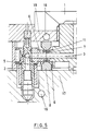
- the hot runner distributor shown in FIG. 1 is arranged between a central connecting piece 1 of an extruder (not shown) and a plurality of hot runner nozzles 2, only one of the hot runner nozzles 2 being shown in FIG. 1.
- the hot runner distributor serves to guide the plastic melt supplied by the extruder through a melt channel 3 kept at the predetermined temperature to the hot runner nozzles 2, which inject the plastic melt into a mold.
- the hot runner manifold has electrically heated sections 4, which are each connected to the connected hot runner nozzles 2 by a pipe plug connection 5.
- a corresponding pipe connector 5 is also arranged at the transition between the connector 1 of the extruder and the hot runner manifold.
- Corresponding pipe plug connections 5 can also be provided between individual sections 4 of the hot runner distributor which are aligned with one another.
- Each of the pipe plug connections 5 has two pipe ends 6 which are aligned with one another and surround the melt channel 3. These pipe ends 6 are either soldered in, shrunk in, or designed as a fixed component in the adjacent sections of the hot runner manifold or hot runner nozzle 2.
- each pipe connector 5 The two pipe ends 6 of each pipe connector 5 are separated from one another by an expansion joint 7.
- the width of the expansion joint 7 changes with thermal expansion within the hot runner manifold.
- the two pipe ends 6 are enclosed by a common cooling ring 8.
- the cooling ring 8 is provided on its outer circumference with cooling fins 9 which are cooled by the surrounding air.
- a cooling fan (not shown) can be provided.
- the cooling ring 8 has a cooling channel 10 through which a cooling medium, preferably cooling liquid, flows.
- the two pipe ends 6 each have a circumferential end groove in their two end faces facing the expansion joint 7 11, which extends into the tube end 6 in the axial direction.
- a common insulating ring 12 is accommodated in the two mutually facing end grooves 11, which is made of a good heat-insulating material, preferably metal.
- the insulating ring 12 has a circumferential collar 13 on its inner and outer circumference, which is arranged in the parting line 7 and prevents longitudinal displacement of the insulating ring 12.
- the cooling ring 8 consists of cast material, for example an aluminum alloy.
- Fig. 2 shows that the cooling ring 8 consists of two interconnected, substantially semicircular ring half-shells 8a and 8b, which are connected to one another by screw connections 14 to form a ring clamp.
- cooling ring 8 has a wear-resistant, hard inner shell 15 made of hardened steel on its bore wall surrounding the pipe ends 6.
- the insulating ring 12 inserted into the expansion joint 7 can also be dispensed with on the pipe plug connection.
- the partially solidifying plastic melt penetrating into the expansion joint 7 and into the end grooves 11 forms an insulating ring between the two pipe ends 6 facing each other.
- the pipe ends 6 are made in one piece with the subsequent sections.
- the cooling ring 8 lies at the bottom on one through cooling channels 16 cooled tool plate 17 and on top of a counter pressure plate 19 cooled by cooling channels 18.
- the plug connection 5 is cooled by dissipating the heat from the cooling ring 8 into the cooled plates 17 and 19.
Landscapes
- Engineering & Computer Science (AREA)
- Manufacturing & Machinery (AREA)
- Mechanical Engineering (AREA)
- Moulds For Moulding Plastics Or The Like (AREA)
- Variable-Direction Aerials And Aerial Arrays (AREA)
- Recrystallisation Techniques (AREA)
- Amplifiers (AREA)
Claims (10)
- Distributeur à canaux chauffants pour acheminer une masse fondue de matière thermoplastique synthétique par un canal (3) à des buses (2) de canaux chauffants sur des outils de formage, ledit distributeur comprenant des raccords d'enfichage tubulaires (5) entre des sections du distributeur à canaux chauffants et des pièces de jonction voisines, caractérisé en ce que les raccords d'enfichage tubulaires (5) présentent respectivement deux bouts de tube (6) alignés l'un sur l'autre et enserrant le canal (3) acheminant la masse fondue, lesdits bouts de tube (6) étant séparés l'un de l'autre par un joint de dilatation (7), et en ce que les deux bouts de tube (6) sont enserrés par un anneau de refroidissement commun (8) dans la zone de leur joint de dilatation (7).
- Distributeur à canaux chauffants selon la revendication 1, caractérisé en ce que les deux bouts de tube (6) présentent, dans leurs deux faces frontales tournées vers le joint de dilatation (7), respectivement une rainure frontale (11) périphérique s'étendant axialement.
- Distributeur à canaux chauffants selon la revendication 2, caractérisé en ce qu'une bague isolante commune (12) est reçue dans les deux rainures frontales (11) tournées l'une vers l'autre.
- Distributeur à canaux chauffants selon la revendication 3, caractérisé en ce que la bague isolante (12) présente, sur sa périphérie intérieure et/ou extérieure, une arête périphérique (13) agencée dans le joint de dilatation (7).
- Distributeur à canaux chauffants selon la revendication 4, caractérisé en ce que la bague isolante (12) est constituée d'un matériau thermo-isolant.
- Distributeur à canaux chauffants selon la revendication 1, caractérisé en ce que l'anneau de refroidissement (8) est équipé, sur sa périphérie extérieure, de nervures de refroidissement (9).
- Distributeur à canaux chauffants selon la revendication 1, caractérisé en ce que l'anneau de refroidissement (8) présente un canal de refroidissement (10) parcouru par un réfrigérant.
- Distributeur à canaux chauffants selon la revendication 1, caractérisé en ce que l'anneau de refroidissement (8) s'applique sur des plaques refroidies (17, 19).
- Distributeur à canaux chauffants selon l'une quelconque des revendications 1 à 8, caractérisé en ce que l'anneau de refroidissement (8) est constitué de deux demi-coques annulaires (8a, 8b) raccordées l'une à l'autre.
- Distributeur à canaux chauffants selon l'une quelconque des revendications 1 à 9, caractérisé en ce que l'anneau de refroidissement (8) présente, sur sa paroi tubulaire enserrant les bouts de tube (6), une coque intérieure dure résistant à l'usure.
Applications Claiming Priority (3)
| Application Number | Priority Date | Filing Date | Title |
|---|---|---|---|
| DE4320584A DE4320584A1 (de) | 1993-06-22 | 1993-06-22 | Heißkanalverteiler |
| DE4320584 | 1993-06-22 | ||
| PCT/EP1994/001929 WO1995000312A1 (fr) | 1993-06-22 | 1994-06-13 | Distributeur a canaux chauffants |
Publications (2)
| Publication Number | Publication Date |
|---|---|
| EP0706447A1 EP0706447A1 (fr) | 1996-04-17 |
| EP0706447B1 true EP0706447B1 (fr) | 1997-05-14 |
Family
ID=6490860
Family Applications (1)
| Application Number | Title | Priority Date | Filing Date |
|---|---|---|---|
| EP94920932A Expired - Lifetime EP0706447B1 (fr) | 1993-06-22 | 1994-06-13 | Distributeur a canaux chauffants |
Country Status (4)
| Country | Link |
|---|---|
| EP (1) | EP0706447B1 (fr) |
| AT (1) | ATE152959T1 (fr) |
| DE (2) | DE4320584A1 (fr) |
| WO (1) | WO1995000312A1 (fr) |
Cited By (1)
| Publication number | Priority date | Publication date | Assignee | Title |
|---|---|---|---|---|
| WO2008017142A1 (fr) * | 2006-08-11 | 2008-02-14 | Husky Injection Molding Systems Ltd. | Joint d'étanchéité d'un ensemble cylindre |
Families Citing this family (12)
| Publication number | Priority date | Publication date | Assignee | Title |
|---|---|---|---|---|
| DE19603947C2 (de) * | 1996-02-05 | 1999-02-11 | Incoe Inernational Inc | Heißkanal-Verteilersystem für Spritzgießanlagen |
| CA2180603A1 (fr) * | 1996-07-05 | 1998-01-06 | Jobst Ulrich Gellert | Rampes de buses pour moulage par injection et raccord |
| CA2205978C (fr) * | 1997-05-23 | 2005-01-18 | Jobst Ulrich Gellert | Manchon de raccordement de collecteurs de moulage par injection |
| DE19821406A1 (de) * | 1998-05-13 | 1999-11-18 | Lurgi Zimmer Ag | Abdichtungselement für Schmelzekanäle |
| NL1012925C2 (nl) | 1999-08-27 | 2001-02-28 | Franciscus Antonius Jozef Van | Spuitgietinrichting. |
| US6675055B1 (en) | 2000-06-16 | 2004-01-06 | Mold Masters Ltd. | Method and apparatus for an automated injection molding configuring and manufacturing system |
| US7105123B2 (en) | 2003-02-20 | 2006-09-12 | Mold-Masters Limited | Heat dissipation device for and method of dissipating heat from a manifold |
| DE102004015033A1 (de) | 2003-03-31 | 2004-11-25 | Mold-Masters Ltd., Georgetown | Guss-Heißläuferverteiler für Spritzgießvorrichtungen |
| US20080199554A1 (en) * | 2004-05-17 | 2008-08-21 | Husky Injection Molding Systems Ltd. | Method and apparatus for coupling melt conduits in a molding system and/or a runner system |
| US7517208B2 (en) | 2006-10-12 | 2009-04-14 | Husky Injection Molding Systems Ltd. | Injection molding system having a cooperating tapered machine nozzle and barrel head |
| US7575428B2 (en) | 2006-10-12 | 2009-08-18 | Husky Injection Molding Systems Ltd. | Molding system including body overlapping and sealing conduits, amongst other things |
| ITBI20070014A1 (it) * | 2007-10-23 | 2009-04-24 | Thermoplay Spa | Piastra di distribuzione perfezionata per uno stampo per lo stampaggio ad iniezione di materiali plastici |
Family Cites Families (5)
| Publication number | Priority date | Publication date | Assignee | Title |
|---|---|---|---|---|
| US3553788A (en) * | 1968-09-10 | 1971-01-12 | Ladislao Wladyslaw Putkowski | Hot runner system for plastic injection molds |
| JPS51136742A (en) * | 1975-05-21 | 1976-11-26 | Fuji Plastics | Runnerless mold of hot runner type |
| US4219323A (en) * | 1979-05-09 | 1980-08-26 | The Broadway Companies, Inc. | Self-compensating hot manifold link |
| SE434482B (sv) * | 1981-05-07 | 1984-07-30 | Dante Luigi Alfonsi | Varmkanalsystem vid en maskin for formsprutning av plast |
| US4497624A (en) * | 1982-11-08 | 1985-02-05 | Electra Form, Inc. | Injection molding machine |
-
1993
- 1993-06-22 DE DE4320584A patent/DE4320584A1/de not_active Withdrawn
-
1994
- 1994-06-13 DE DE59402766T patent/DE59402766D1/de not_active Expired - Fee Related
- 1994-06-13 AT AT94920932T patent/ATE152959T1/de not_active IP Right Cessation
- 1994-06-13 WO PCT/EP1994/001929 patent/WO1995000312A1/fr not_active Ceased
- 1994-06-13 EP EP94920932A patent/EP0706447B1/fr not_active Expired - Lifetime
Cited By (1)
| Publication number | Priority date | Publication date | Assignee | Title |
|---|---|---|---|---|
| WO2008017142A1 (fr) * | 2006-08-11 | 2008-02-14 | Husky Injection Molding Systems Ltd. | Joint d'étanchéité d'un ensemble cylindre |
Also Published As
| Publication number | Publication date |
|---|---|
| DE59402766D1 (de) | 1997-06-19 |
| DE4320584A1 (de) | 1995-01-05 |
| ATE152959T1 (de) | 1997-05-15 |
| EP0706447A1 (fr) | 1996-04-17 |
| WO1995000312A1 (fr) | 1995-01-05 |
Similar Documents
| Publication | Publication Date | Title |
|---|---|---|
| EP0706447B1 (fr) | Distributeur a canaux chauffants | |
| DE69311247T2 (de) | Abgedichtete, seitliche Angussöffnung | |
| DE69912485T2 (de) | Gekühlter Spritzgiesseinsatz | |
| DE10392533B4 (de) | Spritzgießvorrichtung mit einem Formangussöffnungseinsatz mit Wärmesperre | |
| DE3403301C2 (fr) | ||
| DE69520807T2 (de) | Spritzgiessdüse mit schraubenförmiger Kühlleitung | |
| EP0781640B1 (fr) | Buse obturatrice à aiguille chauffée | |
| DE19521733B4 (de) | Einteiliger Druckgußeinsatz mit einer mit radialen Rippen versehenen Kühlkammer | |
| EP0445313B1 (fr) | Distributeur | |
| DE2356764B2 (de) | Heißkanal-Spritzgießwerkzeug mit mehreren Formhohlräumen | |
| DE4137664B4 (de) | Spritzgießvorrichtung mit gesondertem Heizelement im den Formhohlraum bildenden Einsatz | |
| DE3424569A1 (de) | Beheizter verteilerkopf an spritzgussformen fuer kunststoffe | |
| DE2657551C3 (de) | Vorrichtung zur Herstellung von Guß mit gerichtetem Gefuge | |
| DE202010017853U1 (de) | Dichtungsanordnung für eine Seitenangussdüse in einem Spritzgießsystem | |
| DE102004001665B4 (de) | Spritzgießvorrichtung mit einer verlängerten Düse, die mehrere Düsenkörper in Tandemanordnung umfasst, und Verwendung einer Düse | |
| DE69311917T2 (de) | Spritzgiessvorrichtung | |
| DE69504330T2 (de) | Abstandeinstellung von einem strömungskanal in einer vorrichtung zum formen von kunststoffteilen | |
| WO2010003473A2 (fr) | Buse d'injection pour moule d'injection | |
| DE69913378T2 (de) | Spritzgiesskühlungskern mit rippenkappe | |
| DE69603537T2 (de) | Heisse seitliche Spritzgiessanschnittabdichtung mit Umfangsrand | |
| EP4045267B1 (fr) | Outil de moulage par injection | |
| DE3338783C1 (de) | Spritzgießform zur Herstellung von Formartikeln aus wärmehärtbaren Werkstoffen | |
| EP2633971B1 (fr) | Buse de moulage par injection avec des aiguilles d'obturation guidées par manchon de guidage et dispositif de moulage ainsi équipé | |
| EP0936965B1 (fr) | Filiere de moulage par injection | |
| DE19802387A1 (de) | Druckgußvorrichtung mit gekühltem Kern |
Legal Events
| Date | Code | Title | Description |
|---|---|---|---|
| PUAI | Public reference made under article 153(3) epc to a published international application that has entered the european phase |
Free format text: ORIGINAL CODE: 0009012 |
|
| 17P | Request for examination filed |
Effective date: 19960118 |
|
| AK | Designated contracting states |
Kind code of ref document: A1 Designated state(s): AT CH DE ES FR GB IT LI PT |
|
| GRAG | Despatch of communication of intention to grant |
Free format text: ORIGINAL CODE: EPIDOS AGRA |
|
| 17Q | First examination report despatched |
Effective date: 19960802 |
|
| GRAH | Despatch of communication of intention to grant a patent |
Free format text: ORIGINAL CODE: EPIDOS IGRA |
|
| GRAH | Despatch of communication of intention to grant a patent |
Free format text: ORIGINAL CODE: EPIDOS IGRA |
|
| GRAA | (expected) grant |
Free format text: ORIGINAL CODE: 0009210 |
|
| AK | Designated contracting states |
Kind code of ref document: B1 Designated state(s): AT CH DE ES FR GB IT LI PT |
|
| PG25 | Lapsed in a contracting state [announced via postgrant information from national office to epo] |
Ref country code: IT Free format text: LAPSE BECAUSE OF FAILURE TO SUBMIT A TRANSLATION OF THE DESCRIPTION OR TO PAY THE FEE WITHIN THE PRE;WARNING: LAPSES OF ITALIAN PATENTS WITH EFFECTIVE DATE BEFORE 2007 MAY HAVE OCCURRED AT ANY TIME BEFORE 2007. THE CORRECT EFFECTIVE DATE MAY BE DIFFERENT FROM THE ONE RECORDED.SCRIBED TIME-LIMIT Effective date: 19970514 Ref country code: GB Effective date: 19970514 Ref country code: FR Effective date: 19970514 Ref country code: ES Free format text: THE PATENT HAS BEEN ANNULLED BY A DECISION OF A NATIONAL AUTHORITY Effective date: 19970514 |
|
| REF | Corresponds to: |
Ref document number: 152959 Country of ref document: AT Date of ref document: 19970515 Kind code of ref document: T |
|
| REG | Reference to a national code |
Ref country code: CH Ref legal event code: EP |
|
| REF | Corresponds to: |
Ref document number: 59402766 Country of ref document: DE Date of ref document: 19970619 |
|
| PG25 | Lapsed in a contracting state [announced via postgrant information from national office to epo] |
Ref country code: PT Effective date: 19970814 |
|
| EN | Fr: translation not filed | ||
| GBV | Gb: ep patent (uk) treated as always having been void in accordance with gb section 77(7)/1977 [no translation filed] |
Effective date: 19970514 |
|
| PLBE | No opposition filed within time limit |
Free format text: ORIGINAL CODE: 0009261 |
|
| STAA | Information on the status of an ep patent application or granted ep patent |
Free format text: STATUS: NO OPPOSITION FILED WITHIN TIME LIMIT |
|
| 26N | No opposition filed | ||
| PGFP | Annual fee paid to national office [announced via postgrant information from national office to epo] |
Ref country code: AT Payment date: 20000615 Year of fee payment: 7 |
|
| PGFP | Annual fee paid to national office [announced via postgrant information from national office to epo] |
Ref country code: DE Payment date: 20000705 Year of fee payment: 7 |
|
| PG25 | Lapsed in a contracting state [announced via postgrant information from national office to epo] |
Ref country code: AT Free format text: LAPSE BECAUSE OF NON-PAYMENT OF DUE FEES Effective date: 20010613 |
|
| PG25 | Lapsed in a contracting state [announced via postgrant information from national office to epo] |
Ref country code: DE Free format text: LAPSE BECAUSE OF NON-PAYMENT OF DUE FEES Effective date: 20020403 |
|
| PGFP | Annual fee paid to national office [announced via postgrant information from national office to epo] |
Ref country code: CH Payment date: 20020725 Year of fee payment: 9 |
|
| PG25 | Lapsed in a contracting state [announced via postgrant information from national office to epo] |
Ref country code: LI Free format text: LAPSE BECAUSE OF NON-PAYMENT OF DUE FEES Effective date: 20030630 Ref country code: CH Free format text: LAPSE BECAUSE OF NON-PAYMENT OF DUE FEES Effective date: 20030630 |
|
| REG | Reference to a national code |
Ref country code: CH Ref legal event code: PL |