EP0706621B1 - A vibration-compensating apparatus for counteracting vibrations - Google Patents
A vibration-compensating apparatus for counteracting vibrations Download PDFInfo
- Publication number
- EP0706621B1 EP0706621B1 EP94920421A EP94920421A EP0706621B1 EP 0706621 B1 EP0706621 B1 EP 0706621B1 EP 94920421 A EP94920421 A EP 94920421A EP 94920421 A EP94920421 A EP 94920421A EP 0706621 B1 EP0706621 B1 EP 0706621B1
- Authority
- EP
- European Patent Office
- Prior art keywords
- rotary body
- shaft
- shafts
- vibration
- body part
- Prior art date
- Legal status (The legal status is an assumption and is not a legal conclusion. Google has not performed a legal analysis and makes no representation as to the accuracy of the status listed.)
- Expired - Lifetime
Links
- 230000005540 biological transmission Effects 0.000 claims abstract description 12
- 230000005284 excitation Effects 0.000 claims abstract description 12
- 230000005484 gravity Effects 0.000 claims description 12
- 230000008878 coupling Effects 0.000 claims description 11
- 238000010168 coupling process Methods 0.000 claims description 11
- 238000005859 coupling reaction Methods 0.000 claims description 11
- 238000005192 partition Methods 0.000 description 11
- 239000003921 oil Substances 0.000 description 9
- 239000012530 fluid Substances 0.000 description 6
- 238000005259 measurement Methods 0.000 description 2
- 238000000034 method Methods 0.000 description 2
- 238000007789 sealing Methods 0.000 description 2
- 125000004122 cyclic group Chemical group 0.000 description 1
- 230000009977 dual effect Effects 0.000 description 1
- 230000001050 lubricating effect Effects 0.000 description 1
- 239000010687 lubricating oil Substances 0.000 description 1
- 238000005461 lubrication Methods 0.000 description 1
- 230000001105 regulatory effect Effects 0.000 description 1
- 230000000717 retained effect Effects 0.000 description 1
- 230000007704 transition Effects 0.000 description 1
Images


Classifications
-
- F—MECHANICAL ENGINEERING; LIGHTING; HEATING; WEAPONS; BLASTING
- F16—ENGINEERING ELEMENTS AND UNITS; GENERAL MEASURES FOR PRODUCING AND MAINTAINING EFFECTIVE FUNCTIONING OF MACHINES OR INSTALLATIONS; THERMAL INSULATION IN GENERAL
- F16F—SPRINGS; SHOCK-ABSORBERS; MEANS FOR DAMPING VIBRATION
- F16F15/00—Suppression of vibrations in systems; Means or arrangements for avoiding or reducing out-of-balance forces, e.g. due to motion
- F16F15/22—Compensation of inertia forces
Definitions
- vibration-compensating apparatus It is known to compensate the unbalanced moments of the first, second and/or higher order from marine engines by means of a vibration-compensating apparatus. It is furthermore known that such vibration-compensating apparatus also may be used to compensate for other unbalanced forces or moments, for instance from the propellers.
- DK-B 155.544 discloses a vibration-compensating apparatus comprising two rotary bodies fixedly mounted on individual vertical shafts arranged mutually parallel. Adjustment of the resulting oscillating force is made by supplying or removing mass from each of the two rotary bodies, which is a quite time-consuming operation.
- DK-B-169848 discloses a vibration-compensating apparatus for counteracting unbalanced moments and thereby vibrations generated by an excitation source, such as the main engine of a vessel, and comprising two horizontal shafts arranged parallel in a housing, a rotary body with the same eccentric mass being mounted on each of said shafts, each of said bodies comprising a rotary body part fixedly mounted on the shaft and rotary body part mounted on the shaft releasable for turning, said shafts being interconnected through a transmission so as to rotate in opposite directions and driven synchronously at a rpm being a multiple of the rpm of the excitation source by means of a driving motor for the vibration-compensating apparatus, said motor being controlled by a control and synchronising device.
- the object of the present invention is to provide a compact and simple vibration-compensating apparatus of the type stated in the introduction, which easy to adjust as regards the size and the direction of the resulting oscillating force.
- this is achieved by arranging the apparatus in such a position that the rotary body shafts are arranged essentially vertically according to claim 1.
- a compact vibration-compensating apparatus is provided, which can be very easily constructed, as a fairly simple transmission can be used to drive the two rotary bodies in opposite directions so as to generate a resulting force component equal to zero in one direction and in a direction perpendicular thereto a resulting force harmonically varying between zero and twice the force of the eccentric mass of each rotary body.
- very little force is needed to alter the position of the releasable rotary body parts relative to the fixed rotary body parts, the unbalanced masses remaining in the same horizontal plane. In practice, it has proved possible to carried out this mutual turning of the rotary body parts of a rotary body manually.
- each shaft may at its upper end be provided with a marking for indicating the position of the centre of gravity of the fixed rotary body part. Consequently, it is possible to observe the position of the fixed rotary body parts of the two rotary bodies, which is very advantageous in connection with adjusting the direction of the harmonically oscillating force.
- a releasable coupling in the transmission between the two shafts, may be provided allowing one rotary body to turn relative to the other. By turning the two rotary bodies relative to each other, the direction of the harmonically oscillating force is altered.
- An easily releasable coupling in the transmission between the two shafts simplifies the adjustment of the force direction.
- the easily releasable coupling may for instance by the shaft/ hub coupling between a gear wheel and the shaft and may be formed of a releasable interference fit, which e.g. may be provided by means of a cone connection formed as a bush, for instance a Taperlock tm bush or a Ringfeder tm bush.
- one of the rotary body parts of each rotary body may be provided with a graduated scale and the other with a indication line arranged on adjacent portions of the rotary body parts. The position of the rotary body parts of each rotary body may then be read and controlled directly, which facilitates an accurate setting of the rotary body parts of the rotary bodies relative to each other.
- the graduated scale may advantageously be arranged on the periphery of the fixed rotary body part opposite the centre of gravity, and an opening may be provided in the wall of the housing, through which the graduated scale and the indication line may be seen.
- one of the rotary body shafts may be a hollow shaft coaxially arranged on the second shaft, whereby a very compact embodiment of the invention is obtained.
- the vibration-compensating apparatus may further comprise a gear wheel mounted on the hollow shaft and engaging a gear wheel mounted on a pivotal countershaft arranged parallel to the hollow shaft, and a drive connection connected with the driving motor and rotating the second central shaft and the countershaft in the same direction and at the same rpm.
- the drive connection comprises a first pulley mounted on the free end of the inner shaft, a corresponding second pulley mounted on the free end of countershaft, a third pulley mounted on an output shaft of the driving motor, and a belt connecting about three mentioned pulleys.
- the shafts may be offset relative to each other and the transmission therebetween may comprise two gear wheels in mutual engagement and each mounted on one of the shafts.
- the releasable coupling may be formed of a releasable shaft/hub coupling between at least one of the shafts and one of the gear wheels.
- the releasable coupling may be of any known type which enables a quick change of the relative position between the gear wheel and the shaft.
- the centres of gravity of the two rotary bodies may be arranged in the mutual plane of the shafts, when the resulting force of the vibration-compensating apparatus equals zero.
- the centres of gravity of the rotary bodies are arranged in such a manner that the resulting force in the mutual shaft plane equal zero, while the harmonically oscillating force is perpendicular thereto.
- This embodiment or setting of the rotary bodies is preferable due to the moment.
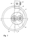
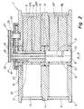
- Figs. 1 and 2 show a vibration-compensating apparatus comprising a housing 1 having a first end wall 2, a second end wall 3 and a partition wall 4. Between the first end wall 2 and the partition wall 4 a first circumferential wall 5 is arranged. In a corresponding manner a second circumferential wall 6 is arranged between the partition wall 4 and the end wall 3.
- the housing 1 is assembled by staybolts (not shown) extending in between the two end walls 2,3.
- the second end wall 3 forms the base of the housing and is provided with mounting holes (not shown).
- a dual shaft comprising an inner central shaft 8 and a hollow shaft 9 arranged pivotally thereon is supported by the end walls 2 and 3 and the partition wall 4 by means of bearings.
- the central shaft comprises a first shaft portion 10 of a larger diameter and a second shaft portion 11 of a smaller diameter.
- the hollow shaft 9 is arranged on the small shaft portion 11 of the central shaft 8 and has the same outer diameter as the first shaft portion 10 of the central shaft 8.
- the large shaft portion 10 of the central shaft 8 is pivotally arranged relative to the other end wall 3 by means of a bearing 13.
- the first shaft portion of the central shaft 8 is pivotally arranged in the partition wall 4 by means of a bearing 14.
- the hollow shaft 9 is at its lower end pivotally arranged relative to the partition wall 4 by means of a bearing 15, and at its upper end pivotally arranged relative to the upper end wall 2 by means of a bearing 16.
- the hollow shaft is pivotally arranged by means of a bearing 18 on the small shaft portion 11 of the central shaft.
- a rotary body 19 is arranged and being essentially shaped like the sector of a circle when seen in axial direction and thus having an eccentric centre of gravity.
- the rotary body 19 comprises a rotary body part 19F being fixedly mounted on the large shaft portion 10 of the shaft 8 and a releasably arranged rotary body part 19L being releasable for turning relative to the fixed rotary body part 19F.
- a rotary body 20 is mounted on the hollow shaft, said body also being shaped like sector of a circle when seen in an axial direction and comprising a rotary body part 20F being fixedly mounted on the shaft and a releasably arranged rotary body part 20L.
- the releasably arranged rotary body parts 19L, 20L may be released and turned by supplying pressurised fluid to the mounting area between the shaft and the rotary body part, for instance as disclosed in Danish patent publication DK-B-169 848.
- the two shafts 8, 9 are interconnected through a transmission so as to rotate in opposite directions.
- the transmission comprises a first gear wheel 23 fixed to the hollow shaft 9 at the upper end 17 thereof, and an engaging second gear wheel 24 mounted on a shaft 25.
- a pulley 26 is mounted on the outer end of the small shaft portion 11 of the central shaft 8.
- a corresponding pulley 27 is mounted on the outer end of the second shaft 25.
- a third pulley 28 is mounted on the output shaft of a driving motor 29, preferably a servomotor, driving the two pulleys 26,27 in the same direction via a belt 30, whereby the central shaft 8 and the hollow shaft 9 and consequently also the rotary bodies 19,20 connected thereto rotate in opposite directions.
- a driving motor 29 preferably a servomotor
- the releasable rotary body part 19L,20L of the rotary bodies may be turned relative to the fixed rotary body part 19F, 20F, the force generated by each rotary body may be regulated and the resulting force component may thereby be adjusted continuously from zero to four time the force of each rotary body part, when said parts have an equal eccentric mass.
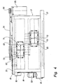
- Figs. 3, 4, and 5 illustrate a preferred embodiment of a vibration-compensating apparatus according to the invention comprising a housing 31 having an upper wall 32, a lower wall 33 and a partition wall 34. Furthermore, the housing has a circumferential wall 35.
- the upper wall 32 is fixed to the circumferential wall 35 by means of screws 36.
- the lower wall 33 is fixed to the circumferential wall 35 by means of screws 37.
- the upper wall 32 is provided with an opening 61 closable by means of a cover 62.
- the circumferential wall 35 is provided with an upper opening 63 to an upper chamber 64 formed between the upper wall 32 and the partition wall 34, and a lower opening 65 to a lower chamber 66 formed between the partition wall 34 and the lower wall 33.
- the upper and lower opening 63,65 may also be closed by means of covers (not shown) which are attached to the circumferential wall by means of screw.
- the lower wall 33 is provided with an outer depression covered by means of a bottom cover 67 to define a oil chamber 68.
- the bottom cover 67 is fixed to the lower wall 33 by means of screws 69.
- mounting holes 40 are provided in the lower wall for bolting the vibration-compensating apparatus to a foundation.
- a lower shaft 38 is pivotally arranged by means of a lower bearing 43 in the lower wall 33 and an upper bearing 44 in the partition wall 34.
- a rotary body 49 is mounted on the lower shaft 38, said body being shaped essentially like the sector of a circle when seen in axial direction, and thus having an eccentric centre of gravity.
- the rotary body 49 comprises a rotary body part 49F fixedly mounted on the lower shaft and a releasably mounted rotary body part 49L being releasable for turning relative to the fixed rotary body part 49F.
- an upper shaft 39 is arranged by means of a lower bearing 45 arranged in the partition wall 34 and an upper bearing 46 arranged in the upper wall 32.
- a rotary body part 50F is likewise fixedly mounted and a releasably mounted rotary body part 50L being releasable for turning relative to the fixed rotary body part 50F.
- the releasably arranged rotary body parts 49L, 50L may be released and turned relative to the fixed rotary body parts 49F, 50F by supplying pressurised fluid through passages 51,52 to the mounting area between the shaft and the rotary body part, as described in connection with the first embodiment of the invention.
- a first threaded hole 47 is provided in the circumferential wall 35, said hole extending into the lower chamber 66 on the level with the releasable rotary body part 49L.
- a second threaded hole 48 is provided in circumferential wall 35, said hole extending into the upper chamber 64 on the level with the upper releasable rotary body part 50L.
- a screw may be screwed into the threaded holes 47,48 to engage the rotary body part 49L, 50L in question in order to retain said part during turning of the other rotary body parts, pressurised fluid being supplied to the passages 51,52, respectively at the same time.
- the two shafts are interconnected so as to rotate in opposite directions by means of two gear wheels 53,54 in mutual engagement and arranged in the lower chamber 66.
- the first gear wheel 53 is releasably arranged at the lower shaft between the bearing 44 and the releasable rotary body part 49L.
- the releasable gear wheel 53 may be released for turning by supplying pressurised fluid via a passage 41 to its mounting area on the shaft 38 in a manner corresponding to the manner in which the releasable rotary body parts 49L,50L are released.
- the releasable gear wheel 53 may, however, be mounted by means of a great number of releasable shaft/hub coupling, such as a so-called Ring-feder tm bush or another connecting means which allows a fast release of the connection between the shaft and the gear wheel mounted thereon.
- the second gear wheel 54 is fixedly mounted on an end portion of the upper shaft 39 extending into the lower chamber 66.
- each of the fixed rotary body parts 49F,50F is provided with a graduated scale 70,71 (confer Fig. 4).
- each of the releasable rotary body parts 40L,50L is provided with a indication line 72,73 on the periphery opposite the centre of gravity C F .
- the graduated scale 70,71 extend over 180° and may as the indication line 72,73 be seen through the lower and upper opening 65,63, respectively, in the circumferential wall 35.
- the indication lines 72,73 and the related graduated scales 70,71 are intended to ensure that the rotary body parts of the rotary bodies 49, 50 are arranged correctly relative to each other.
- the two shafts 38,39 are provided with an indication marking 75,76 arranged on the radius of the centre of gravity C F of the fixed rotary body part 49F, 50F, confer Fig. 5. As it will appear from below, these indications marks are used, when the direction of the resulting force generated by the vibration-compensating apparatus is to be altered.
- the upper shaft 39 comprises an upper shaft end 79, extending through the upper wall 32, and a sealing over 80 fixed to the upper wall 32.
- a passage is provided in the sealing cover 80 for supplying lubricating oil to the vibration-compensating apparatus.
- the oil supplied is accumulated in the oil chamber 68 and fed back to the inlet passage via an outlet passage 82 in the lower wall 33 and an oil line 81.
- An oil filter 92 and oil pump 93 are provided in the oil duct.
- the lubricating system ensures an effective lubrication of the bearings of the vibration-compensating apparatus and by means of the oil chamber 68 it is obtained that the lower bearing 43 may be drained so it is not submerged in oil.
- a pulley 83 is mounted, by means of which the vibration-compensating apparatus is driven via a belt 84 and a motor 95, a pulley 96 being mounted on the output shaft thereof.
- a sensor 84 is provided in the upper wall 32 sensing the passage of a screw head 85 of a screw screwed into the releasable rotary body part 50L of the upper rotary body.
- the sensor 84 serves to continuously register a point of reference for the cyclic movement of the vibration-compensating apparatus.
- the phase angle between the excitation source, for which the apparatus is to compensate, and a point of reference on the cycle of the engine 86 are measured or estimated.
- the reference point of the engine 86 may typically be the top dead-centre of the first cylinder measured on the main shaft 87.
- the position and the speed of the reference point is registered continuously by the synchronising device 88 by means of a position sensor 89 and a pulse train sensor 90.
- the signals measured on the main shaft 86 is compared to a position measurement made by means of the sensor 84 in the housing 31 and a velocity measurement of the driving motor 91 of the vibration-compensating apparatus.
- the synchronising device 88 may be adjusted in such a manner that the force from the vibration-compensating apparatus is in antiphase and varies synchronously with the excitation source.
- the phase is the same, whether the vibration-compensating apparatus is active or inactive, but the size of the vibration amplitude is of course reduced, when the vibration-compensating apparatus is active.
- the size of the force is determined by employing the vibration-compensating apparatus as an oscillator or exciter when the engine of the vessel is stopped and vice versa. Based thereon, the vibration-compensating apparatus is adjusted to the force giving the same amplitude as the excitation source present at the given place on the vessel.
- the force of the vibration-compensating apparatus is adjusted by turning the two fixed rotary body parts 49F, 50F relative to the releasable rotary body parts 49L, 50L, the parts being turned in opposite directions, confer Fig. 5. Subsequent to the adjustment, the resulting force F is the sum of the two forces F L , F F from a fixed and from a releasable rotary body part 49F, 49L; 50F, 50L acting on a line of application at haft the angle ⁇ /2 of the angle ⁇ over which the two rotary body parts 49F, 50F have been turned relative to each other.
- the method of adjustment is initially to retain one of the releasable rotary body parts, for instance 49L, by screwing a screw into the threaded hole 47 to engage the releasable rotary body part 49L and subsequently to supply pressurised fluid via the passage 51 in the shaft 38 to the mounting area between the rotary body part 49F and the shaft.
- the three other rotary body parts may be turned to a new position.
- the method is then used to change the position of the upper releasable rotary body part 50L relative to the other rotary body parts.
- the two fixed rotary body parts 49F, 50F are turned equally relative to the releasable rotary body parts 49L, 50L.
- the graduated scale 70,71 on the fixed rotary body parts and the indication lines 72,73 on the releasable rotary body parts can be used for this purpose.
- the releasable body parts 49L, 50L is retained in a position, in which said graduated scales and marking lines can be seen through the openings 63,65 in the circumferential wall 35 of the housing 31.
- the phase angle in the synchronising device 88 is changed by haft the yaw angle ⁇ /2. Furthermore, after adjusting the force size, the phase angle in the synchronising device is changed in accordance with the angle, over which the releasable rotary body part 50L has been turned at the change of the force size, i.e. the angle over which the screw head 85 for the position sensor 84 has been turned.
- the direction of the harmonically varying force of the vibration-compensating apparatus is determined by the relative position between the two fixed rotary body parts 49F, 50F.
- a marking 75,76 is provided on the upwardly facing shaft end faces 77,78, said marking indicating the line of application of the force of the fixed rotary body part relative to the shaft.
- the shaft end face 77 of the lower shaft can be seen through the opening 61.
- the releasable connection between the lower shaft 38 and the gear wheel 53 makes it possible to adjust the force direction of the oscillating force arbitrarily by turning the lowermost shaft 39 to the desired force direction, loosen the connection between the shaft 38 and the gear wheel 53 by supplying pressurised fluid to the passage 41, and by turning the fixed rotary body part 50F on the upper shaft 39 until the indication marking 76 on the shaft end face 78 thereof has the same direction as the indication marking 75 on the shaft end face 77 of the lower shaft 38.
- the phase angle in the synchronising device is changed to correspond to the angle to which the upper releasable rotary body part 50L has been turned at the change of the force direction, i.e. the angle over which the screw head 85 for the position sensor 84 has been turned.
- the vibration-compensating apparatus When the force direction has been determined, it may be advantageous due to the inner moment in the vibration-compensating apparatus to turn the rotary bodies in such a manner that the harmonically varying force of the vibration-compensating apparatus is perpendicular to the mutual plane of the shafts and correspondingly to turn the entire vibration-compensating apparatus on the foundation in such a manner that the force is active in the direction just determined.
Landscapes
- Engineering & Computer Science (AREA)
- General Engineering & Computer Science (AREA)
- Physics & Mathematics (AREA)
- Acoustics & Sound (AREA)
- Aviation & Aerospace Engineering (AREA)
- Mechanical Engineering (AREA)
- Vibration Prevention Devices (AREA)
- Apparatuses For Generation Of Mechanical Vibrations (AREA)
- Connection Of Motors, Electrical Generators, Mechanical Devices, And The Like (AREA)
Priority Applications (1)
| Application Number | Priority Date | Filing Date | Title |
|---|---|---|---|
| SI9430044T SI0706621T1 (en) | 1993-07-09 | 1994-07-08 | A vibration-compensating apparatus for counteracting vibrations |
Applications Claiming Priority (5)
| Application Number | Priority Date | Filing Date | Title |
|---|---|---|---|
| DK083493A DK171084B1 (da) | 1993-07-09 | 1993-07-09 | Svingningskompensator |
| DK834/93 | 1993-07-09 | ||
| DK119193A DK170999B1 (da) | 1993-07-09 | 1993-10-22 | Svingningskompensator til at modvirke vibrationer |
| DK1191/93 | 1993-10-22 | ||
| PCT/DK1994/000283 WO1995002133A1 (en) | 1993-07-09 | 1994-07-08 | A vibration-compensating apparatus for counteracting vibrations |
Publications (2)
| Publication Number | Publication Date |
|---|---|
| EP0706621A1 EP0706621A1 (en) | 1996-04-17 |
| EP0706621B1 true EP0706621B1 (en) | 1997-05-07 |
Family
ID=26064740
Family Applications (1)
| Application Number | Title | Priority Date | Filing Date |
|---|---|---|---|
| EP94920421A Expired - Lifetime EP0706621B1 (en) | 1993-07-09 | 1994-07-08 | A vibration-compensating apparatus for counteracting vibrations |
Country Status (9)
| Country | Link |
|---|---|
| EP (1) | EP0706621B1 (es) |
| JP (1) | JP3475404B2 (es) |
| KR (1) | KR100323279B1 (es) |
| CN (1) | CN1041549C (es) |
| AU (1) | AU7122394A (es) |
| DE (1) | DE69403079T2 (es) |
| DK (1) | DK170999B1 (es) |
| ES (1) | ES2101546T3 (es) |
| WO (1) | WO1995002133A1 (es) |
Families Citing this family (17)
| Publication number | Priority date | Publication date | Assignee | Title |
|---|---|---|---|---|
| DE69502200T2 (de) * | 1994-08-24 | 1998-08-13 | Smidth & Co As F L | Schwingungskompensierende vorrichtung |
| DE19613445C2 (de) * | 1996-04-04 | 2002-04-18 | Man B & W Diesel As Kopenhagen | Vorrichtung zum Ausgleich von Massenkräften |
| DE19725919C2 (de) * | 1997-06-19 | 1999-06-02 | Contitech Formteile Gmbh | Lagerelement für eine schwingungsbehaftete Maschine, insbesondere eine Verbrennungskraftmaschine |
| KR100322833B1 (ko) * | 1999-07-29 | 2002-02-09 | 황해웅 | 진동보상장치 |
| DE10220057B4 (de) * | 2002-05-04 | 2006-10-12 | Man B & W Diesel A/S | Vorrichtung zur Kompensation von durch Massenkräfte verursachten Schwingungen |
| US7178497B2 (en) * | 2005-05-10 | 2007-02-20 | Ford Global Technologies, Llc | Inertial torque reaction management with selectively engageable counter rotating component |
| WO2008145122A1 (en) * | 2007-05-31 | 2008-12-04 | Vestas Wind Systems A/S | A system for damping oscillations in a structure |
| KR101089557B1 (ko) | 2011-09-22 | 2011-12-05 | 금오기전 주식회사 | 진동보상을 위한 가진기 |
| KR101105209B1 (ko) | 2011-10-24 | 2012-01-13 | 금오기전 주식회사 | 진동보상을 위한 직립형 가진기 |
| CN106464046B (zh) * | 2014-06-17 | 2019-05-31 | 三菱电机株式会社 | 压缩机、制冷循环装置和空调机 |
| KR101698862B1 (ko) | 2015-08-12 | 2017-01-23 | 대우조선해양 주식회사 | 진동 보상 장치 |
| CN107387653B (zh) * | 2017-08-02 | 2023-04-18 | 宜昌船舶柴油机有限公司 | 船用二次力矩消振器及控制方法 |
| CN108036024B (zh) * | 2017-11-24 | 2019-09-10 | 江苏韩通船舶重工有限公司 | 一种万吨级船舶用的防振型动力输出系统 |
| CN111692264B (zh) * | 2019-09-20 | 2021-08-03 | 苏州维斯勒姆智能科技有限公司 | 基于振动补偿的大型机器用共振消除装置 |
| KR102619149B1 (ko) * | 2021-08-27 | 2023-12-29 | 건영산업 주식회사 | 복합진동저감과 인서트부재의 이탈방지구조의 자동차용 커플러 |
| WO2023075531A1 (ko) | 2021-11-01 | 2023-05-04 | 이동원 | 힘조절 진동감쇄기를 구비한 선박 |
| KR20230140933A (ko) | 2022-03-30 | 2023-10-10 | 금오기전 주식회사 | 선체 진동저감장치의 등속 제어 장치 및 방법 |
Family Cites Families (4)
| Publication number | Priority date | Publication date | Assignee | Title |
|---|---|---|---|---|
| US2325835A (en) * | 1943-08-03 | Stabilizer | ||
| CN2035817U (zh) * | 1988-06-18 | 1989-04-12 | 史玉琏 | 一种多缸柴油机平衡装置 |
| GB8814683D0 (en) * | 1988-06-21 | 1988-07-27 | Jaguar Cars | Balancers |
| DK169848B1 (da) * | 1988-12-15 | 1995-03-13 | Smidth & Co As F L | Svingningskompensator |
-
1993
- 1993-10-22 DK DK119193A patent/DK170999B1/da not_active IP Right Cessation
-
1994
- 1994-07-08 AU AU71223/94A patent/AU7122394A/en not_active Abandoned
- 1994-07-08 ES ES94920421T patent/ES2101546T3/es not_active Expired - Lifetime
- 1994-07-08 KR KR1019950705935A patent/KR100323279B1/ko not_active Expired - Lifetime
- 1994-07-08 EP EP94920421A patent/EP0706621B1/en not_active Expired - Lifetime
- 1994-07-08 CN CN94192728A patent/CN1041549C/zh not_active Expired - Lifetime
- 1994-07-08 DE DE69403079T patent/DE69403079T2/de not_active Expired - Lifetime
- 1994-07-08 WO PCT/DK1994/000283 patent/WO1995002133A1/en not_active Ceased
- 1994-07-08 JP JP50377095A patent/JP3475404B2/ja not_active Expired - Lifetime
Also Published As
| Publication number | Publication date |
|---|---|
| KR100323279B1 (ko) | 2002-08-21 |
| DE69403079D1 (de) | 1997-06-12 |
| DK170999B1 (da) | 1996-04-15 |
| JP3475404B2 (ja) | 2003-12-08 |
| DE69403079T2 (de) | 1997-08-14 |
| EP0706621A1 (en) | 1996-04-17 |
| DK119193D0 (da) | 1993-10-22 |
| CN1041549C (zh) | 1999-01-06 |
| JPH08512386A (ja) | 1996-12-24 |
| ES2101546T3 (es) | 1997-07-01 |
| CN1127030A (zh) | 1996-07-17 |
| WO1995002133A1 (en) | 1995-01-19 |
| AU7122394A (en) | 1995-02-06 |
| DK119193A (da) | 1995-01-10 |
Similar Documents
| Publication | Publication Date | Title |
|---|---|---|
| EP0706621B1 (en) | A vibration-compensating apparatus for counteracting vibrations | |
| EP0776431B1 (en) | Vibration-compensating apparatus | |
| EP0022325A1 (en) | Method and apparatus for applying torque to a rotating structure and use of said method and apparatus | |
| JPH03149430A (ja) | 慣性力発生装置 | |
| KR101089557B1 (ko) | 진동보상을 위한 가진기 | |
| EP0706620B1 (en) | A dual vibration-compensating apparatus | |
| US20090146514A1 (en) | Vibration generator for a vibration pile driver | |
| JP2000024478A (ja) | 容器内に入れられた液体を振動するための振動デバイス | |
| CN118408733B (zh) | 一种燃气轮机柔性支撑动刚度测试装置、系统及方法 | |
| CN1748133A (zh) | 用于平衡无轴颈转子的方法和装置 | |
| JP3105400B2 (ja) | 船の船体の振動を軽減するモーメント補償器及びそのモーメント補償方法 | |
| KR100322833B1 (ko) | 진동보상장치 | |
| RU2003564C1 (ru) | Инерционно-импульсный движитель | |
| JP2926097B2 (ja) | 流体圧バイブレータ | |
| RU18951U1 (ru) | Вибровозбудитель | |
| RU38643U1 (ru) | Низкочастотный сейсмоисточник | |
| SU1439440A1 (ru) | Способ контрол неравножесткости шарикоподшипников | |
| RU2077037C1 (ru) | Способ динамической балансировки дизелей | |
| SU814470A1 (ru) | Импеллер дл флотационной машины | |
| JPS5977145A (ja) | 可変出力式起振装置 | |
| JP3295271B2 (ja) | モーメント補償装置 | |
| KR0133837Y1 (ko) | 힘 조절형 기계식 가진기 | |
| SU1434307A1 (ru) | Способ контрол шарикоподшипников электродвигател | |
| JPH02209648A (ja) | 振動補償装置 | |
| SU1296890A1 (ru) | Способ определени жесткости подшипниковых опор |
Legal Events
| Date | Code | Title | Description |
|---|---|---|---|
| PUAI | Public reference made under article 153(3) epc to a published international application that has entered the european phase |
Free format text: ORIGINAL CODE: 0009012 |
|
| 17P | Request for examination filed |
Effective date: 19960103 |
|
| AK | Designated contracting states |
Kind code of ref document: A1 Designated state(s): CH DE ES IT LI |
|
| AX | Request for extension of the european patent |
Free format text: SI PAYMENT 960103 |
|
| RAX | Requested extension states of the european patent have changed |
Free format text: SI PAYMENT 960103 |
|
| 17Q | First examination report despatched |
Effective date: 19960415 |
|
| GRAG | Despatch of communication of intention to grant |
Free format text: ORIGINAL CODE: EPIDOS AGRA |
|
| GRAH | Despatch of communication of intention to grant a patent |
Free format text: ORIGINAL CODE: EPIDOS IGRA |
|
| GRAH | Despatch of communication of intention to grant a patent |
Free format text: ORIGINAL CODE: EPIDOS IGRA |
|
| GRAA | (expected) grant |
Free format text: ORIGINAL CODE: 0009210 |
|
| AK | Designated contracting states |
Kind code of ref document: B1 Designated state(s): CH DE ES IT LI |
|
| AX | Request for extension of the european patent |
Free format text: SI PAYMENT 960103 |
|
| REG | Reference to a national code |
Ref country code: CH Ref legal event code: NV Representative=s name: R. A. EGLI & CO. PATENTANWAELTE Ref country code: CH Ref legal event code: EP |
|
| REF | Corresponds to: |
Ref document number: 69403079 Country of ref document: DE Date of ref document: 19970612 |
|
| REG | Reference to a national code |
Ref country code: ES Ref legal event code: FG2A Ref document number: 2101546 Country of ref document: ES Kind code of ref document: T3 |
|
| PLBE | No opposition filed within time limit |
Free format text: ORIGINAL CODE: 0009261 |
|
| STAA | Information on the status of an ep patent application or granted ep patent |
Free format text: STATUS: NO OPPOSITION FILED WITHIN TIME LIMIT |
|
| 26N | No opposition filed | ||
| REG | Reference to a national code |
Ref country code: CH Ref legal event code: PUE Owner name: F.L. SMIDTH & CO. A/S TRANSFER- GERTSEN & OLUFSEN |
|
| REG | Reference to a national code |
Ref country code: SI Ref legal event code: IF |
|
| PGFP | Annual fee paid to national office [announced via postgrant information from national office to epo] |
Ref country code: CH Payment date: 20110715 Year of fee payment: 18 |
|
| PGFP | Annual fee paid to national office [announced via postgrant information from national office to epo] |
Ref country code: ES Payment date: 20110727 Year of fee payment: 18 Ref country code: DE Payment date: 20110727 Year of fee payment: 18 |
|
| PGFP | Annual fee paid to national office [announced via postgrant information from national office to epo] |
Ref country code: IT Payment date: 20110715 Year of fee payment: 18 |
|
| REG | Reference to a national code |
Ref country code: CH Ref legal event code: PL |
|
| PG25 | Lapsed in a contracting state [announced via postgrant information from national office to epo] |
Ref country code: CH Free format text: LAPSE BECAUSE OF NON-PAYMENT OF DUE FEES Effective date: 20120731 Ref country code: DE Free format text: LAPSE BECAUSE OF NON-PAYMENT OF DUE FEES Effective date: 20130201 Ref country code: LI Free format text: LAPSE BECAUSE OF NON-PAYMENT OF DUE FEES Effective date: 20120731 |
|
| PG25 | Lapsed in a contracting state [announced via postgrant information from national office to epo] |
Ref country code: IT Free format text: LAPSE BECAUSE OF NON-PAYMENT OF DUE FEES Effective date: 20120708 |
|
| REG | Reference to a national code |
Ref country code: DE Ref legal event code: R119 Ref document number: 69403079 Country of ref document: DE Effective date: 20130201 |
|
| REG | Reference to a national code |
Ref country code: ES Ref legal event code: FD2A Effective date: 20131021 |
|
| PG25 | Lapsed in a contracting state [announced via postgrant information from national office to epo] |
Ref country code: ES Free format text: LAPSE BECAUSE OF NON-PAYMENT OF DUE FEES Effective date: 20120709 |