EP0706644B1 - Transducteur de forces utilisant l'interferometrie laser - Google Patents
Transducteur de forces utilisant l'interferometrie laser Download PDFInfo
- Publication number
- EP0706644B1 EP0706644B1 EP94921420A EP94921420A EP0706644B1 EP 0706644 B1 EP0706644 B1 EP 0706644B1 EP 94921420 A EP94921420 A EP 94921420A EP 94921420 A EP94921420 A EP 94921420A EP 0706644 B1 EP0706644 B1 EP 0706644B1
- Authority
- EP
- European Patent Office
- Prior art keywords
- force transducer
- flexures
- attached
- amplification
- metric
- Prior art date
- Legal status (The legal status is an assumption and is not a legal conclusion. Google has not performed a legal analysis and makes no representation as to the accuracy of the status listed.)
- Expired - Lifetime
Links
Images


Classifications
-
- G—PHYSICS
- G01—MEASURING; TESTING
- G01B—MEASURING LENGTH, THICKNESS OR SIMILAR LINEAR DIMENSIONS; MEASURING ANGLES; MEASURING AREAS; MEASURING IRREGULARITIES OF SURFACES OR CONTOURS
- G01B11/00—Measuring arrangements characterised by the use of optical techniques
- G01B11/16—Measuring arrangements characterised by the use of optical techniques for measuring the deformation in a solid, e.g. optical strain gauge
- G01B11/161—Measuring arrangements characterised by the use of optical techniques for measuring the deformation in a solid, e.g. optical strain gauge by interferometric means
-
- G—PHYSICS
- G01—MEASURING; TESTING
- G01G—WEIGHING
- G01G3/00—Weighing apparatus characterised by the use of elastically-deformable members, e.g. spring balances
- G01G3/12—Weighing apparatus characterised by the use of elastically-deformable members, e.g. spring balances wherein the weighing element is in the form of a solid body stressed by pressure or tension during weighing
- G01G3/125—Weighing apparatus characterised by the use of elastically-deformable members, e.g. spring balances wherein the weighing element is in the form of a solid body stressed by pressure or tension during weighing wherein the weighing element is an optical member
-
- G—PHYSICS
- G01—MEASURING; TESTING
- G01L—MEASURING FORCE, STRESS, TORQUE, WORK, MECHANICAL POWER, MECHANICAL EFFICIENCY, OR FLUID PRESSURE
- G01L1/00—Measuring force or stress, in general
- G01L1/24—Measuring force or stress, in general by measuring variations of optical properties of material when it is stressed, e.g. by photoelastic stress analysis using infrared, visible light, ultraviolet
Definitions
- This invention relates to a method and apparatus for measuring forces using laser interferometric principles.
- weigh beam balances utilize a series of fulcrums and levers to reduce the applied loads to magnitudes which can be handled by electro-mechanical force restoring coils and/or precision load cells. While stress levels can be appreciably reduced from those of a strain gage balance, weigh beam balances are generally more flexible. This flexibility results in the translation and rotation of the balance calibration center, and with that, another uncertainty is introduced. Additionally, weigh beam balances require larger volumes to accommodate the load reducing levers.
- Prior art patent literature includes the former East German Patent (DD) No. 138,704 showing a scale utilizing a laser interferometry instrument for the measurement of applied weights utilizing a clamped wire for measuring forces in the downward direction.
- the present instrument is a precision, multi-piece, unidirectional scale capable of measuring both tensile and compressive (bi-directional) loads without regard to gravitational direction.
- the present instrument has a single piece load path thereby eliminating hysteresis on a macro level and confining it to the hysteresis experienced on a molecular level, a quantity much smaller than experienced in multi-piece construction instruments.
- the force transducer comprises a ground end, to which is attached a beam turning element, a metric end to which also a beam turning element is attached, and a plurality of retroreflectors.
- the present invention provides a laser interferometric force transducer having a single piece load path for eleminating hysterisis on a micro level, comprising:
- the linear transformation of two points on an elastic material is measured for incrementally applied precision loads using a split beam laser interferometer.
- Another interferometric measurement is made of the rotational and transitional movement of the loaded system relative to the laser source owing to loading deformation; in this manner, corrections to apparent measurements are made to determine the true deflection caused by an applied load.
- the determination of a deflection to applied load relationship using a laser interferometer results in a force and moment measuring transducer with a high degree of accuracy, repeatability, and resolution.
- the present system comprises four primary components: the force transducer 1, laser beam manipulators, amplification flexure 2, and a displacement amplification lever 3.
- the force transducer has a ground end which is rigidly attached to a fixed reference plane, and a metric, or “live,” end to which loads are applied.
- the ground and metric ends of the transducer are separated by four primary flexural elements, which will be referred to as the primary flexures 4.
- These primary flexures are stiffest and most resistant to loads applied off of the design loading direction and more flexible and less resistant to deflections from loads applied in the design direction.
- this corresponds to the primary flexures 4 being very stiff and resistant to deformation owing to; forces applied in the x and y directions, and moments applied about any of the axis, while being relatively flexible to loads applied in the z direction.
- P an applied load
- P there will be a relative displacement between the ground and metric ends of the transducer.
- the laser interferometer allows minimization in the present system to what is necessary for "adequate" deflection while allowing still a stiff transducer.
- the interferometer used to prove the present concept allowed design for a full scale deflection of 0,018 cm (0.007 inches) with a load of 112 kg (300 pounds), resulting in a resolution of 0,048 kg (0.013 pound). This resolution could be refined by using a more advanced interferometer-interference fringe counting system, and/or using the displacement amplification lever 3.
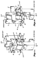
- FIGS. 2A, 2B, 4A, and 4B the basic system is operated without the displacement amplification lever.
- the force transducer 1 is machined from a single piece of material (to minimize hysteresis induced by joint slippage) and is composed of the ground end, the metric end, primary flexures 4, and amplification flexures 2.
- To the force transducer there is attached a mirror bracket 5, and retroreflectors 6 and 7.
- On the mirror bracket there are beam turning mirrors 8, 9, 10, and 11, along with spatial displacement monitoring retroreflectors 12, 13, and 14. It can be seen in FIGS.
- interference fringes are experienced and counted at the fringe counter, allowing establishment of a relationship between load and interference fringes, which are proportional to the relative displacement in the z direction of the two retroreflectors 6 and 7, while being relatively immune to asymmetric displacement anomalies.
- a total relative displacement of ⁇ z between retroreflectors 6 and 7 is experienced under an applied load P.
- retroreflectors 6 and 7 have been replaced with retroreflectors 15 and 16 which are mounted directly on the displacement amplification lever 3.
- the displacement amplification lever 3 is attached to both the ground and metric ends of the force transducer 1 through the displacement amplification flexures 2 which are separated from one another by a distance Lf. If the metric end is deflected downward by a distance ⁇ z, it can be seen that retroreflector 15 is deflected downward and retroreflector 16 is deflected upward.
- the displacement amplification lever is experiencing a rotation of ⁇ degrees in the x-z plane, and a translation of ⁇ z/2 in the -z direction.
- the ratio of Lf/Lr was 10, thus giving an order of magnitude increase in resolution, or the ability to resolve 0,048 kg (0.0013 pound) on a system capable of (300 pounds) full scale. This corresponds to a resolution of 0.0004% of full scale.
- FIGS. 3A and 3B it can be seen that the optical paths A and B are not really changed from the configurations which do not use the displacement amplification lever; conversely, retroreflectors 15 and 16 both experience motion, resulting in the optical path length of beam A getting longer while path B gets shorter.
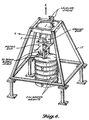
- Retroreflectors 12, 13, and 14 were used throughout all testing phases to monitor and correct for relative spatial orientation changes between the interferometer and the force transducer. Translations along the y axis which resulted in longer or shorter optical paths had no adverse effect on the data as both paths A and B changed by the same amount and in the same direction. However, as the system was loaded, any rotation of the test stand 17, reference FIG. 6, (in this Figure the force transducer is configured for tension load applications) about the z axis (racking), or about the y axis (leaning), would erroneously indicate deflections owing to loads which are not present, because the optical path lengths, A and B, would differentially change.
- retroreflectors 12, 13, and 14 By using retroreflectors 12, 13, and 14 to describe and monitor the x-z plane, there is ability to correct for these anomalies. Additionally, the force transducer and laser beam manipulating array of mirrors and dretroreflectors were designed such that symmetry was maintained, thus also minimizing the effects which could otherwise have been caused by differential temperature growth.
- the prototype force transducer can be used in two different configurations as shown in FIGS. 1 and 2. In each configuration, a force measurement is possible because of the relative movement between the metric and ground ends. This movement occurs through the flexures 4 in the axial direction and the flexures have very little movement in the other directions, even if lateral forces are present. The movement in the prototype was about 0,025 cm ( ⁇ .010") in the axial direction. To measure the very small distances involved, a laser interferometer was used.
- Twin laser beams come in from a distance and reflect off of 45° mirrors 9 and 10.
- the beams then hit another pair of 45° mirrors 8 and 11, (mirrors 8, 9, 10 and 11 are held to the ground end by bracket 5) this sends them to a pair of retroreflectors 6 and 7.
- the light then traces the same path back where it is picked up by an interferometer.
- the interferometer detects the change in the number of wavelengths which fit in the light path.
- a computer may be used to record the change by counting the number of wavelengths which pass. Atmospheric disturbance of the light is compensated for by the twin beams, since the beams lie close together they should experience close to the same changes caused by any atmospheric disturbances.
- the measurement of the relative movement between the ground and metric ends is computed from the difference in the apparent path change in the two beams. If the atmosphere causes any change in the apparent path length, it will affect both beams and the difference between the two will be zero.
- the interferometers we used were capable of measurements with a resolution of 8.10 -7 cm (0.0000003 in.), which theoretically would give ⁇ 33,333 counts of resolution in the 0,025 cm ( ⁇ .010 in.) deflection of our prototype.
- the flexures could be designed for a much larger deflection which would give a corresponding increase in resolution.
- the difference in the configuration in FIG. 1 is the addition of a mechanical amplifier to which the retroreflectors 15 and 16 are mounted.
- the amplifier consists of a lever 3 which is connected to a rectangular shaft 17 by two tapered joints and two bolts.
- the rectangular shaft 17 is also one piece with the flexures 2.
- One flexure is one piece with the ground end while the other is one piece with the metric end.
- the measured deflection at the retroreflectors 15 and 16 is increased by the ratio Lr:Lf over the deflection between the ground and metric ends (see FIG. 5).
- the advantage of using the mechanical amplifier is an increased difference in path lengths of the twin laser beams without an increase in deflection between the ground and metric ends, yielding an increase in resolution, accuracy, and repeatability over the configuration without the mechanical amplifier.
- the only disadvantage known for the mechanical amplifier is an increased sensitivity to dynamic loading. Depending on the loading conditions measured, the accuracy of the interferometer used, and the requirements for the measurement, a mechanical amplifier may or may not be necessary.
- a key feature of the prototype is its one-piece construction. This prevents any slippage across a joint which would introduce error into the measurement. Pieces which do not carry a load other than their own weight are secured with bolts and press fit pins to prevent any relative movement across the joint.
- the lever 3 is secured to the rectangular shaft 17 by two tapered joints (which lock to each other) and two bolts.
- the retroreflectors 15 and 16 are held in their sockets by spring clips (not shown).
- the mirrors 8, 9, 10 and 11 are held in their holes by two set screws each.
- a second key feature of the prototype is the arrangement of the ground and metric ends with the flexures 4.
- This geometry produces a structure which is very stiff in every direction except the z direction. This makes the prototype very insensitive to forces and moments except a force in the z direction.
- the stiffness in the z direction can be controlled by choosing an appropriate geometry and number of flexures. The designer can control the stiffness, maximum deflection under maximum load, and stress level for a given application. By designing to a given stress level, problems which plague strain gage force transducers can be avoided. Stresses can be reduced to levels below those which would cause fatigue, creep, or anelasticity problems. A less expensive or alternate material with special properties could be used by controlling the stress level to suit that material.
- the retroreflectors 12, 13, and 14 mounted on the bracket 5 are used by three laser beams which also go to independent interferometers. Any movement of the retroreflectors is detected by the interferometers and may be stored in computer memory. This information is used to detect any movement in the ground end and also to compensate for any slight disturbance of the mirrors and other optical equipment which routes the laser beams.
- the computer can compensate for these effects by a "rigid body” program.
- the program computes the constants it needs when a mirror is purposely disturbed during set up. The effect of using the "rigid body” program is less sensitivity to movement in the optical and structural support equipment.
- An advantage in using interferometers is their digital output which can be processed by noise-free digital computers.
- An advantage in laser light over strain gages is their unrestricted temperature range limited only by the retroreflector material. Since there is little stress induced to the retroreflector, there is no fatigue or bonding problems
Landscapes
- Physics & Mathematics (AREA)
- General Physics & Mathematics (AREA)
- Length Measuring Devices By Optical Means (AREA)
Claims (5)
- Transducteur de force interférométrique à laser comportant un unique trajet de charge de pièce pour éliminer l'hystérésis à un niveau micro, comprenant :un transducteur de force (1) qui est usiné à partir d'une pièce unique du matière en minimisant sinsi l'hystérésis introduite par le glissement d'articulations et ayant une extrémité de base, une extrémité de mesure, dus éléments fléchissants principaux (4) et facultativement aussi des éléments fléchissants (2) d'amplification ;l'extrémité de base étant reliée à l'extrémité de mesure par chacun des éléments fléchissants principaux (4) et facultativement aussi par chacun des éléments fléchissants (2) d'amplification ;un support (5) de miroirs fixé au transducteur de force (1) ;des premier et second rétroréflecteurs (6, 7 ; 15, 16) ;plusieurs miroirs (8, 9, 10, 11) de renvoi de faisceau fixés au support (5) de miroirs ;
caractérisé parplusieurs rétroréflecteurs (12, 13, 14) de surveillance de débattement spatial fixés audit support (5) de miroirs. - Transducteur de force interférométrique à laser selon la revendication 1, dans lequel le premier rétroréflecteur 7 est monté sur l'extrémité de base et le second rétroréflecteur (6) est monté sur l'extrémité de mesure du transducteur de force (1).
- Transducteur de force interférométrique à laser selon la revendication 1, dans lequel un levier (3) d'amplification de déplacement est fixé aux éléments fléchissants (2) d'amplification et dans lequel le premier rétroréflecteur (16) et le second rétroréflecteur (15) sont fixés au levier (3) d'amplification de déplacement.
- Transducteur de force interférométrique à laser selon la revendication 3, dans lequel l'extrémité de base est reliée à l'extrémité de mesure par des éléments fléchissants principaux (4), au moins un élément fléchissant (2) d'emplification, un arbre rectangulaire (17) et au moins un autre élément fléchissant (2) d'amplification, en série.
- Transducteur de force interférométrique à laser selon la revendication 4, dans lequel le levier (3) d'amplification de débattement est monté sur l'arbre rectangulaire (17).
Applications Claiming Priority (3)
| Application Number | Priority Date | Filing Date | Title |
|---|---|---|---|
| US08/086,795 US5446546A (en) | 1993-07-02 | 1993-07-02 | Laser interferometric single piece force transducer |
| PCT/US1994/007339 WO1995001555A1 (fr) | 1993-07-02 | 1994-06-29 | Transducteur de forces utilisant l'interferometrie laser |
| US86795 | 1998-05-28 |
Publications (2)
| Publication Number | Publication Date |
|---|---|
| EP0706644A1 EP0706644A1 (fr) | 1996-04-17 |
| EP0706644B1 true EP0706644B1 (fr) | 2000-08-09 |
Family
ID=22200976
Family Applications (1)
| Application Number | Title | Priority Date | Filing Date |
|---|---|---|---|
| EP94921420A Expired - Lifetime EP0706644B1 (fr) | 1993-07-02 | 1994-06-29 | Transducteur de forces utilisant l'interferometrie laser |
Country Status (6)
| Country | Link |
|---|---|
| US (1) | US5446546A (fr) |
| EP (1) | EP0706644B1 (fr) |
| AU (1) | AU7215494A (fr) |
| DE (1) | DE69425498T2 (fr) |
| RU (1) | RU2142122C1 (fr) |
| WO (1) | WO1995001555A1 (fr) |
Cited By (1)
| Publication number | Priority date | Publication date | Assignee | Title |
|---|---|---|---|---|
| CN111380477A (zh) * | 2020-02-10 | 2020-07-07 | 湖南科技大学 | 一种多场环境下构件尺寸稳定性在线检测系统及检测方法 |
Families Citing this family (26)
| Publication number | Priority date | Publication date | Assignee | Title |
|---|---|---|---|---|
| US6706358B1 (en) | 1998-04-09 | 2004-03-16 | Seagate Technology Llc | Storage disk comprising depressions and /or raised features |
| US6564626B2 (en) | 1999-11-26 | 2003-05-20 | The Boeing Company | Apparatus and method for measuring forces and moments acting on models tested in aerodynamic wind tunnels |
| US7030551B2 (en) * | 2000-08-10 | 2006-04-18 | Semiconductor Energy Laboratory Co., Ltd. | Area sensor and display apparatus provided with an area sensor |
| US6717678B2 (en) * | 2000-12-08 | 2004-04-06 | Zygo Corporation | Monolithic corrector plate |
| US7101053B2 (en) * | 2004-01-15 | 2006-09-05 | Associated Universities, Inc. | Multidirectional retroreflectors |
| US7209240B1 (en) | 2004-08-05 | 2007-04-24 | The United States Of America As Represented By The Secretary Of The Navy | System and apparatus for measuring displacements in electro-active materials |
| US7236252B1 (en) | 2004-08-05 | 2007-06-26 | The United States Of America As Repersented By The Secretary Of The Navy | System and apparatus for measuring displacements in electro-active materials |
| US8075498B2 (en) | 2005-03-04 | 2011-12-13 | Endosense Sa | Medical apparatus system having optical fiber load sensing capability |
| US8182433B2 (en) * | 2005-03-04 | 2012-05-22 | Endosense Sa | Medical apparatus system having optical fiber load sensing capability |
| US8894589B2 (en) | 2005-08-01 | 2014-11-25 | Endosense Sa | Medical apparatus system having optical fiber load sensing capability |
| WO2007109616A2 (fr) * | 2006-03-17 | 2007-09-27 | William Marsh Rice University | Système et procédé pour mesurer la contrainte et la déformation à l'échelle nanométrique dans des matériaux |
| US8048063B2 (en) * | 2006-06-09 | 2011-11-01 | Endosense Sa | Catheter having tri-axial force sensor |
| US8567265B2 (en) | 2006-06-09 | 2013-10-29 | Endosense, SA | Triaxial fiber optic force sensing catheter |
| US8157789B2 (en) * | 2007-05-24 | 2012-04-17 | Endosense Sa | Touch sensing catheter |
| US8622935B1 (en) | 2007-05-25 | 2014-01-07 | Endosense Sa | Elongated surgical manipulator with body position and distal force sensing |
| US8298227B2 (en) * | 2008-05-14 | 2012-10-30 | Endosense Sa | Temperature compensated strain sensing catheter |
| CN103607961B (zh) | 2011-04-14 | 2016-12-14 | 圣犹达医疗用品卢森堡控股有限公司 | 用于导管的紧凑型力传感器 |
| CN103196598A (zh) * | 2013-04-16 | 2013-07-10 | 北方工业大学 | 一种光电式力传感器 |
| WO2016190921A1 (fr) | 2015-02-05 | 2016-12-01 | Associated Universities, Inc. | Télémètre laser à fibre optique |
| WO2017118949A1 (fr) | 2016-01-07 | 2017-07-13 | St. Jude Medical International Holding S.À R.L. | Dispositif médical doté de fibre à multiples cœurs pour détection optique |
| CN111141744B (zh) * | 2019-12-31 | 2023-01-31 | 广州维思车用部件有限公司 | 一种镜片检测装置 |
| CN111707335B (zh) * | 2020-07-06 | 2024-10-18 | 中国科学院西北生态环境资源研究院 | 一种激光称重装置及其真空低温试验环境下的应用系统 |
| US20230176313A1 (en) * | 2021-12-02 | 2023-06-08 | Plx, Inc. | Self-aligning active retroreflector system and method |
| CN114323273B (zh) * | 2021-12-06 | 2024-06-25 | 中国计量科学研究院 | 一种基于多重反射的光压测量装置及方法 |
| DE202022103358U1 (de) | 2022-06-15 | 2022-06-21 | Pawan Kumar Arora | Ein laserbasierter Kraftaufnehmer |
| DE102024122003B3 (de) * | 2024-08-01 | 2025-12-24 | Neura Robotics GmbH | Vorrichtung zur Messung einer Kraft und/oder eines Drehmoments |
Family Cites Families (15)
| Publication number | Priority date | Publication date | Assignee | Title |
|---|---|---|---|---|
| DE138704C (fr) * | ||||
| DE143956C (fr) * | ||||
| US3092914A (en) * | 1960-09-08 | 1963-06-11 | Sr Harold K Buscher | Gauge amplifier |
| US3438251A (en) * | 1965-07-26 | 1969-04-15 | Lord Corp | Optical transducer |
| FR1487837A (fr) * | 1966-07-26 | 1967-07-07 | Lord Corp | Transducteurs optiques |
| SE354115B (fr) * | 1971-10-13 | 1973-02-26 | Lasergruppen Konsuit Ab | |
| US3790284A (en) * | 1972-05-08 | 1974-02-05 | Hewlett Packard Co | Interferometer system for measuring straightness and roll |
| US3903734A (en) * | 1974-02-11 | 1975-09-09 | Bruce E Douglas | Technique for measuring the complex shear modulus utilizing laser interferometry |
| CA994547A (en) * | 1974-07-22 | 1976-08-10 | National Research Council Of Canada | Optical system for angle measurement by interferometry |
| DD137619A1 (de) * | 1978-07-11 | 1979-09-12 | Gerd Jaeger | Vorrichtung,insbesondere zur digitalen kraftmessung |
| US4261107A (en) * | 1980-03-06 | 1981-04-14 | Caterpillar Tractor Co. | Coordinate locating device |
| US4432239A (en) * | 1981-12-08 | 1984-02-21 | Bykov Anatoly P | Apparatus for measuring deformation |
| FR2584489B1 (fr) * | 1985-07-08 | 1990-06-08 | Bertin & Cie | Dispositif pour controler la geometrie d'une structure mecanique. |
| KR890700814A (ko) * | 1987-01-21 | 1989-04-27 | 한스 빌헬름 해프너, 거드쿠도르퍼 | 광학센서 |
| DE3720248A1 (de) * | 1987-06-19 | 1989-01-05 | Schenck Ag Carl | Verfahren und anordnung zur messung von verformungen an proben oder pruefkoerpern in pruefmaschinen |
-
1993
- 1993-07-02 US US08/086,795 patent/US5446546A/en not_active Expired - Fee Related
-
1994
- 1994-06-29 WO PCT/US1994/007339 patent/WO1995001555A1/fr not_active Ceased
- 1994-06-29 AU AU72154/94A patent/AU7215494A/en not_active Abandoned
- 1994-06-29 DE DE69425498T patent/DE69425498T2/de not_active Expired - Lifetime
- 1994-06-29 RU RU96102025A patent/RU2142122C1/ru active
- 1994-06-29 EP EP94921420A patent/EP0706644B1/fr not_active Expired - Lifetime
Cited By (1)
| Publication number | Priority date | Publication date | Assignee | Title |
|---|---|---|---|---|
| CN111380477A (zh) * | 2020-02-10 | 2020-07-07 | 湖南科技大学 | 一种多场环境下构件尺寸稳定性在线检测系统及检测方法 |
Also Published As
| Publication number | Publication date |
|---|---|
| US5446546A (en) | 1995-08-29 |
| WO1995001555A1 (fr) | 1995-01-12 |
| AU7215494A (en) | 1995-01-24 |
| DE69425498T2 (de) | 2001-01-11 |
| EP0706644A1 (fr) | 1996-04-17 |
| DE69425498D1 (de) | 2000-09-14 |
| RU2142122C1 (ru) | 1999-11-27 |
Similar Documents
| Publication | Publication Date | Title |
|---|---|---|
| EP0706644B1 (fr) | Transducteur de forces utilisant l'interferometrie laser | |
| US7918143B2 (en) | Platform balance | |
| US5490427A (en) | Six axis force sensor employing multiple shear strain gages | |
| US6826960B2 (en) | Triaxial acceleration sensor | |
| AU2006201171B2 (en) | Optical accelerometer, optical inclinometer and seismic sensor system using such accelerometer and inclinometer | |
| US6912902B2 (en) | Bending beam accelerometer with differential capacitive pickoff | |
| US3949603A (en) | Strain gage transducer | |
| US6564626B2 (en) | Apparatus and method for measuring forces and moments acting on models tested in aerodynamic wind tunnels | |
| JPS6361609B2 (fr) | ||
| JPH04500562A (ja) | 位置測定装置 | |
| US7100458B2 (en) | Flexure system for strain-based instruments | |
| US5509211A (en) | Multi-coordinate probe | |
| Burns et al. | Wind tunnel balance design: A NASA Langley perspective | |
| Richman et al. | Preliminary determination of G using the BIPM torsion strip balance | |
| US4138884A (en) | Multi-axis load cell | |
| US4344495A (en) | Equipment for the measurement of minute weight forces | |
| US3438251A (en) | Optical transducer | |
| US5095749A (en) | Proofmass suspension assembly for accelerometers | |
| US3997976A (en) | Sensitive tiltmeter | |
| NL2027778B1 (en) | Fibre-optic sensor for measuring a physical quantity | |
| US7024949B2 (en) | Load transducers employing a sensing device | |
| US4580645A (en) | Constant moment weigh scale with misalignment compensator | |
| US3092424A (en) | Self-compensated flexure pivot | |
| US20060191355A1 (en) | Platform balance | |
| Mana et al. | Non-linear analysis of the elastic behaviour of a translation device for x-ray interferometry |
Legal Events
| Date | Code | Title | Description |
|---|---|---|---|
| PUAI | Public reference made under article 153(3) epc to a published international application that has entered the european phase |
Free format text: ORIGINAL CODE: 0009012 |
|
| 17P | Request for examination filed |
Effective date: 19951010 |
|
| AK | Designated contracting states |
Kind code of ref document: A1 Designated state(s): DE |
|
| 17Q | First examination report despatched |
Effective date: 19970923 |
|
| GRAG | Despatch of communication of intention to grant |
Free format text: ORIGINAL CODE: EPIDOS AGRA |
|
| GRAG | Despatch of communication of intention to grant |
Free format text: ORIGINAL CODE: EPIDOS AGRA |
|
| GRAH | Despatch of communication of intention to grant a patent |
Free format text: ORIGINAL CODE: EPIDOS IGRA |
|
| GRAH | Despatch of communication of intention to grant a patent |
Free format text: ORIGINAL CODE: EPIDOS IGRA |
|
| GRAA | (expected) grant |
Free format text: ORIGINAL CODE: 0009210 |
|
| AK | Designated contracting states |
Kind code of ref document: B1 Designated state(s): DE |
|
| REF | Corresponds to: |
Ref document number: 69425498 Country of ref document: DE Date of ref document: 20000914 |
|
| EN | Fr: translation not filed | ||
| PLBE | No opposition filed within time limit |
Free format text: ORIGINAL CODE: 0009261 |
|
| STAA | Information on the status of an ep patent application or granted ep patent |
Free format text: STATUS: NO OPPOSITION FILED WITHIN TIME LIMIT |
|
| 26N | No opposition filed | ||
| PGFP | Annual fee paid to national office [announced via postgrant information from national office to epo] |
Ref country code: DE Payment date: 20130627 Year of fee payment: 20 |
|
| REG | Reference to a national code |
Ref country code: DE Ref legal event code: R071 Ref document number: 69425498 Country of ref document: DE |
|
| PG25 | Lapsed in a contracting state [announced via postgrant information from national office to epo] |
Ref country code: DE Free format text: LAPSE BECAUSE OF EXPIRATION OF PROTECTION Effective date: 20140701 |